![]() AC CLOUD CONTROLInstallation SheetINWFIDAI001R0XX
AC CLOUD CONTROLInstallation SheetINWFIDAI001R0XX
HMS Industrial Networks S.L.U© 2019 HMS Industrial Networks S.L.U All rights reserved.
This document has been carefully written by HMS Industrial Networks S.L.U and a lot of effort has been made to ensure no errors or mistakes are present in the document. HMS Industrial Networks S.L.U is not responsible for printing or clerical errors.Information in this document is subject to change without notice. No part of this publication may bereproduced, stored in a retrieval system or transmitted in any form or any means electronic or mechanical,including photocopying and recording for any purpose other than the purchaser’s personal use without thewritten permission of HMS Industrial Networks S.L.U.HMS Industrial Networks S.L.UMilà i Fontanals, 708700 IgualadaSpain
IntesisTM is a trademark of HMS Industrial Networks S.L.U Third-party product names, company names, and logos used in this document may be trademarks of their respective companies. Their use in this document is purely for information purposes only.
Safety instructions
![]() WARNING
WARNING
Follow carefully these safety and installation instructions. Improper work may lead to serious harm for your health and may damage seriously the interface and/or the AC indoor unit.
- This interface must be installed by accredited technical personnel (electrician, installer, or authorized technicalpersonnel) and following all the safety instructions.
- This interface must only be installed in a restricted access location.
- Before manipulating the AC indoor unit be sure it is completely disconnected from the Mains power.
- In case of installation of the interface inside the AC indoor unit, fix the interface and communication cables preferably to any appropriate point of the plastic cover of the unit taking care of no blocking free movement of mobile parts and as far as possible from tubes containing liquids and power cables.
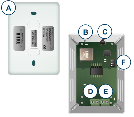
Device information
A. LidB. LED indicatorC. Push buttonD. AC connectorE. External Power Supply ConnectorF. DIP-Switch
Device connection
- Unplug the Air Conditioner (AC) unit from the mains.
- Access to the main Printed Circuit Board.
- Locate the P1 / P2 socket connector.
- Select a location for the device.
- Connect the AC Cloud Control device to the Air Conditioner.
- Close the Air Conditioner unit.
- Plug the AC into the power supply line
 AC Cloud Control device
- Wi-Fi Access Point or Router
- P1 / P2 connector
- Remote Controller (RC)
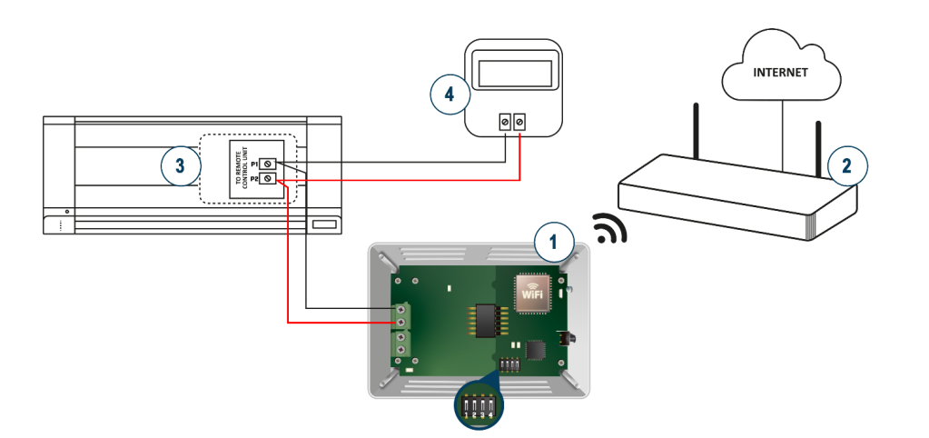 AC Cloud Control device
External powering scheme
Important: If a wired remote controller of the AC manufacturer is connected to the same bus, communication may shut down. In case it happens, use an external power supply connected to the PS connector in our device to overcome this situation.Connect an NEC Class 2 or Limited Power Source (LPS) and SELV-rated power supply to the device, respect the polarity. Apply always a voltage within the range admitted and of enough power (12V DC, min. 100 mA).

Switch configuration
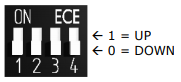
Please, make sure that switches are placed in the right position as per your desired settings.
| Switches1234 | Description |
| 1 X X X | Master—DK BRC Controller not needed in P1 P2 bus. If it exists, it must be configured as Slave |
| 0 XX X | Slave-A DK BRC Controller must be present in P1 P2 bus configured as Master (Default value) |
| X 1 X X | Daikin Remote Controller ambient temperature reading |
| X 0 X X | Daikin Indoor Unit ambient temperature reading (Default value) |
| XXIX | High-Performance Mode (Default value) |
| X X OX | Low Power Mode |
| X XX 1 | Max WIFI power (Default value) |
| X X XO | WIFI power is limited |
Switch 1If your device is set up as Master (SW1-OFF), it will always show the temperature measured by the Daikin Indoor Unit. If your device is set up as Slave (SW1-ON):
- If SW2 is OFF, then AC Cloud Control will show the temperature measured by the Daikin indoor unit.
- If SW2 is ON, then AC Cloud Control will show the temperature measured by the Daikin remote controller.
Switch 3This switch determines the performance of the device. Running in High-Performance Mode means maximum consumption and maximum device performance.
Switch 4This switch determines the Wi-Fi range of the device. The maximum range is set by default. Consider that changing this switch may affect to device Wi-Fi communication, happening a device in a running installation not to reach the current access point or Wi-Fi network to which is connected.
In case no external supply is used: In very specific installations, AC port consumption may be overpassed, leading the device to reboot. If that happened, decrease device consumption by using SW3 and SW4.
NOTE: Remember that you need to power cycle the climate system or the AC Cloud Control device for the changes in the switches to be applied.
© HMS Industrial Networks S.L.U – All rights reserved This information is subject to change without notice
References
[xyz-ips snippet=”download-snippet”]