
Intesis IS-IR-WI-FI-1 AC Cloud Control
Important User Information
DisclaimerThe information in this document is for informational purposes only. Please inform HMS Industrial Networks of any inaccuracies or omissions found in this document.HMS Industrial Networks disclaims any responsibility or liability for any errors that may appear in this document. HMS Industrial Networks reserves the right to modify its products in line with its policy of continuous product development. The information in this document shall therefore not be construed as a commitment on the part of HMS Industrial Networks and is subject to change without notice. HMS Industrial Networks makes no commitment to update or keep current the information in this document.
The data, examples and illustrations found in this document are included for illustrative purposes and are only intended to help improve understanding of the functionality and handling of the product. In view of the wide range of possible applications of the product, and because of the many variables and requirements associated with any particular implementation, HMS Industrial Networks cannot assume responsibility or liability for actual use based on the data, examples or illustrations included in this document nor for any damages incurred during installation of the product. Those responsible for the use of the product must acquire sufficient knowledge in order to ensure that the product is used correctly in their specific application and that the application meets all performance and safety requirements including any applicable laws, regulations, codes and standards. Further, HMS Industrial Networks will under no circumstances assume liability or responsibility for any problems that may arise as a result from the use of undocumented features or functional side effects found outside the documented scope of the product. The effects caused by any direct or indirect use of such aspects of the product are undefined and may include e.g. compatibility issues and stability issues.
Description
Introduction
AC Cloud Control is the perfect IoT solution for professional AC management. It has been developed along with the mayor AC manufacturers and offers the possibility to control almost any domestic, commercial or VRF AC unit in the market from a generic dashboard available for Android, iOS or in any web browser.
The AC Cloud Control system offers many functionalities covering different needs like energy saving and air conditioner maintenance just to name some of them. All these functionalities make the product the best professional solution for offices, stores, schools or any other commercial building.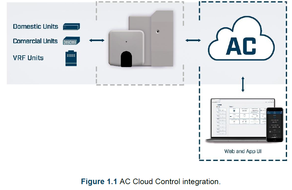
About this document
This document describes how to built-in binary input in the Universal controller. The binary input allows Universal controllers owners to add a standard presence sensor or window contact to it. It offers the possibility to make automatic actions depending on if there is presence or not in the room or if the window is opened or closed.
What is needed
In order to use AC Cloud Control system is needed, at least, the following:
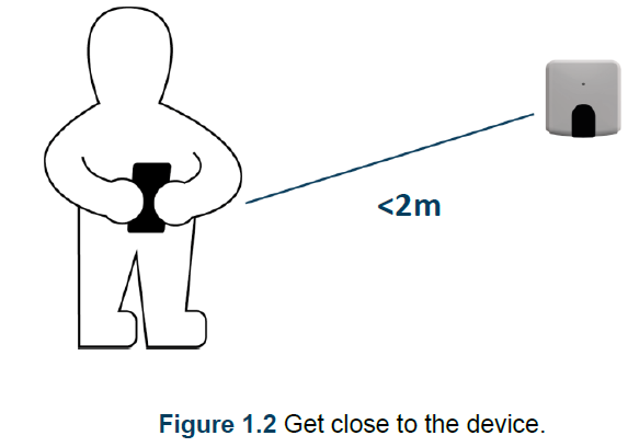
- AC Control device.Before start using the binary input, AC Cloud Control is needed to (if the user hasn’t done yet) an AC Cloud Control Universal device1. In addition, is necessary be close to it (See Figure 1.2)

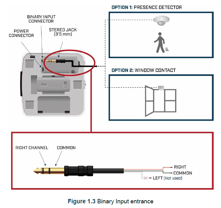
- Make sure to choose the right entrance of the sensor.In order to use the built-in binary input in all the Universal Controllers (See Figure 1.3), the entrance of the sensor selected must use a standard 3,5 mm stereo jack connector (See Figure 1.4)
- Internet access2.The AC Cloud Control Universal devices must be connected to internet using Wi-Fi, so make sure the Wi-Fi signal reaches the device location (See Figure 1.5).
- Device with Internet access:A device with internet access is needed (Desktop/laptop computer).Make sure the desktop/laptop computer supports at least one of the following web browsers (See Figure 1.6).


Installation
Presence sensor Window contact
Once the installation is done properly with the specifications, double check how the sensor is going to be used. The sensor only needs to be equipped with a potential free external contact. No matter if the contact is NO (Normally Open) or NC (Normally Closed) as the user will be able to configure the contact type (NO or NC) of the sensor.
Note: Only one sensor can be connected (presence sensor or a window contact one), both sensors cannot work together at same time.Recommendation: In some presence sensors or window contacts it is possible to setup a delay time to the external contact. As it can be seen in this manual, AC Cloud Control Settings allow the users to setup a timer before starting with the configured actions. Anyway, is recommend to setup a certain delay time in the presence sensor or window contact in order to prevent continuous contact changes in a very short period.Note: Universal controller will only react if the contact of the sensor is opened or closed. In the case of the presence sensor, the installer needs to decide the specific settings of the presence sensor to be applied. AC Cloud Control will be not responsible of the incorrect settings or incorrect installations.
Sleep mode
The sleep mode function modifies the standard behavior of the binary input. Therefore.
Note: sleep mode will be only available when the binary input is activated.
When the sleep mode is active, the binary input will be able to turn the AC unit on when presence is detected for the first time. It will remain in this status even if no presence is detected afterwards. If the unit is turned off manually either from the AC Cloud Control system (App, Web, calendar or scenes) or from the AC unit remote controller, the presence function will not be able to turn it on while sleep mode is active.
Example A: User is sleepingThe sleep mode function is enabled at 20:00, when the user is supposed to be sleeping, through a Calendar action or a Scene. Once enabled, a single trigger of the presence sensor will cause the AC unit to turn on and remain in this status although the presence sensor reports “no presence” afterwards.
Example B: User is cold/hotThe sleep mode function is enabled at 20:00, when the user is supposed to be sleeping, through a Calendar action or a Scene. Maybe the room is already at a proper temperature and even getting too cold or hot. If the user decides to manually turn the AC unit off, it will remain in this status until the user or any calendar action or scene is turning the AC unit on again.
Binary input configuration
Note: The Binary input functionality will only apply if the AC unit is ON. Otherwise, the Presence or Window Contact functionalities will not make any change on the AC unit status.
The configuration of the Binary input must be done through the web interface.
- Go to https://accloud.intesis.com
- Login. (See Figure 3.1).
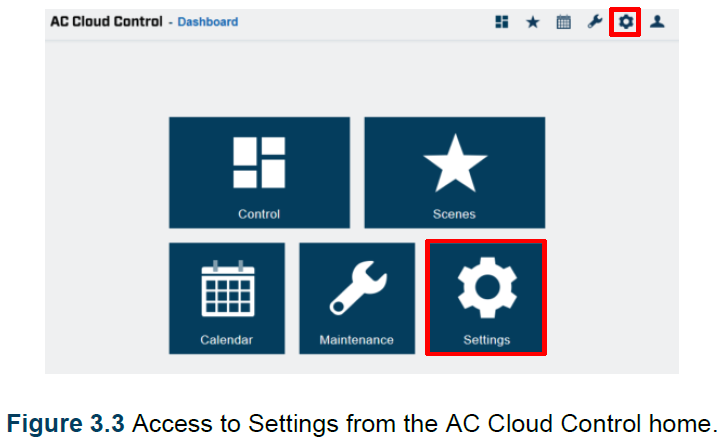
- Go to Settings, either clicking on settings button or on the settings icon of the quick access menu placed in the top in the right side (See Figure 3.2).
- Click on devices and select the Universal AC Cloud Control device from the left menu (See Figure 3.3).
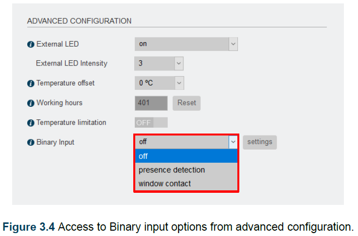
- In advanced configuration the Binary input in the dropdown menu the options “off”, “presence detection” or “window contact” can be selected (See Figure 3.4).
- Off: Binary input is disabled
- Presence detection: Binary input is enabled, and the setup actions can be performed when the room is occupied or not occupied.
- Window contact: Binary input is enabled, and the setup actions can be performed when the window is closed or opened (it could also be a door).


Presence sensor
There are some configurations to be done after select presence detection (See Figure 3.5)
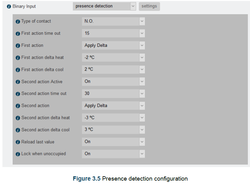
“Type of contact”: Select what type of contact the sensor has: Normally Open (NO) or Normally Closed (NC).“First action time out”: (minutes) When no presence is detected, this is the time the Universal controller will wait to execute First action.“First action”: Select what type of action will be executed as First action between “Apply delta” or “Switch Off” the Unit. Note that if “Switch off” is selected, then a second action is not available. If “Apply delta” is selected, the user can setup different delta temperatures for Heat and Cool. The user could also setup a second action.“First action delta heat”: Setup the delta temperature to be applied when unit is working in Heat mode (Only if First action is “Apply delta”).“First action delta cool”: Setup the delta temperature to be applied when unit is working in Cool mode (Only if First action is “Apply delta”).“Second action active”: Setup and execute a second action. Only available if first action was “Apply delta”.“Second action timeout”: (minutes) After executing the First action, this is the time the IR WIFI controller will wait to execute the Second action.“Second action”: Select what type of action will be executed as second action between “Apply delta” or “Switch Off” the Unit.“Second action delta heat”: Setup the delta temperature to be applied when unit is working in Heat mode (Only if Second action is “Apply delta”).“Second action delta cool”: Setup the delta temperature to be applied when unit is working in cool mode (Only if Second action is “Apply delta”).“Reload last value”: After “Apply delta” action is executed, if presence is detected in the room, the unit will start working as at the beginning. That means in the same way as the unit was working when Presence was detected, in other words the delta temperatures applied will be back.On the other hand, if the last executed action was Switch off, then the unit will remain off if this setting is in “Off” or will recover the last operation commands if this setting is in “On”.“Lock when unoccupied”: This setting overwrites any change made from the Wireless remote controller. Only changes from AC Cloud Control App or Web are allowed.
Window contact
There are some configurations to be done after select Window contact (See Figure 3.6).
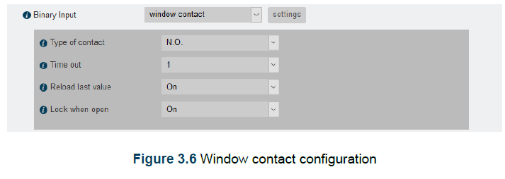
“Type of contact”: Select what type of contact the sensor has. Normally Open (NO) or Normally Closed (NC).“Time out”: (minutes)When the window or door is opened, this is the time the IR WIFI controller will wait to execute the Action “Switch Off the AC”.“Reload last value”: After the window or door is closed again, the AC unit will remain off if this setting is in “Off” or will recover the last operation commands if this setting is in “On”.“Lock when open”: This setting overwrites any change made from the Wireless remote controller. Only changes from AC Cloud Control App or Web are allowed.
Control Panel
Presence sensor
When the function Presence detection is activated, in the control screen it will appear a new widget called “Binary Input”This widget can show 4 different states:
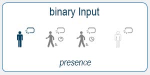
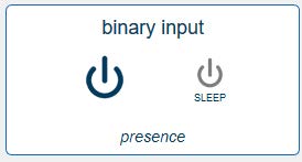
- State 1: Presence (See Figure 4.1)This state indicates to the user that the room is occupied, and any Presence Detection action is in progress.
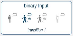
- State 2: Transition 1 (See Figure 4.2)This state indicates that the room is currently unoccupied and the “First action time out” is in progress.Note: If the AC Unit is Off or is turned Off during transition 1, the time out progress will be stopped.
- State 3: Transition 2 (See Figure 4.3).This state indicates that the room is currently unoccupied and:
- First action was executed.
- The “Second action time out” is in progress.Note: If the AC Unit is turned Off during transition 2, the system will go back to Transition 1 state.
- State 4: No presence (See Figure 4.4)This state indicates that the room is currently unoccupied and:
- Second action was executed.
- No more actions will be executed until presence will be detected.
 Note: If the AC Unit is Off or is turned Off during transition 1, the time out progress will be stopped.
 Note: If the AC Unit is turned Off during transition 2, the system will go back to Transition 1 state.
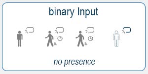
Window contact
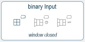
When the function Window contact is activated, in the control screen it will appear a new widget called “Binary Input”This widget can show 3 different states:
- State 1: Window closed (See Figure 4.5)This state indicates that window or door is closed, and any Window Contact action is in progress.
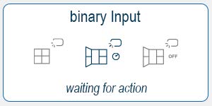
- State 2: Waiting for action (See Figure 4.6)This state indicates that the window or door is currently open and the “Time out” is in progress. Note: If the AC Unit is Off or is turned Off during Waiting for action state, the time out progress will be stopped.
- State 3: Window opened (See Figure 4.7)This state indicates that the window or door is currently open and:
- Unit was Switch OFF.
- No more actions will be executed until window or door is closed.
 Note: If the AC Unit is Off or is turned Off during Waiting for action state, the time out progress will be stopped.
Sleep mode
 report this ad
Sleep mode can only be activated when the user is creating calendar pattern or a scene. Click on the widget for the binary input and later the sleep icon.There are three different positions that the widget shall have:
- Binary input for presence and sleep mode active: When presence and sleep mode are active. The binary input will be only used to turn the AC unit on, if presence is detected and ON status will remain like this at least since the sleep mode is active or any user, calendar or scene turns the AC unit off (See Figure 4.8).
- Binary input for presence active, but sleep mode inactive: When presence is active, but sleep mode is not active. The binary input will work as usual with a presence sensor connected to it (See Figure 4.9). More information about the presence function can be found in Section 3.1 and Section 4.1.
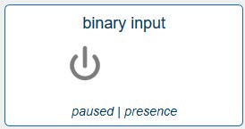
- Binary input for presence and sleep mode inactive: When nor presence or sleep mode are active. In this case, the reported status of the presence sensor will take no effect on the AC unit status or current working mode (See Figure 4.10).

References
[xyz-ips snippet=”download-snippet”]