![]()
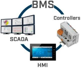
BACnet MS/TP & Modbus RTU interface for HVAC integration
Compatible with IR-enabled AC units, from most AC brands
INTESIS MAPS IN485UNI001I000 CONFIGURATION MANUAL
Issue date: 04/2021 r1.0 ENGLISH


Important Information
Disclaimer
The information in this document is for informational purposes only. Please inform HMS Industrial Networks of any inaccuracies or omissions found in this document. HMS Industrial Networks disclaims any responsibility or liability for any errors that may appear in this document.
HMS Industrial Networks reserves the right to modify its products in line with its policy of continuous product development. The information in this document shall therefore not be construed as a commitment on the part of HMS Industrial Networks and is subject to change without notice. HMS Industrial Networks makes no commitment to update or keep current the information in this document.
The data, examples and illustrations found in this document are included for illustrative purposes and are only intended to help improve understanding of the functionality and handling of the product. In view of the wide range of possible applications of the product, and because of the many variables and requirements associated with any particular implementation, HMS Industrial Networks cannot assume responsibility or liability for actual use based on the data, examples or illustrations included in this document nor for any damages incurred during installation of the product. Those responsible for the use of the product must acquire sufficient knowledge in order to ensure that the product is used correctly in their specific application and that the application meets all performance and safety requirements including any applicable laws, regulations, codes and standards. Further, HMS Industrial Networks will under no circumstances assume liability or responsibility for any problems that may arise as a result from the use of undocumented features or functional side effects found outside the documented scope of the product. The effects caused by any direct or indirect use of such aspects of the product are undefined and may include e.g. compatibility issues and stability issues.
| ORDER CODE | LEGACY ORDER CODE |
| IN485UNI001I000 | – |
1 Presentation
This user manual stands for IN485UNI001I000 configuration in Intesis Maps®. For the specific application (BACnet or Modbus integration as BACnet EDE, Modbus register map, etc.), please, refer to the specific product BACnet or Modbus user manuals available in the product page.
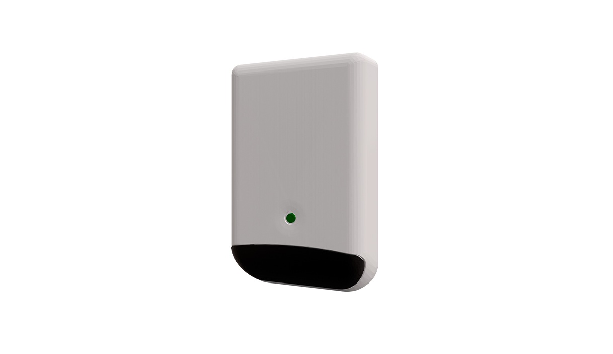
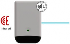
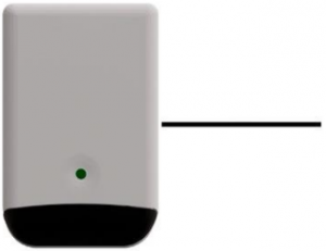
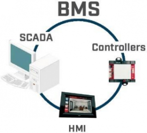
Intesis gateway IN485UNI001I000 provides full integration of infrared-enabled air conditioners into BACnet MS/TP & Modbus RTU networks (over EIA-485).
Compatible with most AC units equipped with an IR receiver.
![]()

![]()

![]()
1.1 Defining BACnet MSTP or Modbus RTU integration
Setting the BMS protocol (BACnet MSTP or Modbus RTU) to integrate the AC unit is done in the main view of the software.
To integrate an AC unit in BACnet MSTP network use the template Intesis IR to BACnet Server gateway and to integrate an AC unit into a Modbus RTU network use Intesis IR to Modbus slave gateway instead as shown in the image:
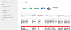
Remember that the product doesn’t communicate in both protocols at the same time (BACnet/Modbus) and is not intended for a quick change of the communication protocol. However, is possible to change between BACnet and Modbus protocols by downloading a configuration done in a different template.
1.2 Necessary or recommended elements for device configuration
Here is the list of the necessary or recommended elements for the device configuration:
- BACnet MS/TP & Modbus RTU interface for HVAC integration Intesis interface (IN485UNI001I000).
- PC with Intesis Maps® installed (Internet connection recommendable).
- Mini USB cable type B for device connection to the PC (not included with the product).
- Native infrared remote controller of the AC indoor unit to integrate (highly recommendable). If there were different infrared remotes in the same project, have one of each model with you by the time you do the devices configuration.
2 Configuration
To configure the device, start Intesis Maps® configuration software in your PC. Intesis Maps® is a free software available in the product page at www.intesis.com.
The settings available in both projects (BACnet/Modbus) is coincident in most of parameters and sections. For those which are not equivalent, the differences will be discussed along this manual in every specific point.
2.1 Connection 
Access to this view to connect to a device which is physically connected to the PC*.
Once the device is connected to the PC, the LED of the Intesis device should blink in orange. This confirm that the device is reachable from Intesis Maps® so once the LED blinks in this color, the device is ready to be connected from the software:

Connect to the device using Connect button. Once the software is connected to the interface, the lower bar will indicate is as shown in the image, and the product LED will turn into intense steady orange:
![]()
Remember that is not necessary to be connected to a device to do its configuration. It is also possible to do its configuration offline and later connect the device for the download. However, it is recommendable to have at least one device by the time you start with the configuration to use the autolearn function.
*To know more about the connection of this device towards the PC or the installation, consult the user manual of the interface available in the product page.
2. 2 Configuration
![]()
This section is divided in three different tabs:
- General. Here is possible to edit the tree and adding/cloning interface configurations and edit the name or add a description.
- Modbus slave / BACnet server. Here are the settings regarding the BACnet MSTP or the Modbus RTU communication.
- IR. Here are the settings of the infrared configuration and different device settings.
Consider that many of these settings can be updated in real time from the BMS protocol (BACnet MSTP/Modbus RTU) by using the dedicated object or register. Available settings via BMS protocol can be consulted in BACnet or Modbus user manual or in the signals tab for this product, in Intesis Maps.
2.2.1 General
This is the main view of the software. From this section is possible to operate over the tree view and over the number of devices in the project.
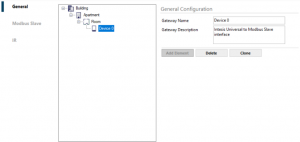
To modify the name of an element of the tree, click on it and edit it on the right side*. It is also possible to add a description of a gateway for the integrator reference.
To add an element (building part or new device), click in the level to add the new part and click in add element:
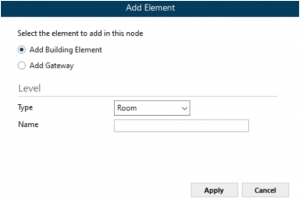
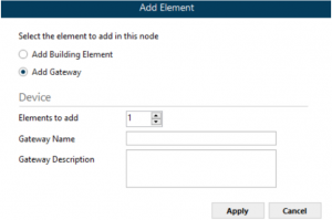
To add a new building part, add a name and click apply.
To add a new gateway(s), add a name a description and set the number of devices to add into your project.
Apart of adding new elements, it is also possible to clone device configuration** or an entire part of the project. Click in the desired element of the tree and press clone to replicate this element and the ones included below it, the elements located in the sublevel(s) of the cloned element.
Click delete to delete a tree element and those located in the sublevels of the deleted item.
The tree supports hold & release function for all the elements except for the highest level (building).
The maximum number of interfaces that can be added to one Intesis Maps project is 128.
*When the Intesis Maps project in use is BACnet, this fields corresponds with the BACnet device name.**Recommended once the tree configuration tabs are completed for the gateway.
2.2.2 BACnet/Modbus
According to the Intesis Maps project selected in the main view, BACnet or Modbus will be in use.
2.2.2.1 BACnet serverThese are the BACnet settings configurable in the interface.
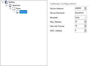
- Device instance. Device BACnet instance of the interface.
- Device password. Device BACnet password of the interface.
- Baudrate. BACnet communication baudrate of the interface. Auto stands for autoconfigure theBACnet baudrate among the supported baudrate (9600, 19200, 38400, 57600, 76800 and 115200).
- Max. Masters. Define the maximum number of BACnet masters of the interface.
- Max info frames. Define the info frames for the BACnet communication of the interface.
- MAC address. It sets the MAC address of the interface.
2.2.2.2 Modbus slaveThese are the Modbus settings configurable in the interface.

- Connection type. It shows the connection type available. The interface supports RS-485 communication only.
- Data type. 8 bits with no polarity with 1 stop bit (8N1) and 8 bits with no polarity with 2 stop bits (8N2) are supported for the interface.
- Baudrate. Set the baudrate for the RS-485 communication (9600, 19200, 38400, 57600, 76800 and 115200)
- Slave number. Set the slave Modbus address of the interface.
2.2.3 IR
The parameters available for the IR configuration are subdivided in different sections:
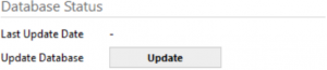
Database status
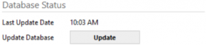
In this part of the settings it is possible to do a DB update of the latest IR codes and FW version available for the interface (IN485UNI001I000).
Gateway configuration


In this section some settings can be defined for the interface:
Automatic IR detection (Autolearn)This function allows to automatically configure the IR to simulate with the interface. To use this function, the native AC infrared remote controller is needed, and the PC requires internet connection.
Clicking in Autolearn will open a new window. Follow carefully the steps indicated in the new window to complete the autolearn process.
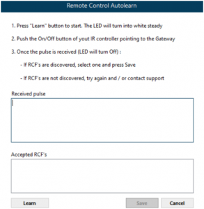
Once the autolearn process is completed, press save to apply the changes. This action will complete the following settings:
- AC Manufacturer
- Remote
Autolearn is the recommended process to configure the IR remote in the Intesis interface. However, it is also possible to do a manual IR configuration by searching the AC manufacturer and remote model from the lists.(only for Modbus template project)
- Modbus temperature registers. Set the temperature registers format in Modbus (x1/x10).
- Temperature scale in Modbus. Set the temperature registers scale in Modbus (ºC/ºF).
- Modbus humidity sensor register. Set the relative humidity registers format in Modbus (x1/x10).
(only for BACnet template project)
- Temperature scale in BACnet. Set the temperature registers scale in BACnet (ºC/ºF).
AC status after startup or device resetThis section stands for the interface behaviour after device startup or reset. The parameters we can find here are the following ones:

After device reset, send to AC the following settings (active/not active): by activating this function, the interface will send the following AC status to the AC unit in case the device booted for any reason.
AC status can imply some or all the following parameters: ON/OFF status, operation mode, setpoint temperature, fan speed, vanes up/down and vanes left/right. Consider that not all these parameters can be set for every AC indoor unit as it depends of the capabilities available in the AC unit. To know which are the capabilities of your AC indoor unit, consult its own technical documentation or check it over the native controller of the AC unit.
Advanced configurationSome advanced parameters can be configured in this section:
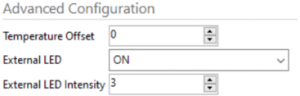
- Temperature offset. Define a temperature offset for the built-in temperature probe of the Intesis interface.
- External LED. Set the LED behaviour of the interface: always off (OFF) always on (ON) or blink only when IR signal is captured (received) or send by the interface.
- External LED intensity. Set the LED intensity of the interface. Default value is 3.
2.3 Signals
![]()
Signals tab stands for the visualization of the signals available in the project. If there is more than one device in the project, their signals will be also visible.
Consider that the BACnet/Modbus signals available are fixed and cannot be disabled from this view in any case. It is not even possible to edit the register number (for Modbus) nor object instances (for BACnet) in the different signals. This product carries the same Modbus map/BACnet EDE than all the Intesis 1 to 1 wired interfaces.
It is possible to check the table of signals to find duplicated device address in the table. When device works as a Modbus interface, slave Modbus addresses will be indicated. When working as a BACnet interface, device instance and/or MAC duplicated addresses are indicated for this function.
It is also possible to export this table by using Export button.
All the signals show the maximum possible values that the signal can accept, and they can be different from the real capacities of the AC indoor unit to integrate. To know which are the capabilities of your AC indoor unit, consult its own technical documentation or check it over the native controller of the AC unit. If that happened, the device accepts all the values and will saturate over the top/low values for your certain AC indoor unit. Remember that working as a Modbus interface, the available values for fan speed and vanes always starts by position 1 until the maximum position allowed for every AC unit.
On the other hand, signals are grouped in three different groups to easily find them in this view:
AC control signalsThese are the common signals to use to integrate your AC unit and get some values from the interface. These signals have the background in white.
AC startup signalsThis group of signals are used to configure the functionality of device startup behaviour. They have the background colour in blue.
Device objectsThis group of signals compounds the own device signals for the integrator reference and configuration. They have the background colour in orange.
BACnet objects EDE or Modbus register signals available can be checked over Intesis Maps software and also over the BACnet/Modbus user manual of the interface.
2.4 Commissioning
The next step is the commissioning of the project. To complete this step, all the Intesis IN485UNI001I000 of the project should be available to program them in case there were more than one interface in the project.
For instance, considering the following tree in our project:
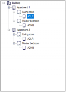
We will find the following devices in our Commissioning tab:
![]()
As we can see, we will have an additional line for every device in our project.
Once the configuration of all the interfaces is completed, the download (programming) process is as it follows:
1. Connect to an interface from the Connection view if no interface is connected at this stage.
![]()
2. Once connected to an interface, come back to commissioning, select the interface to program in your project and press SEND. If the project has not being save until this moment, the software will suggest doing it.
![]() 3. Once the programming was downloaded in the device, its serial number will be assigned to this device configuration in the project and Maps will disconnect from the interface after completing the download.
3. Once the programming was downloaded in the device, its serial number will be assigned to this device configuration in the project and Maps will disconnect from the interface after completing the download.
![]()
4. Repeat steps 1 to 3 with all the remaining devices in the project. Remember to physically connect to a new device before downloading the next configuration.
2.5 Diagnostic
![]()
In this view is possible to perform a diagnostic of the installation by using different signals viewers for the different protocols (IR, BACnet MSTP and Modbus RTU) and simulate values received from one side to another for testing reasons.
In addition, there is a console to communicate against the interface.
ToolBox
If it were necessary, logs can be extracted for a later analysis and troubleshooting. You can find them in the toolbox section. Click in LOG button and save the file where the logs will be stored.

INFO? and a RESET buttons send these commands to the interface via console. Please note that hardware test is not available for this interface:
- INFO command responds with some interface information.
- RESET command will force a device booting. It is necessary to disconnect and reconnect to the interface from the CONNECTION window after using this command.
3 FW update
New firmware updates are checked before sending the configuration to a connected interface. At that moment, Intesis Maps will check if an upper version for the FW is available for the connected device and, in that case, it will send the FW update and the parameters configured for the device at the same time.
So, by doing the steps 2.1 to 2.4 over the desired device, the new FW will be downloaded in the product. After completing the process, you can check the new version over Connection or Diagnostic tabs.
Consider that any settings change done to an installed interface from the BMS protocol will be lost after the FW update. However, it means that Intesis Maps project is not updated with the real device configuration, so it is the best moment to update the Intesis Maps project to keep it up to date. To update its configuration, check the value for the signals in the BMS protocol and translate its configuration to Maps project.
! Consider that updating the FW to an interface that is already configured and located in the installation, the original Intesis Maps project must be used to do the FW update to download the same configuration to the device. Otherwise the configuration in Maps may be different to the current one and affect to device communication after locating the device back to the installation.
! Make sure the PC has internet connection before trying to download the latest FW for this interface. You can check if a new FW is available by using the Update database button.
![]()
© HMS Industrial Networks S.L.U. – All rights reservedThis information is subject to change without notice
References
Intesis | Gateway solutions for Building Automation
Intesis | Gateway solutions for Building Automation
Intesis | Gateway solutions for Building Automation
[xyz-ips snippet=”download-snippet”]