Intesis MD-AC-MBS Misubishi Electric AC Units to Modbus Interface Installation Guide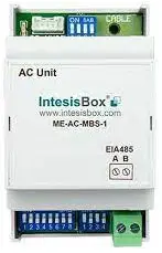
Safety instructions
WARNING
Follow carefully this safety and installation instructions. Not proper work may lead to a serious damage for your health and may harm seriously the interface and/or the AC indoor unit.
- This interface must be installed by accredited technical personnel (electrician, installer or qualified technical personnel) and they must follow all the safety instructions.
- This interface must be installed in an acces restricted location
- Before manipulating the AC indoor unit, make sure it is completely disconnected from Mains Power.
- In case of wall mounting of the interface next to the AC indoor unit, attach the interface safely following the instructions of the diagram below.
- In case of installation of the interface inside the AC indoor unit, attach the interface and communication cables preferably to any proper point of the plastic cover of each unit and take care to not block free movement of mobile parts. Locate them as far as possible from pipes containing liquids and power cables.
Installation instructions
- Disconnect the air conditioning from the Mains Power.
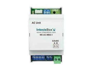
- Attach the interface next to the AC indoor unit (wall mounting) following the instructions of the diagram below or install it inside the AC indoor unit (respect the safety instructions given above).
- Connect the connection cable included with the interface between the interface and the AC indoor unit following the intructions of the diagram below.
- Connect the EIA-485 bus to the connector EIA485 of the interface.
- Close the AC indoor unit and reconnect it to Mains Power.
- Follow the instructions on the User’s Manual to configure and commission the interface.
- Follow the instructions of the next page to configure the interface through on-board DIP-switches.
IMPORTANT:
Extending or shortening the connection cable included with the interface may cause the interface not working properly. Keep the connection cable as far away as possible from electrical wires and ground wire. Do not bundle them together.
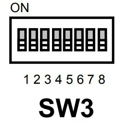
Configuration through DIP switches
IMPORTANT: It is required to reboot or power cycle the interface every time the DIP switch configuration changes.
- Number of Fan Speeds and Vanes configuration.

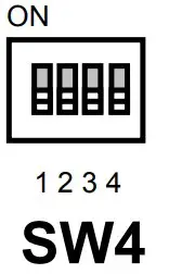
- Configuration of Modbus Slave number and baud rate.
- Configuration of baud rate, temperature magnitude (x1/x10), temperature units (Cº/Fº) and termination resistor for EIA-485.
| SW1-P1…2-4 | Descripción Description |
ON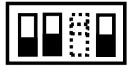 |
AC indoor Unit has 4 fan speeds and AUTO (Default value) |
ON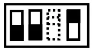 |
AC indoor Unit has 4 fan speeds |
ON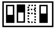 |
AC indoor Unit has 3 fan speeds and AUTO (Default value) |
ON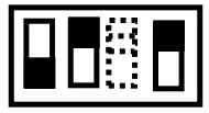 |
AC indoor Unit has 3 fan speeds |
ON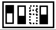 |
Not defined |
ON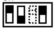 |
AC Indoor Unit has 2 fan speeds |
ON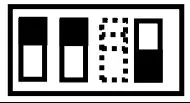 |
Not defined |
ON |
Not defined |
| SW3-P7..8 | SW4-P3 | Description |
ON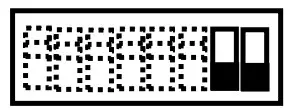 |
ON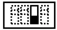 ON ON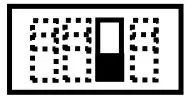 |
2400bps
4800bps |
ON |
||
ON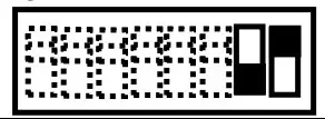 |
ON |
9600bps default value) |
ON |
ON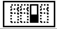 |
19200bps |
ON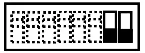 |
ON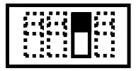 |
38400bps |
ON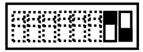 |
ON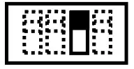 |
57600bps |
ON |
ON |
76800bps |
ON |
ON |
115200bps |
| SW4-P1..2-4 | Description |
ON ON ON |
Temperature values in Modbus register are represented in decidegrees (x10)
Temperature values in Modbus register are represented in degrees (x1) (Default value). |
ON ON ON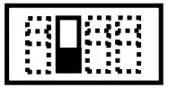 |
Temperature values in Modbus register are represented in Fahrenheit degrees
Temperature values in Modbus register are represented in Celsius degrees (Default value) |
ON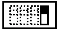 |
Internal termination resistor of 120Ω connected to EIA-485 bus |
ON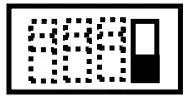 |
EIA-485 bus without termination resistor (Default value). |
| SW1-P3 | Description |
ON |
AC Indoor Unit has auto vanes (Default value) |
ON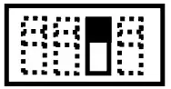 |
AC indoor Unit without auto lamas |

![]() This marking on the product, accessories, packaging or literature (manual) indicates that the product contains electronic parts and they must be properly disposed of by following the instructions at https://intesis.com/weee-regulation
This marking on the product, accessories, packaging or literature (manual) indicates that the product contains electronic parts and they must be properly disposed of by following the instructions at https://intesis.com/weee-regulation
References
[xyz-ips snippet=”download-snippet”]