![]()
INKNXMBM1000100Modbus RTU Master to KNX gatewayOrder Code: INKNXMBM1000100
Installation Sheet rev.1.0HMS Industrial Networks S.L.U ©
SAFETY INSTRUCTIONS
![]() WARNINGFollow carefully this safety and installation instructions. Improper work may lead to serious harmful for your health and also may damage seriously the Intesis gateway and/or any other equipment connected to it.
WARNINGFollow carefully this safety and installation instructions. Improper work may lead to serious harmful for your health and also may damage seriously the Intesis gateway and/or any other equipment connected to it.
The Intesis gateway must be installed by accredited electrician or similar technical personnel, following all the safety instructions given here and in accordance always with the country legislation for installation of electric equipment.
The Intesis gateway cannot be installed outdoors or exposed to direct solar radiation, water, high relative humidity or dust.The Intesis gateway must only be installed in a restricted access location.In case of wall mount, fix firmly the Intesis device on a not vibrating surface following the instructions next.Disconnect always power of any wires before manipulating and connecting them to the Intesis gateway.Respect always the expected polarity of power and communication cables when connecting them to the Intesis deviceSupply always a correct voltage to power the Intesis, see details of voltage range admitted by the device in the technical characteristics below.
CAUTION: The device is to be connected only to networks without routing to the outside plant, all communication ports are considered for indoor only and can be connected SELV circuits only.
This device was designed for installation in an enclosure. To avoid electrostatic discharge to the unit in environments with static levels above 4 kV, precautions should be taken when the device is mounted outside an enclosure. When working in an enclosure (ex. making adjustments, setting switches etc.) typical anti-static precautions should be observed before touching the unit.
Safety instructions in other languages can be found at:
CONFIGURATION
Use the ETS to configure the gateway.Follow the instructions on the user’s manual for configuring and commissioning the interface. See below how to obtain the user’s manual and ETS database.https://www.intesis.com/products/protocol-translator/knxgateways/modbus-rtu-master-to-knx
Owner’s RecordThe serial number is located at the rear of the gateway. Record this information in the space provided below. Refer to it whenever you contact upon your gateway dealer or support team regarding this product.Serial No.______________________________________
INSTALLATION
Follow instructions next to properly install the gateway.Mount the Intesis device on the wall or inside a close electrical junction box (respect the safety instructions given in this document).Disconnect the KNX power supply from the KNX bus.Connect the communication cables to the Intesis device, see details on CONNECTIONS below. Reconnect the KNX power supply to the KNX bus. Connect EIA485 device(s) to its power supply.NOTE: The device cannot be installed in air-handling space.
CONNECTIONS
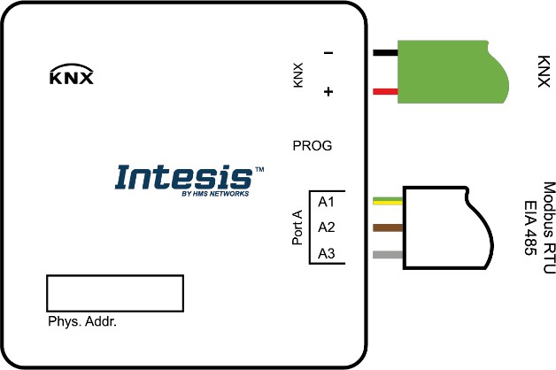 KNX PortConnect the KNX TP1 bus to connectors + and – of gateway’s KNX port. Respect the polarity and use a KNX standard cable.
Port A / Modbus RTUConnect the EIA485 bus to connectors A2 (A-), A3 (B+) and A1 (SNGD) of gateway’s Port A. Remember the characteristics of the standard EIA485 bus: maximum distance of 1200 meters, maximum 32 devices connected to the bus, bus polarization and in each end of the bus it must be a termination resistor of 120 Ω
IMPORTANT:If the INKNXMBM1000100 gateway is not placed at one end of the Modbus channel, the terminal resistor should be deactivated. Remove Jumper 1 to deactivate the 120 Ω terminal resistor.The bus should be polarized only in one location on the line. The INKNXMBM1000100 incorporates 2 jumpers to introduce polarization to the line. It is recommended to keep polarization in the master only. If other device is polarized, remove jumpers 2 and 3 to deactivate polarization in the gateway.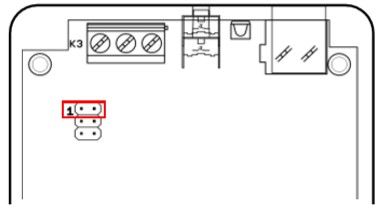
ELECTRICAL & MECHANICAL FEATURES
- Enclosure
- Plastic, type ABS (UL 94 V-0)
- Net dimensions (dxwxh): 71x71x27 mm
- Color: White. RAL 9010
- Mounting
- Wall.
- Power
- Supplied through KNX bus. See on KNX Port.
- KNX Port
- 1 x KNX TP-1 Plug-in screw terminal block (2 poles)
- 2500VDC isolation from other ports
- KNX power consumption: 20mA
- Voltage rating: 29VDC
- Port A
- 1 x Serial EIA485 Plug-in screw terminal block (3 poles)
- A, B, SGND (Reference ground or shield)
- 1500VDC isolation from other ports
- Push Button
- Sets device in programing mode in KNX network
- Operation Temperature
- 0°C to +60°C
- Operational Humidity
- 5 to 95%, no condensation
- Configuration Jumpers
- 3 x Jumpers for serial EIA485 configuration:
- Jumper 1:
- Connected: 120 Ω termination active.
- Disconnected: 120 Ω termination inactive.
- Jumper 2 & 3:
- Connected: Polarization active.
- Disconnected: Polarization inactive.
- LED Indicators
- 3 x Onboard LED indicators
- 2 x Port A TX/RX
- 1 x KNX Prog Mode
![]() This marking on the product, accessories, packaging or literature (manual) indicates that the product contains electronic parts and they must be properly disposed of by following the instructions at https://intesis.com/weee-regulationRev.1.0 © HMS Industrial Networks S.L.U – All rights reserved This information is subject to change without notice URL https://www.intesis.com
This marking on the product, accessories, packaging or literature (manual) indicates that the product contains electronic parts and they must be properly disposed of by following the instructions at https://intesis.com/weee-regulationRev.1.0 © HMS Industrial Networks S.L.U – All rights reserved This information is subject to change without notice URL https://www.intesis.com
![]()
References
[xyz-ips snippet=”download-snippet”]