
![]() Quick Start GuideCEM70™ Center-balanced GoTo Equatorial MountModels: CEM70 (#C70A series) & CEM70G (#C70AG series)
Quick Start GuideCEM70™ Center-balanced GoTo Equatorial MountModels: CEM70 (#C70A series) & CEM70G (#C70AG series)
PACKAGE CONTENTS¹
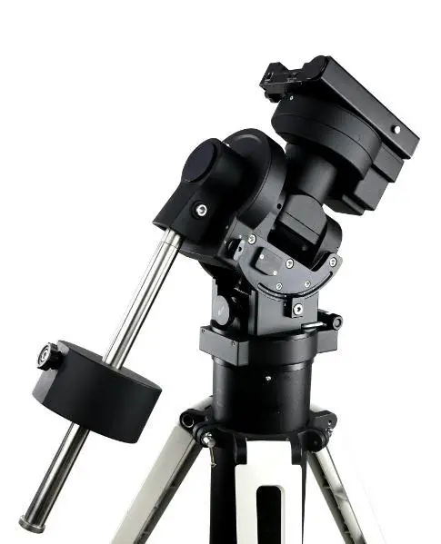
- Mount head – with iPolar™ electronic Polar Scope, C70AG has an onboard iGuider™ guiding scope
- Hand Controller (HC) – Go2Nova® 8407+
- Counterweight – 21 lbs (9.5 kg)
- Stainless steel counterweight shaft
- Built-in GPS module
- Hand controller coiled cables
- RS232-RJ9 serial cable
- USB cable
- AC adapter – 100-240V (DC output 12V/5A)
- Hard case
- Quick Start Guide (this document)
ONLINE RESOURCES (at www.iOptron.com, under Support)
- User’s Manual
- Hand controller and mount firmware upgrades (check online for the latest version)
- ASCOM and Commander for computer control
- Discount coupon code for TheSky™ Imaging Edition
¹The design, contents, and packaging may change from time to time without notice.STOP!!! Carefully read this Guide BEFORE setting up and using the equipment!Worm/gear damages due to improper uses are not covered by the warranty.WARNING: Never disengage Gear Switches without holding the mount firmly! Fail to do so may result in personal injuries and/or equipment damages.
Remove mount head from package:
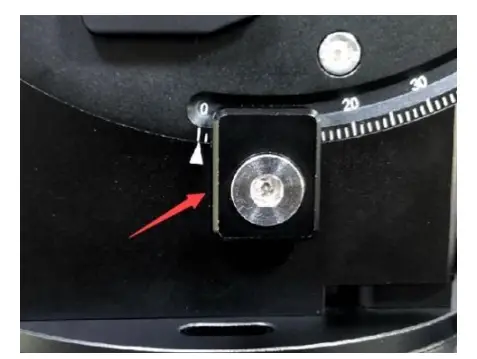
The RA axle is locked by an Allen wrench. Make sure it is inserted all the way in. Check the R.A. Gear Switch and turn it to unlocking position before removing it from the box.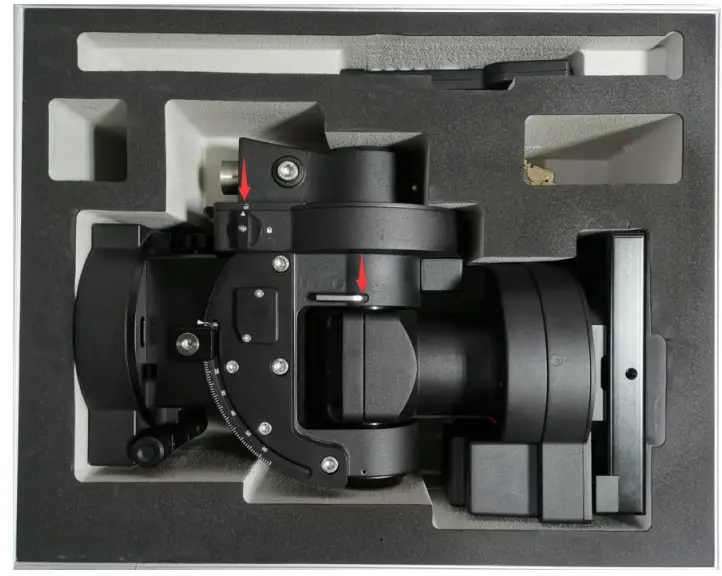
Attach the mount:
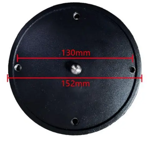
The mount has a 152mm base, which can be mounted onto an iOptron tri-pier, LiteRoc tripod, or your own tripod/pier with two M8 threaded mounting holes separated 130mm in diameter
Hold mount head while removing the Allen wrench from the RA yoke. Turn the RA gear switch to the locking position to prevent RA free swing.Two mounting screws are installed on the base.Rotate the mount to align the screws to the tripod mounting holes. Insert the wrench into the holes on the base where azimuth locking screws are located.
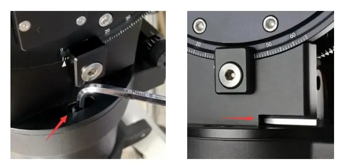
Store the wrench inside the base. The wrench size is 6mm.Level the mount by adjusting the tripod legs. Use the build-in Bubble Level Indicator or an external level for this purpose.
Adjust latitude:
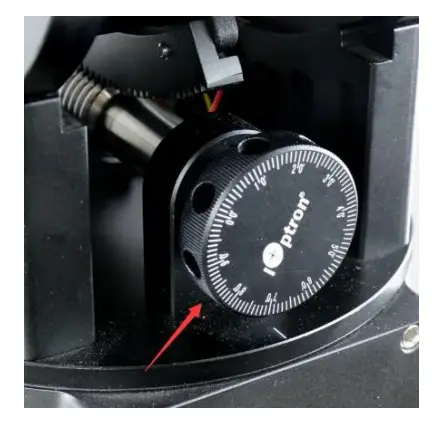
Without any payload, loosen the Latitude Locking Clamps about a quarter (1/4) turn with the Allen wrench.
Turn the Latitude Adjustment Knob until the arrow points to your current latitude on the Latitude Scale.There are fine scales on the Knob, as shown in the photo. Tighten the Latitude Locking Clamps when done.
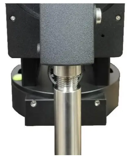
Install counterweight (CW) shaft:
The CW shaft system is a two-part configuration. It comes with the preinstalled top part of the shaft. Just simply thread the CW shaft onto it.[TIP: If your latitude is lower than 10°, please refer to the full online manual to adjust the counterweight shaft position to avoid CW bumping into tripod leg.]
Install counterweight(s):
Before putting on CW, make sure the mount is at its zero position, i.e., CW shaft points to the ground. Disengage the R.A. Gear Switch to set the R.A. axis free before loading the CW. Remove the CW Safety Cap at the end of the CW Shaft. Glide the CW over the shaft with the larger hole opening facing down. Place the Safety Cap back onto the shaft. Move the CW to the bottom of the shaft and tighten the CW locking Screw.
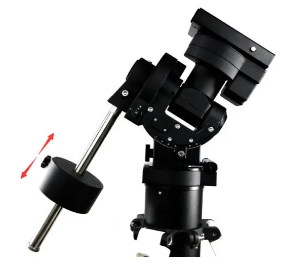
You may need more CW for heavier payloads, or a smaller CW for lighter scopes.
Install telescope:
CEM70 is equipped with a Vixen/Losmandy-D dual saddle. It can receive either a Vixen or a Losmandy-D plate. Release the dovetail saddle locking knobs and slide the telescope dovetail plate into the saddle. Tighten the saddle locking knobs.
Balancing the payload:
After attaching the scope and accessories, the mount head assembly must be balanced in both DEC and RA axes to ensure minimum stresses on the mount driving mechanism.CAUTION: The telescope may swing freely when the R.A. or DEC Gear Switch is disengaged. Always hold on to the mount and/or telescope assembly before releasing the ear Switches to prevent it from swinging, which can cause personal injuries and/or equipment damages.Set the mount at Zero Position. Disengage both RA and DEC gear switches and move the mount to a horizontal position to check balance. Return to Zero Position for balance adjustment. Balance the DEC axis by moving the scope with accessories back and forth in the mount saddle or within the scope mounting rings. Balance the assembly in the R.A. axis by moving CW along its shaft. Repeat the process until both DEC and RA axes are balanced.¹
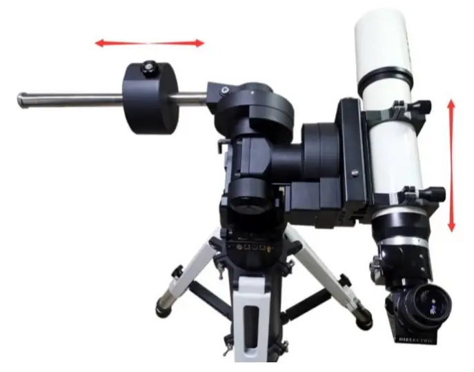
CAUTION: The balancing process MUST be done with Gear Switch at the total disengaged position!Otherwise, it might damage the worm system.Return the mount to Zero Position after balancing and engaging gear switches.
Connecting cables:
Plug in a 12V DC power supply to the DC12V power socket (size 5.5mm/2.5mm).Connect the Go2Nova® 8407 Hand Controller to the HBX port on the mount base panel.
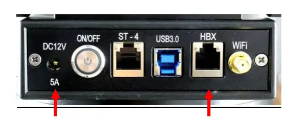
For a CEM70G mount, connect the USB3.0 port on the mount base (shown in the photo here) to a computer for computer control, iPolar, iGuider, and 3X USB port hub connection.
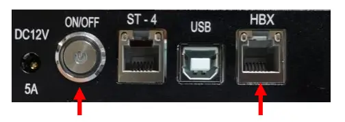
For a CEM70 mount, Connect the USB2.0 port on the mount base to a computer for a computer controller and 3X USB2.0 port hub connection. CEM70 does not have a built-in WIFI.Refer to the full User’s Manual on how to use the cable management system.
Polar alignment:
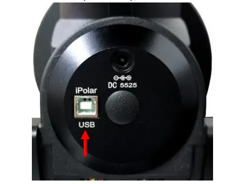
CEM70 & CEM70G are equipped with an iPolar™ electronic polar scope. To perform polar alignment, please refer to CEM70 User’s Manual, or iPolar Operation Manual from iOptron’s website, or follow steps briefly outlined below:
- Download and install iPolar Software (first-time use);
- Connect a USB cable between the iPolar port on the mount (CEM70);
 or USB3.0 port (CEM70G) and a computer USB port;
 - Run iPolar Software and start polar alignment by following on-screen instructions.
 or USB3.0 port (CEM70G) and a computer USB port;
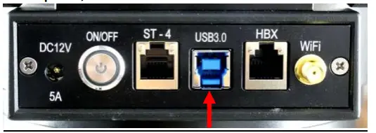
For the mount without a polar scope, please refer to the full manual for Bright Star Alignment, or use software to assist alignment.For the mount with an optional AccuAlign™ optical polar scope, please refer to the full manual for Quick Polar Alignment.
Manual operation:
The mount can now be used to observe astronomical objects with the HC. Use arrow keys (►, ◄, ▼, and ▲) to point the telescope to desired objects. Use the number keys to change the slewing speed. Press the STOP/0 button to start or stop tracking.
Set controller:
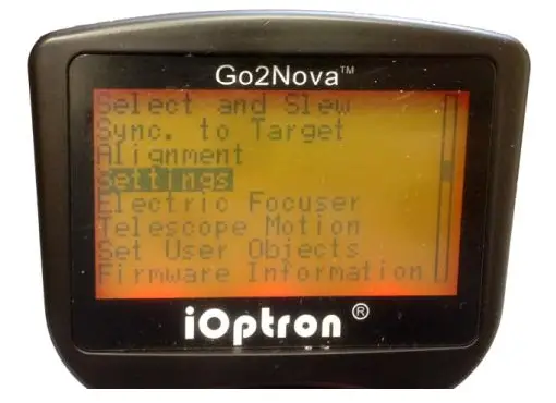
Press the MENU button; then Settings => Set Time and Site.
Before GPS picks up signals (before displaying GPS OK), check for Daylight Saving Time using the arrow key to toggle between Y and N. Enter the time zone offset to the UTC; for example:
- Boston is “UTC -300 minutes”
- Los Angeles is “UTC -480 minutes”
- Rome is “UTC +060 minutes”
- Sydney is “UTC +600 minutes”
Waiting for the mount to pick up the GPS (you’ll hear a beep). If the GPS is “OK’d” during setup, just power cycle the mount. Double-check the HC display and it should show the correct local time.[TIPS: All time zones in N. America are “UTC -XXX minutes”. Latitude and longitude coordinates can be obtained from GPS-equipped devices (navigator, phone), or from the internet and entered manually, in case GPS cannot receive enough satellites signals (unplug the GPS module) or GPS malfunctions. “W/E” = western/eastern hemisphere; “N/S” = northern/southern hemisphere. Use arrow and number keys to enter location and time information.]
Set Zero Position:
The Set Zero Position command registers the current position as zero position. So before registering, the mount should be physically set at Zero Position either manually or slewed by a hand controller. The Zero Position is defined as the telescope being on top of the mount head and pointing to the North Pole, with CW shaft pointing to the ground. To register, press MENU => Zero Position => Set Zero Position. Press ENTER to confirm. One can also use MENU => Zero Position => Search Zero Position to set the Zero Position.
One Star Alignment:
Perform One Star Align to correct the Zero Position discrepancy and improve GOTO accuracy. Refer to the User’s Manual for more details about improving GOTO accuracy.
Go to an object:
The mount is now ready for GOTO and tracking targets. Press MENU, select and ENTER Select and Slew. Select a category (e.g., Solar System), then select an object of interest (e.g., Moon). Press ENTER and the telescope will slew to the object and automatically start tracking.
Sync to target:
If the object is not in the center of the eyepiece, use this function to center and synchronize the object to improve local GOTO accuracy. Press MENU and select and ENTER Sync to Target. Follow the on-screen instruction to perform the sync.[TIP: After slewing to an object, a list of nearby bright object(s) can be displayed by pressing the? button.]
Computer connection and auto-guiding:
Please refer to the CEM70 product page for mount computer control.
Put the mount back into the package/carrying case:
It is recommended to return the mount to Zero Position at the end of the observing session. Lay the mount into the carrying case. Disengage the gear system for transportation and insert the Allen wrench into the RA yoke to lock the RA axis.Please contact [email protected] for technical support.
IOPTRON TWO YEAR TELESCOPE, MOUNT, AND CONTROLLER WARRANTY
A. iOptron warrants your telescope, mount, or controller to be free from defects in materials and workmanship for two years. iOptron will repair or replace such product or part which, upon inspection by iOptron, is found to be defective in materials or workmanship. As a condition to the obligation of iOptron to repair or replace such product, the product must be returned to iOptron together with proof-of-purchase satisfactory to iOptron.B. The Proper Return Merchant Authorization Number must be obtained from iOptron in advance of return. Contact iOptron at 1.781.569.0200 or [email protected] to receive the RMA number to be displayed on the outside of your shipping container. All returns must be accompanied by a written statement stating the name, address, and daytime telephone number of the owner, together with a brief description of any claimed defects. Parts or products for which replacement is made shall become the property of iOptron.The customer shall be responsible for all costs, such as transportation, insurance, and fees, both to and from the factory of iOptron, and shall be required to prepay such costs.iOptron shall use reasonable efforts to repair or replace any telescope, mount, or controller covered by this warranty within thirty days of receipt. In the event repair or replacement shall require more than thirty days, iOptron shall notify the customer accordingly. iOptron reserves the right to replace any product which has been discontinued from its product line with a new product of comparable value and function.This warranty shall be void and of no force or effect in the event, a covered product has been modified in design or function or subjected to abuse, misuse, mishandling, or unauthorized repair. Further, product malfunction or deterioration due to normal wear is not covered by this warranty.IOPTRON DISCLAIMS ANY WARRANTIES, EXPRESS OR IMPLIED, WHETHER OF MERCHANTABILITY OR FITNESS FOR A PARTICULAR USE, EXCEPT AS EXPRESSLY SET FORTH HERE. THE SOLE OBLIGATION OF IOPTRON UNDER THIS LIMITED WARRANTY SHALL BE TO REPAIR OR REPLACE THE COVERED PRODUCT, IN ACCORDANCE WITH THE TERMS SET FORTH HERE. IOPTRON EXPRESSLY DISCLAIMS ANY LOST PROFITS, GENERAL, SPECIAL, INDIRECT, OR CONSEQUENTIAL DAMAGES WHICH MAY RESULT FROM BREACH OF ANY WARRANTY, OR ARISING OUT OF THE USE OR INABILITY TO USE ANY IOPTRON PRODUCT. ANY WARRANTIES WHICH ARE IMPLIED AND WHICH CANNOT BE DISCLAIMED SHALL BE LIMITED IN DURATION TO A TERM OF TWO YEARS FROM THE DATE OF ORIGINAL RETAIL PURCHASE.Some states do not allow the exclusion or limitation of incidental or consequential damages or limitation on how long an implied warranty lasts, so the above limitations and exclusions may not apply to you.This warranty gives you specific legal rights, and you may also have other rights which vary from state to state.iOptron reserves the right to modify or discontinue, without prior notice to you, any model or style telescope.If warranty problems arise, or if you need assistance in using your telescope, mount, or controller contact:
![]() iOptron CorporationCustomer Service Department6F Gill StreetWoburn, MA 01801www.ioptron.com[email protected]Tel. (781)569-0200Fax. (781)935-2860Monday-Friday 9 AM-5 PM EST
iOptron CorporationCustomer Service Department6F Gill StreetWoburn, MA 01801www.ioptron.com[email protected]Tel. (781)569-0200Fax. (781)935-2860Monday-Friday 9 AM-5 PM EST
NOTE: This warranty is valid to the U.S.A. and Canadian customers who have purchased this product from an authorized iOptron dealer in the U.S.A. or Canada or directly from iOptron. Warranty outside the U.S.A. and Canada is valid only to customers who purchased from an iOptron Distributor or Authorized iOptron Dealer in the specific country. Please contact them for any warranty.
References
[xyz-ips snippet=”download-snippet”]