![]()
Quick Start Guide
SkyGuide™ Pro Camera MountModel: 3550 & 3550A
PACKAGE CONTENTS1
- SkyGuider™ Pro camera mount with built-in Li-ion rechargeable battery
- AccuAlign™ dark field illuminated polar scope (#3550) or iPolar (#3550A)
- Alt-azi base
- DEC mounting bracket with DEC camera mounting block
- Vixen-style dovetail saddle for telescope mounting
- Counterweight – 3 lbs (1.35 kg)
- Counterweight shaft
- Micro USB charging cable
- Padded carry bag
ONLINE RESOURCES
- Full Instruction Manual with optional 8408 hand controller
- iPolar (#3339) software and Operation Manual (https://www.ioptron.com/product-p/3339.htm)
- Optional accessories, such as ball head, tripod, hand controller, and camera electrical trigger cables
- Firmware upgrades (check online for the latest version)
- Reviews and feedbacks from other customers
1 Packaging and color may change from time to time without notice. Camera and tripod not included.
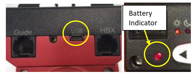
- Charge the battery: The SkyGuider™ Pro is shipped with battery partially charged. It is suggested to fully charge the battery before each session. Insert the micro USB plug into the USB port on the mount, and connect the other end of the USB cable into a USB port of a computer, a smartphone charger or a portable battery pack (not included). The input power should be 5V, 1A. It usually takes 5 hours to charge the internal Li-Poly battery to reach 80% of full power. When the battery is fully charged, the battery status indicator may flash rapidly (about 5Hz). You may charge the mount with the power switch either on or off. (However, when the power switch is turned off, the battery status indicator does not function). When the indicator stays steady on, the battery power should be sufficient for your session. When the indicator blinks slowly (about 0.5Hz), it indicates the power is low and recharging is necessary.
 Please don’t charge the battery or use USB power when temperature is at or below 0°C (32°F), otherwise, the rechargeable battery might be permanently damaged.
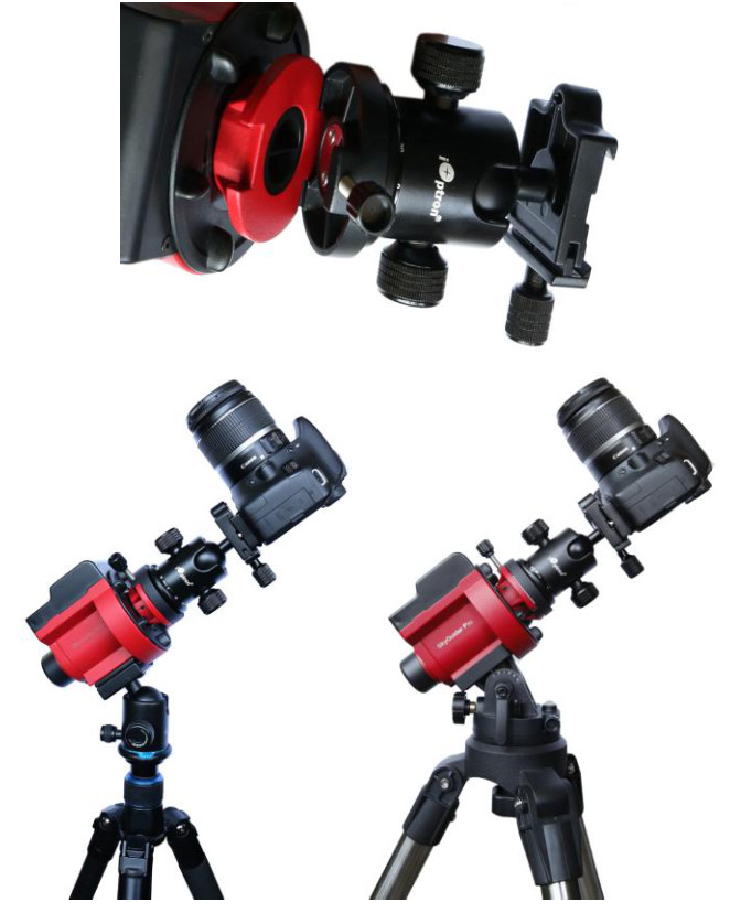
 - Attach the SkyGuider™ Pro mount onto a tripod:The SkyGuider™ Pro mount can be mounted onto a stable tripod with or without the alt-azi base, as shown below. When the alt-azi base is not used, a ball head (such as #3305A, not included) is suggested for an easy adjustment.To use the alt-azi base, just simply slide the mount head base into the alt-azi base dovetail saddle. You can slide the mount head in from either direction depending on your latitude position and payload. The latitude adjustment range can be from -30° to 65°. If possible, choose the one with the center of gravity of the system as close to the center of the base as possible.
- Install a ball head and mount a camera: A DSLR camera can be mounted to the SkyGuider™ Pro mount in many ways. Here are two most practical methods.For a light payload (less than 1.5kg or 3.3lbs, including lens), a DSLR can be attached directly to the SkyGuider™ Pro mount through a ball head. Loosen the Camera Mounting Block locking screw to remove the Camera Mounting Block from the SkyGuider™ Pro mount. Screw the ball head (not included) to the mounting block securely.Reattach the mounting block to the SkyGuider™ Pro mount and tighten the locking screws. Finally, attach the quick release plate of the ball head to the bottom of the DSLR camera, secure it and attach the camera to the ball head.
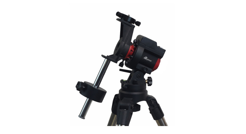
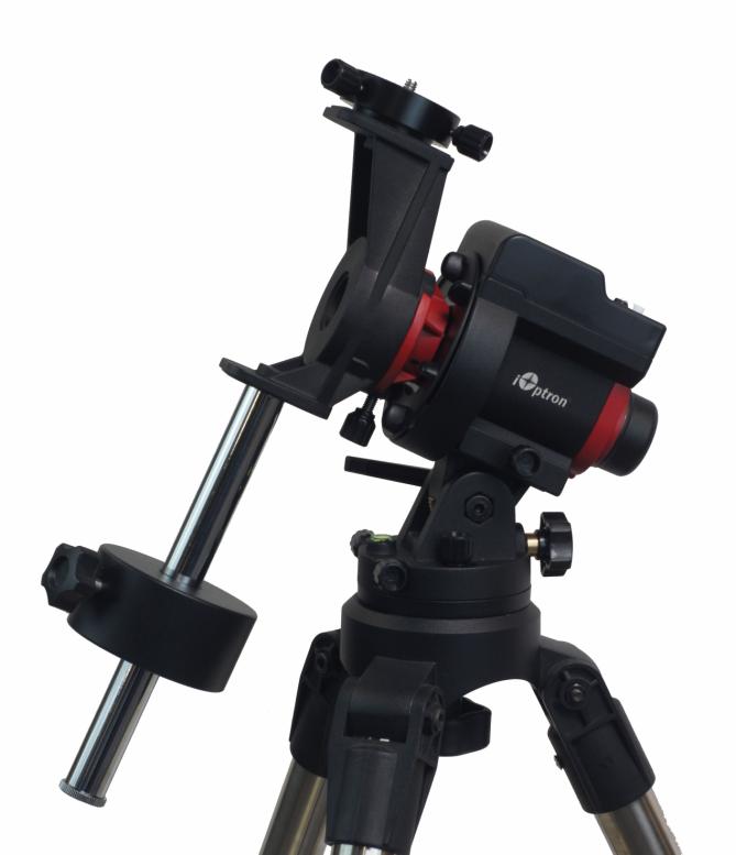
For a heavy DSLR, especially with a long lens (more than 1.5kg or 3.3lbs, including lens), a DEC Mounting Bracket and a counterweight (CW) and CW shaft are needed for better balance and performance.To install the DEC Bracket, remove the Camera Mounting Block from the mount. Remove the polar scope cap. Install the DEC Bracket and tighten the locking screw to secure it. Place the polar scope cap on DEC bracket.Install the CW shaft and load the CW.Loosen two camera mounting block locking screws to remove the DEC Camera Mounting Block from the DEC Base on the DEC Mounting Bracket. Attach the DEC Camera Mounting Block to the bottom of the DSLR camera and secure it by turning the block. Reattach the DEC Camera Mounting Block to the DEC Base and tighten the two locking screws.Release the RA Clutch Disk while hold the camera. Slowly move the camera/CW to horizontal position and balance the load in RA direction by moving the CW position. More than one CW may be used. Return the mount to upward position and lock the RA Clutch Disk again.
- Set the SkyGuider™ Pro mount: Assume you are in northern hemisphere, face the SkyGuider™ Pro mount to the true north, with the assistance of a compass. Please note that true north is not necessarily aligned to the magnetic north from your compass. Release the Latitude Lock half a turn by simply rotating the locking lever counterclockwise. Set the latitude scale at your current latitude by turning the Latitude Adjustment Knob and retighten the latitude lock. The latitude lock handle can be rotated to any suitable position by pulling and turning. Loosen the two Azimuth Locking Knobs, adjust the Azimuth Adjusting Knobs to align the polar axis to the north, and then tighten the Azimuth Locking Knobs. More details on polar alignment are in next step.When power on, the SkyGuider™ Pro mount will be in tracking mode at a rate that shown on the Mount Status Indicator.If your goal is only to take the wide-field image of the sky and stars, set the tracking speed to 1X (celestial tracking speed). With a good polar alignment, this will keep the stars rounded in your image. If you would like to take an image of both the starry sky and the night landscape at the same time, you need to set the tracking speed at 1/2X. This will let you take clear images of both the sky and the land objects at a proper exposure. Solar speed is for tracking the Sun and lunar speed for the moon.Keep pressing the center round button • to change the tracking speed from Solar=>Lunar=>1/2X =>1X.You may fast slew the RA axis by pressing and holding ◄ or ► button while the mount is at tracking mode.The letter “S” indicates if the mount is set to northern or southern hemisphere. If the LED under “S” is on, it indicates the mount is set to southern hemisphere. To change this setting, press and hold the center round button • until the LED under letter “S” starts to blink. Press the • button to toggle between the “S (LED on)” and “N (LED off)”.
- Polar Alignment: To achieve accurate tracking, precise polar alignment is crucial. SkyGuider™ Pro mount offers a quick polar alignment.Easy alignment through polar scopeAim through the polar scope to the Polaris (or Sigma Octantis) while adjusting the azimuth and altitude angles until putting the Polaris at the crosshairs of the polar scope dial. Lock all the knobs when done. The misalignment to North Pole is about 40 min (or about 1 degree in southern hemisphere with Sigma Octantis).If you are using the mount without DEC Bracket, you need to remove the Camera Mounting Block and the camera to perform the polar alignment. If you are using the mount with DEC Bracket, you can do polar alignment with the payload on it.Quick Polar AlignmentYou can use iOptron’s AccuAlign™ dark-field illuminated polar scope for easy and accurate polar alignment. This is achieved by making the polar axis of the mount parallel to the Earth’s axis of rotation.As indicated below, the Polar Scope Dial is divided into 12 hours along the angular direction with 10 min ticks, with a large tick every one hour. Anyone large tick on top can be assigned as 12 o’clock. There are 2 groups, 6 concentric circles marked from 36’ to 44’ and 60’ to 70’, respectively. The 36’ to 44’ concentric circles are for polar alignment in the northern hemisphere using Polaris. While the 60’ to 70’ circles are for polar alignment in the southern hemisphere using Sigma Octantis.Press the power switch on the mount to turn on the mount. Look through the polar scope eyepiece. If you can not see red polar scope dial or a large tick mark is not on top, release RA Clutch Disk slightly. Rotate the RA axis until you see the red LED illumination and/or adjust one of the large tick mark to the top. Lock the RA axis again. Adjust the eyepiece to bring the reticle dial in focus.To maximize the benefits of the iOptron polar scope for polar alignment, you need to know where the Polaris is in the northern (Sigma Octantis in southern) hemisphere. You may find this information via an iPhone/iPad app (Search iOptron Polar Scope in Apple iTune store). As shown in a screenshot of an iPhone, on August 10, 2016, 17:50:18 in Boston, USA (Lat N42°30’28” and Long W71°08’49”), the Polaris Position is 00hr 18.4m and Radius is 40.2min (the green cross on the chart).Adjust the mount in latitude (using Latitude Adjustment Knob) and azimuth (Azimuth Adjusting Knobs) directions to place Polaris in the same position on the Polar Scope Dial as indicated on your iPhone/iPad screen. In this case, the Polaris will be located at a radius of 40.2’ and an angle of 00 hour 18.4 minute.If you feel the polar scope LED is not bright enough, or too bright, you can adjust it. Press and hold the center round • button until the LED under the letter “S” start to blink. Release • button. Press and hold button again until the LED beneath the “ ” is on. Now you can press ◄ or ► button to adjust the polar scope illumination intensity.When done light intensity adjustment, double-check the LED under letter “S” to make sure the correct hemisphere is selected.Polar Alignment with iPolar (#3550A)If you have a SkyGuider Pro with iPolar, please go to iPolar product page to download iPolar software and instruction manual for polar alignment: https://www.ioptron.com/product-p/3339.htm. A PC or Mac computer is needed at the moment.
- Advanced Applications: The SkyGuider™ Pro mount is a versatile mount that can be used in many ways. Some advanced applications/functions are:• Telescope operation (with included Vixen dovetail saddle)• Autoguide via built-in ST-4 compatible GUIDE port.• Dual camera mounting
 Please don’t charge the battery or use USB power when temperature is at or below 0°C (32°F), otherwise, the rechargeable battery might be permanently damaged.
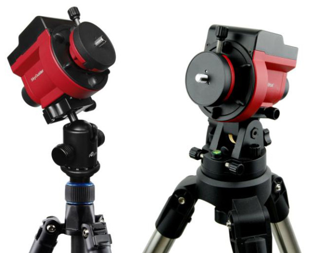 To use the alt-azi base, just simply slide the mount head base into the alt-azi base dovetail saddle. You can slide the mount head in from either direction depending on your latitude position and payload. The latitude adjustment range can be from -30° to 65°. If possible, choose the one with the center of gravity of the system as close to the center of the base as possible.
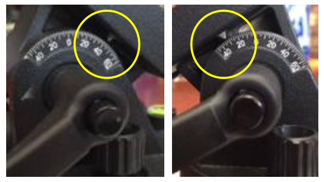
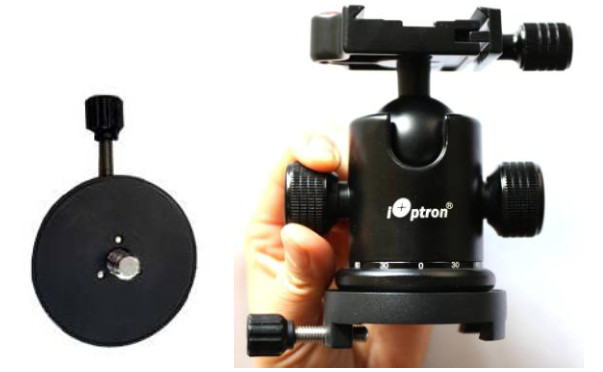 Reattach the mounting block to the SkyGuider™ Pro mount and tighten the locking screws. Finally, attach the quick release plate of the ball head to the bottom of the DSLR camera, secure it and attach the camera to the ball head.
 For a heavy DSLR, especially with a long lens (more than 1.5kg or 3.3lbs, including lens), a DEC Mounting Bracket and a counterweight (CW) and CW shaft are needed for better balance and performance.To install the DEC Bracket, remove the Camera Mounting Block from the mount. Remove the polar scope cap. Install the DEC Bracket and tighten the locking screw to secure it. Place the polar scope cap on DEC bracket.Install the CW shaft and load the CW.Loosen two camera mounting block locking screws to remove the DEC Camera Mounting Block from the DEC Base on the DEC Mounting Bracket. Attach the DEC Camera Mounting Block to the bottom of the DSLR camera and secure it by turning the block. Reattach the DEC Camera Mounting Block to the DEC Base and tighten the two locking screws.Release the RA Clutch Disk while hold the camera. Slowly move the camera/CW to horizontal position and balance the load in RA direction by moving the CW position. More than one CW may be used. Return the mount to upward position and lock the RA Clutch Disk again.
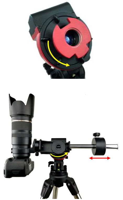
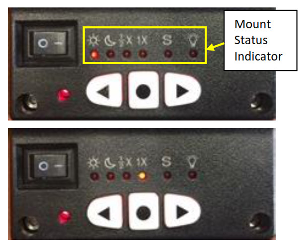 If your goal is only to take the wide-field image of the sky and stars, set the tracking speed to 1X (celestial tracking speed). With a good polar alignment, this will keep the stars rounded in your image. If you would like to take an image of both the starry sky and the night landscape at the same time, you need to set the tracking speed at 1/2X. This will let you take clear images of both the sky and the land objects at a proper exposure. Solar speed is for tracking the Sun and lunar speed for the moon.Keep pressing the center round button • to change the tracking speed from Solar=>Lunar=>1/2X =>1X.You may fast slew the RA axis by pressing and holding ◄ or ► button while the mount is at tracking mode.The letter “S” indicates if the mount is set to northern or southern hemisphere. If the LED under “S” is on, it indicates the mount is set to southern hemisphere. To change this setting, press and hold the center round button • until the LED under letter “S” starts to blink. Press the • button to toggle between the “S (LED on)” and “N (LED off)”.
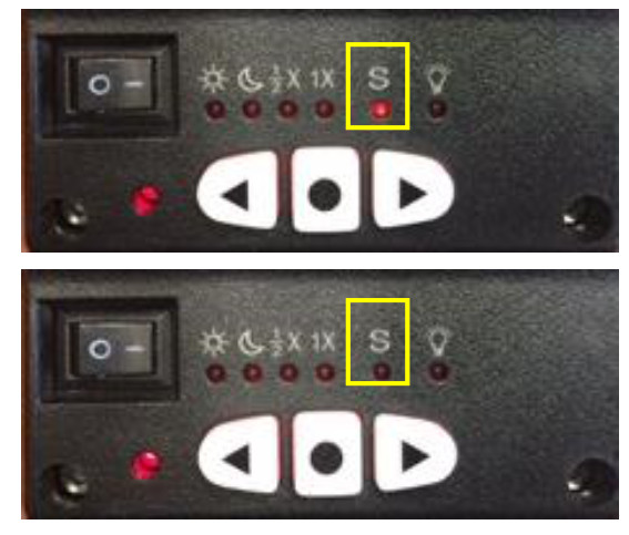
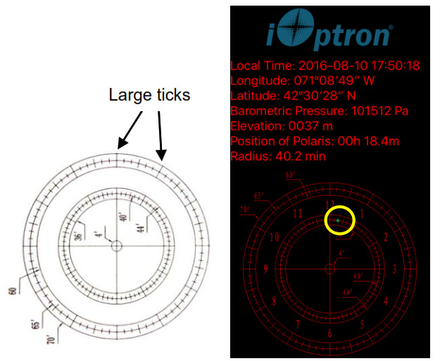 Press the power switch on the mount to turn on the mount. Look through the polar scope eyepiece. If you can not see red polar scope dial or a large tick mark is not on top, release RA Clutch Disk slightly. Rotate the RA axis until you see the red LED illumination and/or adjust one of the large tick mark to the top. Lock the RA axis again. Adjust the eyepiece to bring the reticle dial in focus.To maximize the benefits of the iOptron polar scope for polar alignment, you need to know where the Polaris is in the northern (Sigma Octantis in southern) hemisphere. You may find this information via an iPhone/iPad app (Search iOptron Polar Scope in Apple iTune store). As shown in a screenshot of an iPhone, on August 10, 2016, 17:50:18 in Boston, USA (Lat N42°30’28” and Long W71°08’49”), the Polaris Position is 00hr 18.4m and Radius is 40.2min (the green cross on the chart).Adjust the mount in latitude (using Latitude Adjustment Knob) and azimuth (Azimuth Adjusting Knobs) directions to place Polaris in the same position on the Polar Scope Dial as indicated on your iPhone/iPad screen. In this case, the Polaris will be located at a radius of 40.2’ and an angle of 00 hour 18.4 minute.If you feel the polar scope LED is not bright enough, or too bright, you can adjust it. Press and hold the center round • button until the LED under the letter “S” start to blink. Release • button. Press and hold button again until the LED beneath the “ ” is on. Now you can press ◄ or ► button to adjust the polar scope illumination intensity.
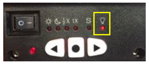 When done light intensity adjustment, double-check the LED under letter “S” to make sure the correct hemisphere is selected.Polar Alignment with iPolar (#3550A)If you have a SkyGuider Pro with iPolar, please go to iPolar product page to download iPolar software and instruction manual for polar alignment:
 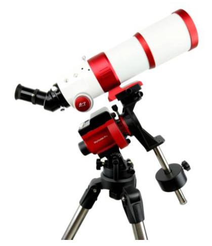 • Autoguide via built-in ST-4 compatible GUIDE port.• Dual camera mounting
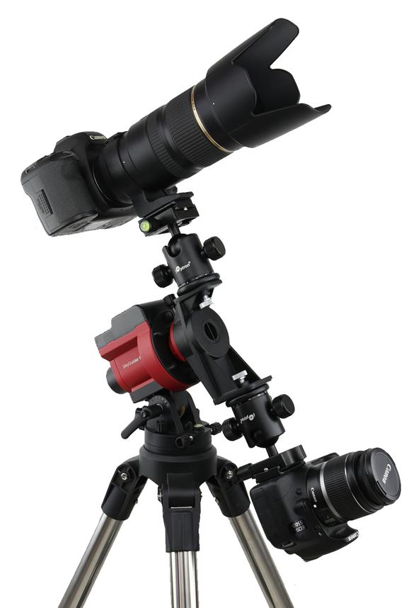
Visit www.iOptron.com for a full instruction manual and accessories. Contact [email protected] for technical supports.
WARRANTY
IOPTRON ONE YEAR TELESCOPE, MOUNT, AND CONTROLLER WARRANTYA. iOptron warrants your telescope, mount, or controller to be free from defects in materials and workmanship for one year. iOptron will repair or replace such product or part which, upon inspection by iOptron, is found to be defective in materials or workmanship. As a condition to the obligation of iOptron to repair or replace such product, the product must be returned to iOptron together with proof-of-purchase satisfactory to iOptron.
B. The Proper Return Merchant Authorization Number must be obtained from iOptron in advance of return. Contact iOptron at [email protected] or 1.781.569.0200 to receive the RMA number to be displayed on the outside of your shipping container. All returns must be accompanied by a written statement stating the name, address, and daytime telephone number of the owner, together with a brief description of any claimed defects. Parts or products for which replacement is made shall become the property of iOptron.
The customer shall be responsible for all costs of transportation and insurance, both to and from the factory of iOptron, and shall be required to prepay such costs.
iOptron shall use reasonable efforts to repair or replace any telescope, mount, or controller covered by this warranty within thirty days of receipt. In the event repair or replacement shall require more than thirty days, iOptron shall notify the customer accordingly. iOptron reserves the right to replace any product which has been discontinued from its product line with a new product of comparable value and function.
This warranty shall be void and of no force of effect in the event a covered product has been modified in design or function or subjected to abuse, misuse, mishandling or unauthorized repair. Further, product malfunction or deterioration due to normal wear is not covered by this warranty.
IOPTRON DISCLAIMS ANY WARRANTIES, EXPRESS OR IMPLIED, WHETHER OF MERCHANTABILITY OF FITNESS FOR A PARTICULAR USE, EXCEPT AS EXPRESSLY SET FORTH HERE. THE SOLE OBLIGATION OF IOPTRON UNDER THIS LIMITED WARRANTY SHALL BE TO REPAIR OR REPLACE THE COVERED PRODUCT, IN ACCORDANCE WITH THE TERMS SET FORTH HERE. IOPTRON EXPRESSLY DISCLAIMS ANY LOST PROFITS, GENERAL, SPECIAL, INDIRECT, OR CONSEQUENTIAL DAMAGES WHICH MAY RESULT FROM BREACH OF ANY WARRANTY, OR ARISING OUT OF THE USE OR INABILITY TO USE ANY IOPTRON PRODUCT. ANY WARRANTIES WHICH ARE IMPLIED AND WHICH CANNOT BE DISCLAIMED SHALL BE LIMITED IN DURATION TO A TERM OF ONE YEAR FROM THE DATE OF ORIGINAL RETAIL PURCHASE.
Some states do not allow the exclusion or limitation of incidental or consequential damages or limitation on how long an implied warranty lasts, so the above limitations and exclusions may not apply to you.
This warranty gives you specific legal rights, and you may also have other rights which vary from state to state.
iOptron reserves the right to modify or discontinue, without prior notice to you, any model or style product.
If warranty problems arise, or if you need assistance in using your telescope, mount, or controller contact:
iOptron CorporationCustomer Service Department6F Gill StreetWoburn, MA 01801www.ioptron.com[email protected]Tel. (781)569-0200Fax. (781)935-2860Monday-Friday 9AM-5PM EST
NOTE: This warranty is valid to U.S.A. and Canadian customers who have purchased this product from an authorized iOptron dealer in the U.S.A. or Canada or directly from iOptron. Warranty outside the U.S.A. and Canada is valid only to customers who purchased from an iOptron Distributor or Authorized iOptron Dealer in the specific country. Please contact them for any warranty.
iOptron Corp. | 6E Gill Street | Woburn, MA 01801 USA | (781) 569-0200 | Toll Free (866) 399-4587 | www.iOptron.com
References
[xyz-ips snippet=”download-snippet”]