![]()
Quick Start Guide
GEM28TM German Equatorial GoTo MountModels: GEM28 (#G28 Series) and GEM28EC (#G28ECA Series)
PACKAGE CONTENTS¹
- Telescope mount with AccuAlign™ dark field illuminated Polar Scope or iPolar™ electronics polar scope
- Hand controller (HC) Go2Nova® 8409
- Tripod with accessory tray 1.5-inch (optional LiteRoc™)
- Counterweight 10.4 lbs X1 (4.7 kg)
- Counterweight shaft
- Counterweight shaft extension
- Controller cables X2
- USB 2.0 cable
- Built-in WiFi
- Mini USB cable (for iPolar) or polar scope LED and cable (for AccuAlign polar scope)
- AC adapter 100-240V
- Optional/external GPS Module (#8438)
- Optional hard case (standard for EC version)
- Optional external iGuider for autoguiding (#3360)
ONLINE RESOURCES (www.iOptron.com)
- User’s Manual
- Tips for set up and using the products
- Hand controller and mount firmware upgrades (check online for the latest version)1 Packaging may change from time to time without notice.
STOP!!! Carefully read this Guide BEFORE setting up and using the equipment! Worm system damage due to user operation error will not be covered by warranty.
WARNING: Never disengage Gear Switches without holding the mount firmly! Personal injury and/or equipment damage may happen.
- Remove mount head from package: The RA axle is locked by an Allen wrench (blue circle). Make sure it is inserted all the way in. Check the R.A. and DEC Gear Switches and make sure they are at the unlock position before removing it from the box.

- Set up tripod: The mount has a 102mm base. Thread the Alignment Peg onto the tripod head, on top of a tripod leg or between two legs depending on the latitude. Insert the Accessory Tray through the center rod and secure the setup by tightening Locking Knob from underneath.
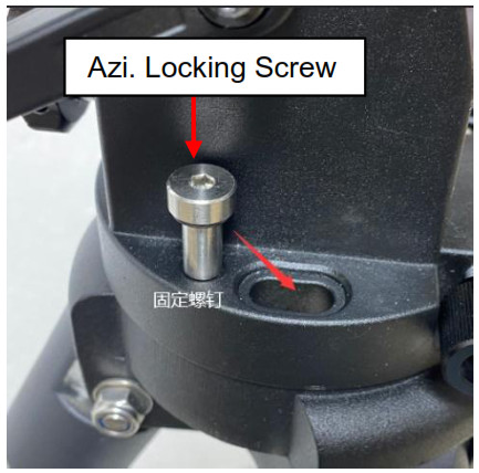
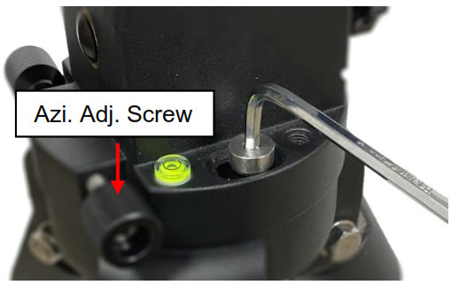
- Attach mount head: Before put the mount onto the tripod, make sure the RA gear switch is at lock position to prevent mount head free swing by accident! Retract the 2x Azimuth (Azi) Adjustment Screws from both sides to leave ample space for the alignment peg to be fitted in between the 2x Azi Adjustment Screws. Remove the 2x Azi Locking Screws from the mount base. Secure the mount head by tightening the Azi Locking Screws into the M6 holes on the tripod. After tighten the Azi Locking Screws, store the Allen wrench at the bottom of the mount altitude support.Rotate the mount head to normal position.Level the mount by adjusting the tripod legs. Use the build-in Bubble Level Indicator or an external leveler for this purpose.
- Adjust latitude: Loosen the Latitude Locking Lever. Turn Latitude Adj. Knob to adjust the latitude until the arrow points to the current latitude on the Latitude Scale. Tighten the Latitude Locking Lever.[TIP: You may lift the handle by push the button on this ratchet lever to disengage gear teeth and rotate freely for quick adjustment.]
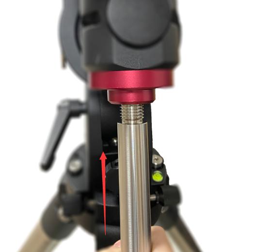
- Install counterweight (CW) shaft: Unthread and remove the CW shaft from top of mount. Thread the CW shaft into the CW shaft mounting holes.
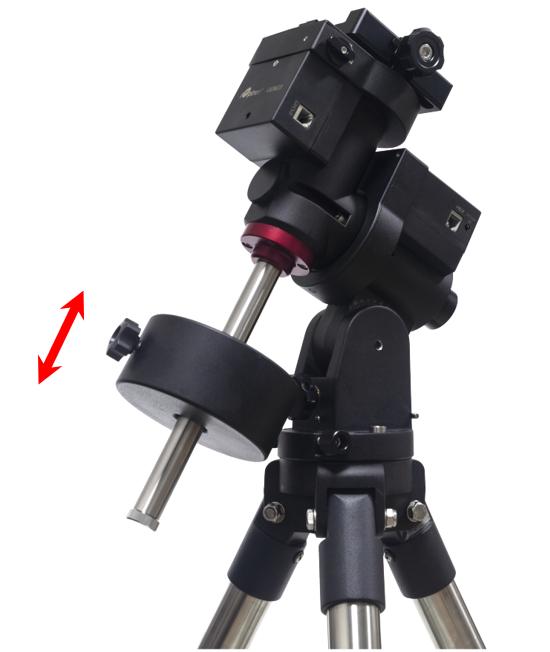
- Install counterweight: Before putting on CW, make sure the mount is at its zero position, i.e., CW shaft points to the ground. Insert Allen wrench to lock the RA axle and disengage the R.A. Gear Switch to set the R.A. axis free before loading the CW. Remove the CW Safety Cap at the end of CW Shaft. Glide the CW over the shaft with the larger hole opening facing down. Tighten the CW Locking Screw to hold the CW in place. Place the Safety Cap back onto the shaft. Move the CW to the bottom of the shaft and tighten the CW locking Screw.[TIP: GEM28 comes with a 10.4 lbs (4.7 kg) CW, which should be sufficient for an 8″ scope with total payloads up to about 13 lbs (6kg). Use extra CW or CW Extension Bar to balance higher payloads.]
- Install telescope: GEM28 has a Vixen dovetail saddle, with center adjusting block. Release the dovetail saddle locking knob and slide the telescope dovetail plate into the saddle. Tighten the saddle locking knob.
- Balance payload: After attaching the scope and accessories, the mount head assembly must be balanced in both DEC and RA axes to ensure minimum stresses on the mount driving mechanism.CAUTION: The telescope may swing freely when the R.A. or DEC Gear Switch is disengaged. Always hold on to the mount and/or telescope assembly before releasing the Gear Switches to prevent it from swinging, which can cause personal injuries and/or equipment damages.Set the mount at Zero Position. Disengage both RA and DEC gear switches and move the mount to horizontal position to check balance. Return to Zero Position for balance adjustment. Balance the DEC axis by moving the scope with accessories back and forth in the mount saddle or within the scope mounting rings. Balance the assembly in R.A. axis by moving CW along its shaft. Repeat the process until both DEC and RA axes are balanced.CAUTION: The balancing process MUST be done with Gear Switch at the total disengaged position! Otherwise it might damage the worm system.Return the mount to Zero Position after balancing and engage gear switches.
- Connect cables: Use the short RJ11 cable to connect the DEC control unit to the DEC port of the RA/main control unit.Connect the Go2Nova® 8409 Hand Controller to the HBX port on the main unit. Plug in a 12V DC power supply to the DC12V IN socket next to the HBX port.Plug optional GPS module into the iPORT with a coiled cable. When powering on, GPS ON sign should be displayed at the upper right corner of the hand controller. You may disconnect the GPS module after it picks up satellites signals and displays GPS OK. (It takes about 1 to 2 minutes in normal conditions).
- Set controller: Press the MENU button; then “Settings” => “Set Time & Site”.2020-10-01 12:01:36UTC -300 Minute(s)W071d08m50s DST: YN42d30m32s NorthernEnter the current date or waiting for the GPS connected to the satellites. Enter the time zone offset to the UTC; for examples:• Boston is “UTC -300 minutes”• Los Angeles is “UTC -480 minutes”• Rome is “UTC +060 minutes”• Sydney is “UTC +600 minutes”Toggle the Daylight Saving Time (DST) between N(No) and Y(Yes) using arrow key. Move the cursor to the end of screen to select the Northern or Southern Hemisphere.[TIPS: All time zones in N. America are “UTC -XXX minutes”. Latitude and longitude coordinates can be obtained from GPS-equipped devices (navigator, phone), or from internet, if you are entering them manually. “W/E” = western/eastern hemisphere; “N/S” = northern/southern hemisphere; and “d” = degree; “m” = minute; and “s” = second. Use arrow and number keys to enter location information.]
- Polar alignment: A GEM28 mount may be equipped with an iPolarTM electronic polar scope or an AccuAlignTM optical polar scope. Please refer to GEM28 User’s Manual for detailed polar alignment procedures.iPolar Polar AlignmentFor a GEM28 with an iPolar, refer to iPolar Operation Manual from iOptron’s website to perform the polar alignment, or steps briefly outlined below:• Download and install iPolar Software (first time use);• Connect a mini USB cable between the iPolar and a computer USB port;• Click Connect and start polar alignment by following on screen instructions.Quick Polar AlignmentFast and accurate polar alignment can be performed for a mount with an AccuAlignTM optical polar scope.(1) Thread polar scope LED onto the polar scope. Connect the LED cable between the LED and DC12V OUT socket from the DEC unit.(2) Use the Hand Controller (MENU => “Align” => “Pole Star Position”) to display the Polaris Position on the LCD screen, as indicated in the left side of the figure below. For example, June 22, 2014, 20:19:42 in Boston, US (alt N42°30’32” and long W71°08’50”), 300 min behind UT, the Polaris Position is 0h45.8m and 40.4m.(3) Use the Azimuth and Latitude Adj. Knobs to adjust the mount in both directions and put the Polaris in the location on the Polar Scope Dial (same as indicated on the HC LCD), as shown in the right side of the above figures.BrightStar Polar AlignmentWhen the pole star is not in sight, refer to online Instruction Manual for BrightStar Polar Alignment.
- Manual operation: The mount can now be used to observe astronomical objects with the HC. Use arrow keys to point the telescope to the desired object. Use the number keys to change the slewing speed. Press STOP/0 button to start tracking.
- Set Zero Position: The Set Zero Position command registers the current position as zero position. So before registering, the mount should be physically set at Zero Position either manually or slewed by hand controller. The Zero Position is defined as the telescope being on top of the mount head and pointing to North Pole, with CW shaft pointing to the ground. To register, press MENU => Zero Position => Set Zero Position. Press ENTER to confirm. One can also use MENU => Zero Position => Search Zero Position to set the Zero Position.
- One Star Alignment: Perform One Star Align to correct the Zero Position discrepancy and improve GOTO accuracy. Refer to User’s Manual for more details about improving GOTO accuracy.
- Go to an object: The mount is now ready for GOTO and tracking targets. Press MENU, select and ENTER Select and Slew. Select a category (e.g., Solar System), then select an object of interest (e.g., Moon). Press ENTER and the telescope will slew to the object and automatically start tracking.
- Sync to Target: If the object is not in the center of the eyepiece, use this function to center and synchronize the object to improve local GOTO accuracy. Press MENU and select and ENTER Sync to Target. Follow the on-screen instruction to perform the sync.[TIP: After slewing to an object, a list of nearby bright object(s) can be displayed by pressing the ? button.]
- Put the mount back into the package/carrying case: It is recommended to return the mount to Zero Position at the end of the observing session. Lay the mount into the carrying case. Disengage the gear system for transportation. Insert Allen wrench to lock the RA axis.Use [email protected] for technical supports.
 Rotate the mount head to normal position.
 Level the mount by adjusting the tripod legs. Use the build-in Bubble Level Indicator or an external leveler for this purpose.
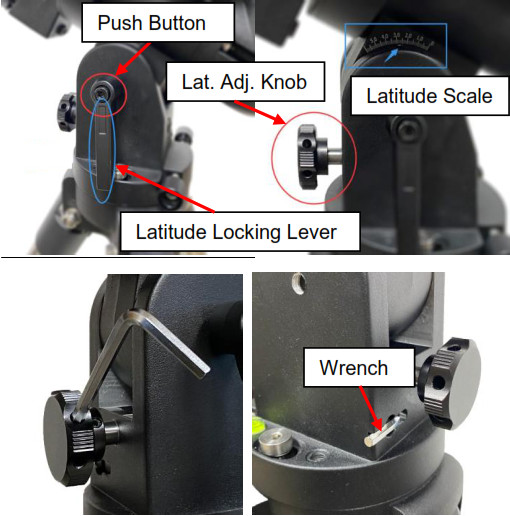
 [TIP: GEM28 comes with a 10.4 lbs (4.7 kg) CW, which should be sufficient for an 8″ scope with total payloads up to about 13 lbs (6kg). Use extra CW or CW Extension Bar to balance higher payloads.]
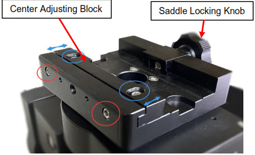
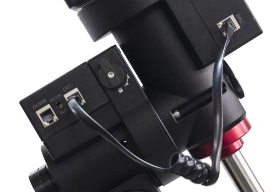 Connect the Go2Nova® 8409 Hand Controller to the HBX port on the main unit. Plug in a 12V DC power supply to the DC12V IN socket next to the HBX port.
 Plug optional GPS module into the iPORT with a coiled cable. When powering on, GPS ON sign should be displayed at the upper right corner of the hand controller. You may disconnect the GPS module after it picks up satellites signals and displays GPS OK. (It takes about 1 to 2 minutes in normal conditions).
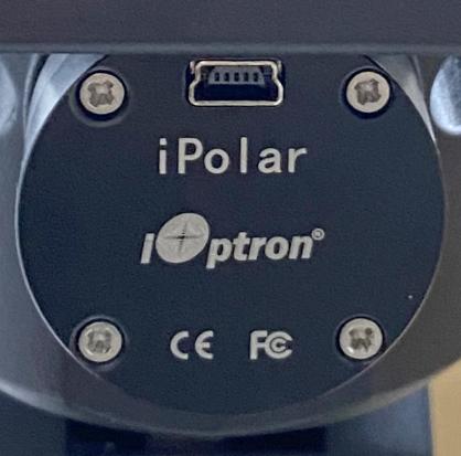 • Click Connect and start polar alignment by following on screen instructions.Quick Polar AlignmentFast and accurate polar alignment can be performed for a mount with an AccuAlignTM optical polar scope.(1) Thread polar scope LED onto the polar scope. Connect the LED cable between the LED and DC12V OUT socket from the DEC unit.
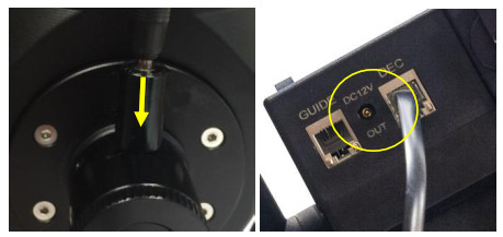 (2) Use the Hand Controller (MENU => “Align” => “Pole Star Position”) to display the Polaris Position on the LCD screen, as indicated in the left side of the figure below. For example, June 22, 2014, 20:19:42 in Boston, US (alt N42°30’32” and long W71°08’50”), 300 min behind UT, the Polaris Position is 0h45.8m and 40.4m.
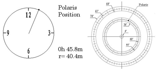 (3) Use the Azimuth and Latitude Adj. Knobs to adjust the mount in both directions and put the Polaris in the location on the Polar Scope Dial (same as indicated on the HC LCD), as shown in the right side of the above figures.BrightStar Polar AlignmentWhen the pole star is not in sight, refer to online Instruction Manual for BrightStar Polar Alignment.
IOPTRON TWO YEAR TELESCOPE, MOUNT, AND CONTROLLER WARRANTY
A. iOptron warrants your telescope, mount, or controller to be free from defects in materials and workmanship for two years. iOptron will repair or replace such product or part which, upon inspection by iOptron, is found to be defective in materials or workmanship. As a condition to the obligation of iOptron to repair or replace such product, the product must be returned to iOptron together with proof-ofpurchase satisfactory to iOptron.B. The Proper Return Merchant Authorization Number must be obtained from iOptron in advance of return. Call iOptron at 1.781.569.0200 to receive the RMA number to be displayed on the outside of your shipping container. All returns must be accompanied by a written statement stating the name, address, and daytime telephone number of the owner, together with a brief description of any claimed defects. Parts or product for which replacement is made shall become the property of iOptron.The customer shall be responsible for all costs of transportation and insurance, both to and from the factory of iOptron, and shall be required to prepay such costs.iOptron shall use reasonable efforts to repair or replace any telescope, mount, or controller covered by this warranty within thirty days of receipt. In the event repair or replacement shall require more than thirty days, iOptron shall notify the customer accordingly. iOptron reserves the right to replace any product which has been discontinued from its product line with a new product of comparable value and function.This warranty shall be void and of no force of effect in the event a covered product has been modified in design or function, or subjected to abuse, misuse, mishandling or unauthorized repair. Further, product malfunction or deterioration due to normal wear is not covered by this warranty.IOPTRON DISCLAIMS ANY WARRANTIES, EXPRESS OR IMPLIED, WHETHER OF MERCHANTABILITY OF FITNESS FOR A PARTICULAR USE, EXCEPT AS EXPRESSLY SET FORTH HERE. THE SOLE OBLIGATION OF IOPTRON UNDER THIS LIMITED WARRANTY SHALL BE TO REPAIR OR REPLACE THE COVERED PRODUCT, IN ACCORDANCE WITH THE TERMS SET FORTH HERE. IOPTRON EXPRESSLY DISCLAIMS ANY LOST PROFITS, GENERAL, SPECIAL, INDIRECT OR CONSEQUENTIAL DAMAGES WHICH MAY RESULT FROM BREACH OF ANY WARRANTY, OR ARISING OUT OF THE USE OR INABILITY TO USE ANY IOPTRON PRODUCT. ANY WARRANTIES WHICH ARE IMPLIED AND WHICH CANNOT BE DISCLAIMED SHALL BE LIMITED IN DURATION TO A TERM OF TWO YEARS FROM THE DATE OF ORIGINAL RETAIL PURCHASE.Some states do not allow the exclusion or limitation of incidental or consequential damages or limitation on how long an implied warranty lasts, so the above limitations and exclusions may not apply to you.This warranty gives you specific legal rights, and you may also have other rights which vary from state to state.iOptron reserves the right to modify or discontinue, without prior notice to you, any model or style telescope.If warranty problems arise, or if you need assistance in using your telescope, mount, or controller contact:
iOptron CorporationCustomer Service Department6F Gill Street Woburn, MA 01801www.ioptron.com[email protected]Tel. (781)569-0200Fax. (781)935-2860Monday-Friday 9AM-5PM EST
NOTE: This warranty is valid to U.S.A. and Canadian customers who have purchased this product from an authorized iOptron dealer in the U.S.A. or Canada or directly from iOptron. Warranty outside the U.S.A. and Canada is valid only to customers who purchased from an iOptron Distributor or Authorized iOptron Dealer in the specific country. Please contact them for any warranty.6 iOptron Corp. | 6E Gill Street | Woburn, MA 01801 USA | (781) 569-0200 | Toll Free (866) 399-4587 | www.iOptron.com
References
[xyz-ips snippet=”download-snippet”]