S-0001-006 Smart Connect KNX VAILLANT gateway set
ise smart connect KNX Vaillant Product ManualProduct Manualise smart connect KNX VaillantOrder No. S-0001-006 Complete set for installation, consisting of the two system components: – ise smart connect KNX Vaillant and – ise eBUS Adapter Order No. 1-0006-007 – ise smart connect KNX Vaillant Order No. 2-0001-003 – ise eBUS Adapter Valid for application software version 2.0 and firmware version 2.0Date of documentation 05/05/2021
Contents
ise smart connect KNX Vaillant Product Manual
1
Product description ………………………………………………………………………………………………….. 4
1.1 Functions ………………………………………………………………………………………………………………….. 4 1.2 Vaillant goes KNX ………………………………………………………………………………………………………. 5 1.3 Definitions and explanation of terms ……………………………………………………………………………… 5 1.4 Function schematic …………………………………………………………………………………………………….. 6 1.5 Usage scenarios Comfort solutions with KNX and Vaillant …………………………………………….. 71.5.1 Your presence controls the heating ………………………………………………………………………… 7 1.5.2 Controlling hot water and heating as needed……………………………………………………………. 7 1.5.3 Adjusting heating and hot water to special situations ………………………………………………… 7 1.5.4 Controlling ventilation……………………………………………………………………………………………. 7 1.6 Obtaining information from the Vaillant system……………………………………………………………….. 8 1.6.1 Preparing information on energy yield …………………………………………………………………….. 8 1.6.2 Energy consumption at a glance …………………………………………………………………………….. 8 1.6.3 Display heating status …………………………………………………………………………………………… 8 1.6.4 Heating active/inactive ………………………………………………………………………………………….. 8 1.6.5 Display water pressure………………………………………………………………………………………….. 8 1.6.6 Informed in detail………………………………………………………………………………………………….. 8
2
Installation, electrical connection and operation………………………………………………………… 9
2.1 Device design ise smart connect KNX Vaillant ……………………………………………………………….. 9 2.2 Safety notes …………………………………………………………………………………………………………….. 10 2.3 Installation and electrical connection …………………………………………………………………………… 10 2.4 Device design ise eBUS Adapter ………………………………………………………………………………… 12 2.5 Connecting the ise eBUS Adapter to the eBUS …………………………………………………………….. 13
3
Configuration………………………………………………………………………………………………………….. 15
3.1 Configuration step 1 – Create ise smart connect KNX Vaillant as device in the ETS………….. 16 3.2 Configuration step 2 Assigning an individual address………………………………………………….. 16 3.3 Configuration step 3 Setting the IP address, subnet mask and address of the defaultgateway…………………………………………………………………………………………………………………… 16 3.4 Setting general parameters………………………………………………………………………………………… 183.4.1 System dimensioning parameters …………………………………………………………………………. 18 3.4.2 Parameters use cases ………………………………………………………………………………………… 21 3.4.3 Time settings ……………………………………………………………………………………………………… 22 3.5 Connecting group addresses to group communication objects ……………………………………….. 23
4
Commissioning ………………………………………………………………………………………………………. 67
4.1 Operation ………………………………………………………………………………………………………………… 67 4.2 LED status displays…………………………………………………………………………………………………… 684.2.1 LED status display upon device start-up ………………………………………………………………… 68 4.2.2 LED status display in operation…………………………………………………………………………….. 69 4.3 Accelerate transfer: Select transfer path KNX-TP or IP ………………………………………………….. 70 4.4 Downloading the individual address of the device …………………………………………………………. 70 4.5 Transferring application programs and configuration data ………………………………………………. 71 4.6 Factory reset ……………………………………………………………………………………………………………. 71 4.6.1 Factory reset using the programming button on the device ………………………………………. 71 4.6.2 Factory reset using the website of the device …………………………………………………………. 71 4.7 Firmware update of the device……………………………………………………………………………………. 72 4.7.1 Firmware update using the device website …………………………………………………………….. 72
Order No. S-0001-006
Product Manual Page 2 (81)
ise smart connect KNX Vaillant Product Manual
4.7.2 Local firmware update without internet access ……………………………………………………….. 72 4.7.3 Compatibility of catalogue entry with firmware ………………………………………………………… 72
5
Technical data ………………………………………………………………………………………………………… 73
5.1 ise smart connect KNX Vaillant…………………………………………………………………………………… 73 5.2 ise eBUS Adapter……………………………………………………………………………………………………… 74
6
Frequently asked questions (FAQ)…………………………………………………………………………… 75
7
Troubleshooting and support ………………………………………………………………………………….. 76
7.1 Downloading log files if a problem occurs…………………………………………………………………….. 76 7.2 Status page of the ise smart connect KNX Vaillant………………………………………………………… 76 7.3 The ise smart connect KNX Vaillant does not work ……………………………………………………….. 77
8
ise smart connect KNX Vaillant software licence agreement …………………………………….. 78
8.1 Definitions ……………………………………………………………………………………………………………….. 78 8.2 Object of the agreement…………………………………………………………………………………………….. 78 8.3 Rights of use of the ise smart connect KNX Vaillant software …………………………………………. 78 8.4 Restriction of rights of use………………………………………………………………………………………….. 788.4.1 Copying, modification and transmission…………………………………………………………………. 78 8.4.2 Reverse engineering and conversion technologies …………………………………………………. 78 8.4.3 Firmware and hardware ………………………………………………………………………………………. 79 8.4.4 Transfer to a third party ……………………………………………………………………………………….. 79 8.4.5 Renting out, leasing out and sub-licensing …………………………………………………………….. 79 8.4.6 Software creation ……………………………………………………………………………………………….. 79 8.4.7 The mechanisms of license management and copy protection …………………………………. 79 8.5 Ownership, confidentiality ………………………………………………………………………………………….. 79 8.5.1 Documentation …………………………………………………………………………………………………… 79 8.5.2 Transfer to a third party ……………………………………………………………………………………….. 79 8.6 Changes, additional deliveries ……………………………………………………………………………………. 79 8.7 Warranty …………………………………………………………………………………………………………………. 79 8.7.1 Software and documentation ……………………………………………………………………………….. 80 8.7.2 Limitation of warranty ………………………………………………………………………………………….. 80 8.8 Liability ……………………………………………………………………………………………………………………. 80 8.9 Applicable law ………………………………………………………………………………………………………….. 80 8.10 Termination ……………………………………………………………………………………………………………… 80 8.11 Subsidiary agreements and changes to the agreement………………………………………………….. 81 8.12 Exception ………………………………………………………………………………………………………………… 81
Order No. S-0001-006
Product Manual Page 3 (81)
ise smart connect KNX VaillantProduct description1 Product description1.1 Functions· Operating a sensoCOMFORT or multiMATIC-controlled Vaillant1 heating and domestic hot water system using KNX2.· Control of heating and cooling function, hot water and ventilation with the usual KNX operating de-vices regardless of heating control unit.· Easy connection of visualisation systems and facility management systems. · Changes made using the heating system controller are reported on the KNX.· Supports accelerated transmission from the ETS2 to the ise smart connect KNX Vaillant via a direct IP connection.· The ise smart connect KNX Vaillant is configured using the latest version of the ETS5. The application accesses ETS functions not supported by earlier ETS versions.· Together with the ise eBUS Adapter, the ise smart connect KNX Vaillant establishes the connection between the smart heating control and your KNX system.Important note: The use of both system components is required to ensure functioning control. The ise smart connect KNX Vaillant can therefore only be used in conjunction with the ise eBUS Adapter. The system components can be ordered as a set or individually (for replacement purposes). The Vaillant heating system must be controlled using a sensoCOMFORT or multiMATIC system controller. Other system controllers are not compatible. The term system controller is used for both variants in the rest of this manual.Important! The device must be supplied with voltage by a dedicated power supply unit. Do not use the auxiliary voltage output of a KNX power supply unit which is also supplying a KNX line.Important note: The product comes with a handover protocol in German and English. The HVAC supplier must document installation on the handover protocol and hand it to the planner for building technology (KNX bus system). The handover protocol is available in other languages on the website at www.ise.de/en/home.
1 Vaillant is a registered trademark of Vaillant Deutschland GmbH & Co. KG 2 ETS and KNX are registered trademarks of KNX Association cvbaOrder No. S-0001-006
Product Manual Page 4 (81)
ise smart connect KNX VaillantProduct description1.2 Vaillant goes KNXThe ise smart connect KNX Vaillant enables you to implement innovative solutions for your intelligent home.Connecting KNX and Vaillant opens up new possibilities: · Your presence and absence control the heating. · Operating devices in every room desired enable convenient access to your Vaillant system. · “Instant” hot water can be requested using a sensor or an operating device in the room in question. · Integration of heating and/or ventilation in building scenarios.These and other application examples can be found in more detail in chapter 1.5 “Use scenarios Comfort solutions with KNX and Vaillant”.1.3 Definitions and explanation of terms· ise eBUS Adapter The ise eBUS Adapter is a system component used to connect the Vaillant bus modular control system with the KNX system. The eBUS adapter connects ise smart connect series devices for the eBUS connection, in this case, ise smart connect KNX Vaillant, and the Vaillant controller with one another via a USB interface. The eBUS adapter is a specially designed system component for these specific use cases. Any other use or use beyond this purpose is considered improper.· Vaillant system All components of the Vaillant heating system are designated as the Vaillant system. One of these components must be a system controller with which the ise smart connect KNX Vaillant communicates. This can also be the radio module in the system controller.Information on the operation, installation and any required accessories can be found in the corresponding documents issued by Vaillant.· eBUS The commands generated by KNX devices are prepared via the ise smart connect KNX Vaillant and the ise eBUS Adapter to enable communication with the central system controls the Vaillant system via the eBUS. Separate addressing of ise system components for the eBUS is not necessary.The eBUS connection point is described in chapter 2.5 “Connecting the ise eBUS Adapter to the eBUS”. The relevant instructions for installation on the eBUS provided by Vaillant (connection procedures, cable selection etc.) must be observed.
Order No. S-0001-006
Product Manual Page 5 (81)
1.4 Function schematic
ise smart connect KNX VaillantProduct description
ise smart connect KNX Vaillant
ise eBUS Adapter
Order No. S-0001-006
Product Manual Page 6 (81)
ise smart connect KNX VaillantProduct description1.5 Usage scenarios Comfort solutions with KNX and VaillantEnhance the existing Comfort functions of your KNX system and smart heating and domestic hot water control.1.5.1 Your presence controls the heatingYou won’t be at home for a longer period of time. KNX enables you to perform an occupied-home simulation today, allowing you to conveniently activate the alarm system by pressing the “absence switch”. You can now also use the ise smart connect KNX Vaillant to switch your heating system to “standby mode”. This allows you to reduce the room temperature setpoint values in all rooms (if desired) and minimise heating.1.5.2 Controlling hot water and heating as neededYou want to be able to enter and change the times and setpoint values for heating and hot water in your visualisation or any other operating device quickly and easily. This means you can save energy without renouncing comfort. After all, the system only works when you need it.1.5.3 Adjusting heating and hot water to special situationsYou want to be able to react to short-term changes in use quickly and easily (longer than usual periods of absence, events, parties, etc.). With the ise smart connect KNX Vaillant, you can temporarily change the times and setpoint values for heating and hot water. After this period, your standard values apply once again.1.5.4 Controlling ventilationAdapt the ventilation system to meet your needs. Start modes such as ventilation boost at the push of a button.
Order No. S-0001-006
Product Manual Page 7 (81)
ise smart connect KNX VaillantProduct description1.6 Obtaining information from the Vaillant system1.6.1 Preparing information on energy yieldPrepare information on the energy yield of the heat pumps and/or solar system to create a clear overview of the energy generation on your visualisation. Note that this information must be provided by the components used in the heating system.1.6.2 Energy consumption at a glancePrepare information on the energy consumption to create a constant overview of consumption on your visualisation (or other display). Recognise changes and adapt the control to changed usage behaviour if necessary. Note that this information must be provided by the components used in the heating system.1.6.3 Display heating statusPrepare information on your heating system to create a constant overview of the system on your visualisation. This enables you to react immediately in the event of a fault.1.6.4 Heating active/inactiveCheck whether the heating is currently active at any time via your visualisation.1.6.5 Display water pressureReceive an alarm signal for insufficient water pressure. Select the signalling in a manner and location that allows you to react quickly.1.6.6 Informed in detailWhether you are on the sofa or looking at the panel, you can read important data such as the hot water temperature, the circulation pump status or the minimum setpoint flow temperature for cooling mode quickly and clearly on your KNX visualisation display.
Order No. S-0001-006
Product Manual Page 8 (81)
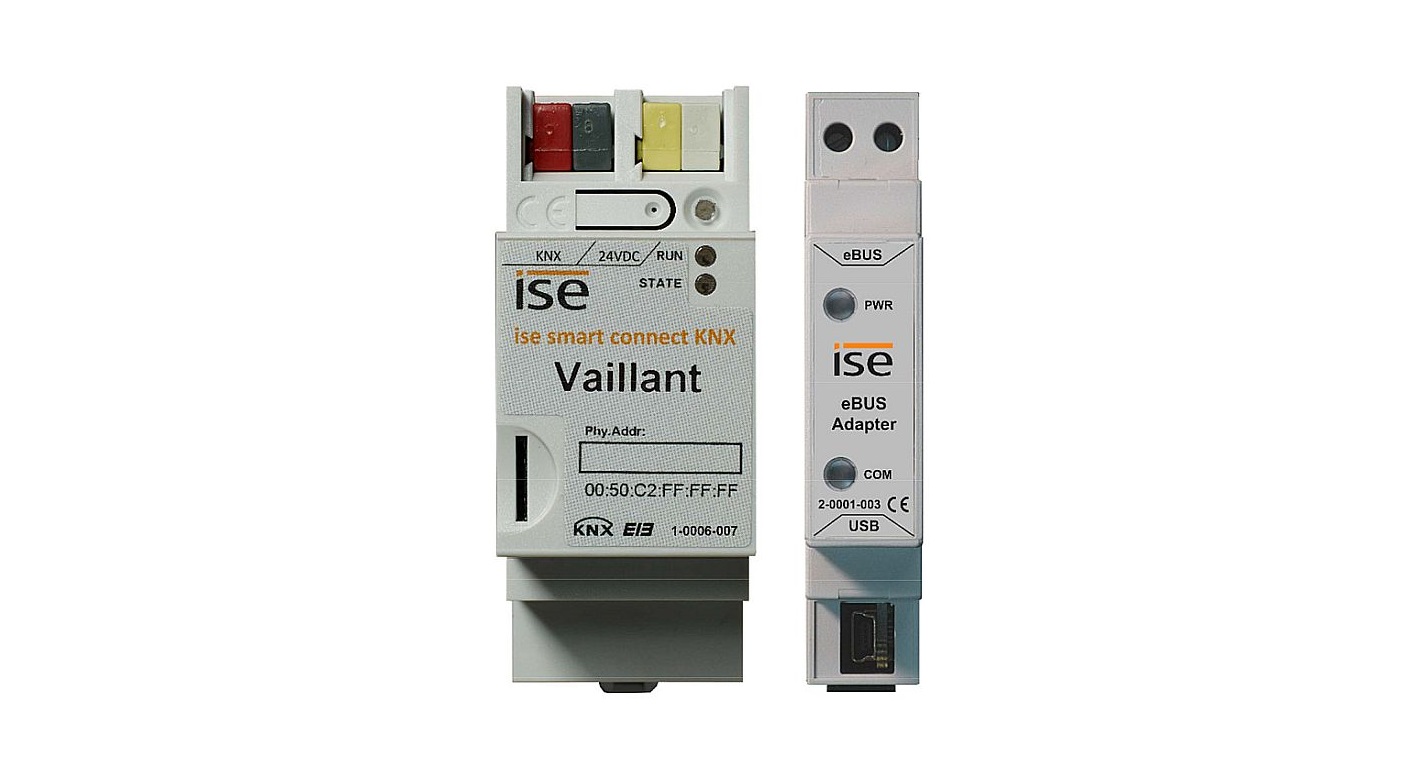
ise smart connect KNX VaillantInstallation, electrical connection and operation2 Installation, electrical connection and operation2.1 Device design ise smart connect KNX VaillantDimensions: Width (W): 36 mm (2 HP) Height (H): 90 mm Depth (D): 74 mm
Figure 1: ise smart connect KNX Vaillant
1
Programming button for KNX
2
KNX connection (twisted pair)
3
Connection for power supply
4
KNX programming LED (red)
5 LED APP (green)
6 LED COM (yellow)
7 Ethernet connection
8 USB connection 9 microSD card slot
Switches the device to the ETS programming mode or vice versa.
Left: ( + / red) Right: ( – / black)DC 24 to 30 V, 2 W (at 24 V) Left: ( + / yellow) Right: ( – / white)
Red: Device is in ETS programming mode
Green: Normal operation
Off / flashes:
See 4.2.1 / 4.2.2 for start or diagnosis code
Yellow: Normal operation (brief dark phases indicate KNX telegram
traffic)
Off /
flashes:
See 4.2.1 / 4.2.2 for start or diagnosis code
LED 10/100 speed (green)
On: 100 Mbit/s
Off:
10 Mbit/s
LED link/ACT (orange)
On:
Connection to IP network
Off:
No connection
Flashes: Data reception on IP
USB connection type A; establishes the connection to the Vaillant system via the ise eBUS Adapter. Use the supplied USB cable as standard. Please note that the use of USB cables with a length of more than 3 m is generally not permitted.
Without function.
Order No. S-0001-006
Product Manual Page 9 (81)
ise smart connect KNX VaillantInstallation, electrical connection and operation2.2 Safety notesElectrical devices may only be installed and mounted by a qualified electrician. In doing so, the applicable accident prevention regulations must be observed. Failure to observe the installation instructions can result in damage to the device, fire or other dangers.DANGER! Electric shock if live parts are touched. Electric shock may lead to death. Isolate connection cables before working on the device. Cover up live parts in the vicinity!IMPORTANT! The device must be supplied with voltage by a dedicated power supply unit. Do not use the auxiliary voltage output of a KNX power supply unit which is also supplying a KNX line.See the installation instructions enclosed with the device for more information.2.3 Installation and electrical connectionInstalling the device The device is intended for fixed installation in indoor spaces and dry rooms. Snap it on to the top-hat rail as per DIN EN 60715, vertical installation; network connections mustface downward. A KNX data rail is not required; the connection to KNX-TP is established using the accompanying bus connection terminal. Observe temperature range (0 °C to +45 °C); do not install over heat-emitting devices and ensure sufficient ventilation/cooling if necessary.Connecting the device Route the bus line with the sheathing intact until it is close to the bus connection terminal. Firmly press the bus line into the bus connection terminal as far as possible. Install bus line leads without sheathing (SELV) reliably disconnected from all non-safety low-voltagecables (SELV/PELV). Maintain the specified clearance. Attach the cover cap supplied. Also see also the VDE regulations governing SELV (DIN VDE 0100-410/”Safe separation”, KNX in-stallation regulation) for more information. Connect the external power supply to the device’s power supply connection (3) using a KNX deviceconnection terminal, preferably yellow/white. Polarity: left/yellow: (+), white/right: (-). Important: The device must be supplied with voltage by a dedicated power supply unit. Do not use the auxiliary voltage output of a KNX power supply unit which is also supplying a KNX line.
Order No. S-0001-006
Product Manual Page 10 (81)
ise smart connect KNX VaillantInstallation, electrical connection and operationConnect one IP network cable to the device’s network connection (7). Connect the USB interface (8) to the ise eBUS Adapter. Use the supplied USB cable as standard.Please note that the use of USB cables with a length of more than 3 m is generally not permitted. When connecting an active ise smart connect KNX Vaillant with the ise eBUS Adapter, the initialisation may require up to three minutes. During this time, the ise smart connect KNX Vaillant may restart. Note: The use of the ise smart connect KNX Vaillant requires the use of an ise eBUS Adapter. This can be ordered as a set or individually (as a replacement).Fitting/removing a cover cap A cover cap can be fitted to protect the KNX bus and power supply connections from dangerous voltages, particularly in the connection area. The cap is fitted with an attached bus and power supply terminal and a connected bus and power supply line to the rear.· Fitting the cover cap: The cover cap is pushed over the bus terminal until you hear and feel it lock into position (compare Figure 2: Fitting/removing a cover cap (A)).· Removing the cover cap: The cover cap is removed by pressing it in slightly on the side and pulling it off to the front (compare Figure 2: Fitting/removing a cover cap (B)).Figure 2: Fitting/removing a cover cap
Order No. S-0001-006
Product Manual Page 11 (81)
ise smart connect KNX VaillantInstallation, electrical connection and operation2.4 Device design ise eBUS Adapter1Dimensions: Width (W): 17.5 mm (1 HP) Height (H): 90 mm Depth (D): 58 mm 2
3
4
Figure 3: ise eBUS Adapter
1 eBUS connection 2 LED PWR (green) 3 LED COM (green)4 USB connection
Important note: The maximum length of the eBUS connection cable is 125 m. Please see chapter 2.5 “Connecting the ise eBUS Adapter to the eBUS” for the position of the eBUS connection.Green: Minimum voltage from eBUS is connectedGreen: Connection between ise smart connect KNX Vaillant with eBUS establishedImportant note: The adapter cable for the USB port is equipped with a mini USB-B angle plug. To prevent damage, the angled plug must always be pulled out toward the front.Use the supplied USB cable as standard. Please note that the use of USB cables with a length of more than 3 m is generally not permitted.
See the installation instructions enclosed with the device for more information.
Order No. S-0001-006
Product Manual Page 12 (81)
ise smart connect KNX VaillantInstallation, electrical connection and operation2.5 Connecting the ise eBUS Adapter to the eBUSThe heating technology supplier has installed a junction box in which an eBUS cable is laid from the heating system. The company installing the KNX system will establish the connection to the ise eBUS Adapter in this junction box.
Figure 4: Junction box for the connection of the ise eBUS Adapter to the heating system.The position of the junction box can be seen in the handover protocol from executing HVAC supplier to the building technology planner (KNX bus system). You can find the required information in Point 7 “Position of eBUS connection point between the Vaillant heating system and KNX Gateway”.Once the connection between the KNX system and the eBUS is established, the company installing the KNX system must attach the following sticker enclosed with the product to the Vaillant system:controlled byKNXFigure 5: Heating system marking.
Order No. S-0001-006
Product Manual Page 13 (81)
ise smart connect KNX VaillantInstallation, electrical connection and operationIt is recommended to attach the sticker here:Figure 6: Sticker attachment to BMU.
Order No. S-0001-006
Product Manual Page 14 (81)
ise smart connect KNX VaillantConfiguration
3 Configuration
Configuration of the ise smart connect KNX Vaillant system components is divided into the following
steps:
For explana-
Preparations:
tions, see
1 Installing ise eBUS Adapter. Connect the ise smart connect KNX Vaillant
with the ise eBUS Adapter via the USB interface. Use the supplied USB cable as standard. Please note that the use of USB
Chapter 2
cables with a length of more than 3 m is generally not permitted.
2 Mount ise smart connect KNX Vaillant; connect to KNX bus connection and
auxiliary power.
Important note: The device must be supplied with voltage by a dedicated
Chapter 2.3
power supply unit. Do not use the auxiliary voltage output of a KNX power
supply unit which is also supplying a KNX line.
3 Connect the ise eBUS Adapter with the eBUS in the designated junction box. Important note: The maximum length of the eBUS connection cable is 125 m.
Chapter 2.5
4 If necessary, install the ise smart connect KNX Vaillant on the IP network and make settings on the IP network router where required.
Configuration via ETS:
The device can be put into operation after installing the device and connecting the bus, power supply and, if necessary, Ethernet. The preparatory configuration is carried out using the Engineering Tool Software, ETS, available from the KNX Association, see www.knx.org.
1 Create the ise smart connect KNX Vaillant as a device in the ETS.
Chapter 3.1
2 Assign individual address as usual as appropriate for the KNX topology.
3 Set IP address, IP subnet mask and default gateway address on the ise smart connect KNX Vaillant or select “Obtain an IP address automatically (from a DHCP server)”.
Chapter 3.3
4 General parameters for setting the ise smart connect KNX Vaillant.
Chapter 3.4.1
5 Connect group addresses to communication object as usual.6 The ise smart connect KNX Vaillant is now ready for commissioning via “Download ETS” and for testing of the functions.
Chapter 3.5
Order No. S-0001-006
Product Manual Page 15 (81)
ise smart connect KNX VaillantConfiguration
3.1 Configuration step 1 – Create ise smart connect KNX Vaillant as device in the ETSIf you have not already done so, import the ETS device application to the ise smart connect KNX Vaillant once in the device catalogue of its ETS, for example using the “Import products” function on the start page of the ETS.
You can download the ETS application from our website under www.ise.de/en/home free of charge.
The other explanations in this document refer to
Hardware
Device: ise smart connect KNX Vaillant
Manufacturer: ise GmbH
Order no.: 1-0006-007
Version:
V1.0
Design:
DRA (series installation)
Application software
Application: ise smart connect KNX Vaillant
Version:
V2.0
If you already have an ETS project with a previous database entry, you can also update the application program. To do this, drag the new database entry to the project and then select the device with the old database entry. Now select “Information” in the device “Properties” and then select the “Application”tab.There, you can use the “Update” button to replace the old database entry. Existing links with group addresses are not lost. The newly added device can now be deleted again.
3.2 Configuration step 2 Assigning an individual addressIn the ETS, assign the device an individual address as usual as appropriate for the KNX topology.
3.3 Configuration step 3 Setting the IP address, subnet mask and address of the default gatewayIn addition to the individual address on the KNX network, the ise smart connect KNX Vaillant can also be assigned an address on the IP data network. This includes the following information:· IP address, · subnet mask and the · address of the default gateway.This can occur in two ways, either · automatically by obtaining the data from a DHCP server (e.g. integrated in the router of the data network) or · making a manual setting in the ETS.
Order No. S-0001-006
Product Manual Page 16 (81)
Proceed as follows for this purpose: 1. Select the device in the ETS.
ise smart connect KNX VaillantConfiguration
2. Display the device properties in the sidebar onthe ETS as shown in Figure 7: ETS device properties dialogue.
Figure 7: ETS device properties dialogue.
3. Select the “IP” tab according to Figure 8. Then select eitherObtain an IP address automatically (default)
The address data are automatically obtained from a DHCP server on the data network.
or Use a static IP address
and enter the data manually. You can usually obtain the permitted IP address range and the subnet mask and standard gateway from the router configuration interface.If the Obtain an IP address automatically setting is used, a DHCP server must issue a valid IP address to the ise smart connect KNX Vaillant.
Figure 8: Setting for the device’s IP address data on the “IP” tab in the sidebar ofthe ETS.
If a DHCP server is not available for this setting, thedevice starts up after a waiting time with an AutoIP address (address range from 169.254.1.0 to 169.254.254.255).
As soon as a DHCP server is available, the device is automatically assigned a new IP address.
Order No. S-0001-006
Product Manual Page 17 (81)
ise smart connect KNX VaillantConfiguration
3.4 Setting general parameters3.4.1 System dimensioning parametersIn the first part of the parametrisation, a prompt is given for system dimensioning. Take the system dimensioning from the handover protocol from the HVAC supplier. However, if you have updated the ETS application, check the system dimensioning and complete the handover protocol if necessary.Individual components are requested separately. The default value of each parameter is marked in bold.
System dimensioning
Components
Entry / Selec-tion
Remarks
Heat generator
A Vaillant gas boiler is available
Yes No
Heat generator
A Vaillant heat pump is available
Yes No
Solar thermal sys- A solar thermal system is available, the data
tem
from which the system controller records
Solar thermal system
A Vaillant VMS or VPM-S is available
Ventilation
A Vaillant recoVAIR domestic ventilation unit is available, which is controlled by the systemcontroller
Heat generator
Heat generator 1 is available
Yes NoOnly visible if Yes yes was the anNo swer to the pre-vious point.Yes NoYes No
Heat generator
Heat generator 2 is available
Yes No
Heat generator
Heat generator 3 is available
Yes No
Heat generator
Heat generator 4 is available
Yes No
Heat generatorHeat generator Order No. S-0001-006
Heat generator 5 is available Heat generator 6 is available
Yes NoProduct Manual Page 18 (81)
System dimensioning
Components
ise smart connect KNX VaillantConfiguration
Entry / Selec-tion Yes No
Remarks
Heat generator
Heat generator 7 is available
Yes No
Heat generator
Heat generator 8 is available
Yes No
Heating circuit 1
A heating circuit 1 is available for room heating
Yes No
”
The cooling function for circuit 1 is activated
Yes
on the system controller
No
Heating circuit 2
A heating circuit 2 is available for room heating
Yes No
”
The cooling function for circuit 2 is activated
Yes
on the system controller
No
Heating circuit 3
A heating circuit 3 is available for room heating
Yes No
”
The cooling function for circuit 3 is activated
Yes
on the system controller
No
Hot water
Hot water is controlled via the system control-
Yes
ler
No
”
A Vaillant VPM-W domestic hot water unit is
Yes
available in the system
No
”
A mixer circuit is configured as a cylinder charging circuit for hot water cylinder charg-ing
Yes No
Order No. S-0001-006
Product Manual Page 19 (81)
ise smart connect KNX VaillantConfiguration
System dimensioning
Components
Sensors
The automatic date/time functions at the system’s location
Entry/Selection
Remarks
Yes No
”
The system controller shows the fuel consumption (gas consumption) in the “Infor-mation” menu
Yes No
”
The system controller shows the consumption (electricity consumption) in the “Infor-mation” menu
Yes No
”
The system controller shows the water pres-
Yes
sure in the “Information/System status” menu
No
”
The heating system should be re-filled with water if it falls below the following water pres-
0 bar
sure
Order No. S-0001-006
Product Manual Page 20 (81)
ise smart connect KNX VaillantConfiguration
3.4.2 Parameters use casesIn the second part of the parametrisation, a prompt is given for corresponding use cases. The possible use cases are already defined by the system dimensioning. Simply mark the cases you wish with a tick. No ticks are marked during the first call-up.
Note that all supported use cases appear in the following list. The actual use cases possible for a system depend on the system dimensioning. Only these will be offered by the ETS.
Rubric Smart control””” Information” ” ”
Use casesI would like “Standby” activation in my home, so I can also switch my heating to “Standby”. I would like to be able to configure hot water heating and heating in my visualisation with time control. I always would like to carry out short-term changes to my regular heating and hot water control in order to maintain a pleasant room temperature and hot water during longer periods of presence (e.g. overtime in the office or party at home). I would like to be able to change the operation mode of the ventilation or switch the ventilation boost on/off in order to adapt the ventilation to my current requirements. I would like to see the energy yield of my heat pump and solar thermal system in my visualisation in order to monitor the overall yield of my system. I would like to be able to see the energy consumption of my Vaillant system in my visualisation in order to display the current value and historical diagrams. I would like to see the system status of my Vaillant system in my visualisation in order to have constant reassurance that everything is okay. I would like to see the current water pressure of the system in my visualisation and be able to activate an alarm if it becomes too low in order to be able to react to it.
Order No. S-0001-006
Product Manual Page 21 (81)
ise smart connect KNX VaillantConfiguration3.4.3 Time settingsThe time settings are made in the third part of parametrisation. You can enter the time intervals when the time and date are sent from the system controller to the KNX system under Clock. You select how the cooling time is to be set under Manual cooling function.The individual time settings are queried separately during this process. The default value of each parameter is marked in bold.
Rubric Clock
Time settings Send time
Entry/SelectionEvery minute Every hour Every day
”
Send date
Every minute Every hour Every day
Manual cooling function
Set cooling time
Number of cooling days Cooling interval
Order No. S-0001-006
Product Manual Page 22 (81)
ise smart connect KNX VaillantConfiguration3.5 Connecting group addresses to group communication objectsDifferent group objects are available for connecting group addresses on the ise smart connect KNX Vaillant. The visibility of the group communication object is dependent on the setting in the chapters 3.4.1 “System dimensioning parameters” and 3.4.2 “Parameters use cases”. Dependency is specified for each communication object in italics under “Description”.Note on querying status values on the system controller: · Communication objects whose query frequency is prioritised: The ise smart connect KNX Vaillant updates the information on the heating system’s status at regular intervals based on prioritisation. Any changes to the status are thus only identified during the next query. · Communication objects which are not subject to prioritisation: The ise smart connect KNX Vaillant updates the information based on events. Changes to the status are thus identified in real time. · It is possible that values are made available by the heating regulator for a longer period of time. This means that, even if the values are polled by the ise smart connect KNX Vaillant at shorter intervals, the values on the KNX bus do not change until updating occurs in the heating regulator. It may also be the case that values which have already been updated are shown on the controller’s display, but are not available to the ise smart connect KNX Vaillant yet. In addition to prioritisation, the updating time on the controller is also indicated for communication objects concerned.
Object1Rubric: Function:Description:Object2Rubric: Function:Description:
Name
Direction
Data width
DP type
System in service mode
Read
1 bit
Connections
Data type:
Indicates whether the system’s service mode is active. Cycle time: max. 5.5 minutes
This communication object is always visible.
1.011 Status
Flags (CRWTU)CR-T-
Name
Direction
Data width
DP type
Fault heating generator
Read
1 bit
1.002
Connections
Data type:
Boolean
Indicates whether one of the available heat generators has an error. Cycle time: max. 9 minutes
This communication object is always visible. True = Error exists
Flags (CRWTU)CR-T-
Order No. S-0001-006
Product Manual Page 23 (81)
Object3Rubric: Function:Description:Object4Rubric: Function:Description:Object5Rubric: Function:Description:Object6Rubric: Function: Description:
ise smart connect KNX VaillantConfiguration
NameTime
DirectionRead
Data width3 bytes
DP type10.001
Flags (CRWTU)CR-T-
Date/time
Data type:
Time of day
Provides the Vaillant system time Cycle time: max. 3 minutes Clock interval: Every minute/every hour/every dayThis communication object is visible when the automatic date/time configuration functions at the system’s location.Parameters > System dimensioning > Sensors > The automatic date/time functions at the system’s location <yes>
Name
Direction
Data width
Date
Read
3 bytes
Date/time
Data type:
Provides the Vaillant system date. Cycle time: max. 3 minutes Clock interval: Every minute/every hour/every day
DP type11.001 Date
Flags (CRWTU)CR-T-
This communication object is visible when the automatic date/time configuration functions at the system’s location.Parameters > System dimensioning > Sensors > The automatic date/time functions at the system’s location <yes>
NameOutside temperature Temperature
DirectionReadData type:
Data width
DP type
Flags (CRWTU)
2 bytes
9.001 CR-T-
Temperature (oC)
Provides the outside temperature. Cycle time: max. 3 minutes Value range > – 40 °C
This communication object is always visible.If the value is – 40 °C or lower, error code 7 is sent to group communication object 12. This can indicate a defect in the temperature sensor.
Name
Direction
Data width
DP type
System status “Standby”
ReadData type:
1 bit
Indicates whether the system is in “Standby” mode. Cycle time: max. 3 minutesThis communication object is always visible.
1.011 Status
Flags (CRWTU)CR-T-
Order No. S-0001-006
Product Manual Page 24 (81)
Object7Rubric: Function: Description:Object8Rubric: Function: Description:
ise smart connect KNX VaillantConfiguration
NameSystem status “Heating”
DirectionReadData type:
Data width
DP type
1 bit
1.011
Status
Flags (CRWTU)CR-T-
Indicates whether the system is in “Heating” mode. Cycle time: max. 3 minutesThis communication object is visible when a heating circuit is available and the corresponding use case has been selected.Parameters > System dimensioning > Heating circuit N > A heating circuit N is available for room heating <yes> and Parameters > Use cases > Information > I would like to see the system status of my Vaillant system (…) <>
NameSystem status “Cooling”
DirectionReadData type:
Data width
DP type
1 bit
1.011
Status
Flags (CRWTU)CR-T-
Indicates whether the system is in “Cooling” mode. Cycle time: max. 3 minutes
This communication object is visible when the Vaillant system is also to be used for cooling.The requirement for this is a heating circuit which has the cooling function activated and the corresponding use case has been selected.Parameters > System dimensioning > Heating circuit N > A heating circuit N is available for room heating <yes> and Parameters > System dimensioning > Heating circuit N > The cooling function for circuit N is activated in the system controller <yes> and Parameters > Use cases >Information > I would like to see the system status of my Vaillant system (…) <>
Order No. S-0001-006
Product Manual Page 25 (81)
Object9Rubric: Function: Description:Object10Rubric: Function:Description:
ise smart connect KNX VaillantConfiguration
NameSystem status “DHW”
DirectionReadData type:
Data width
DP type
1 bit
1.011
Status
Flags (CRWTU)CR-T-
Indicates whether the system is in “Hot water” mode. Cycle time: max. 3 minutes
This communication object is visible when the hot water is controlled by the system controller. Please note that if a VPM-W Vaillant domestic hot water unit is used or if a mixer circuit is configured as a cylinder charging circuit for the hot watercylinder charging, control via the system controller is not possible. This communication object is not visible in this case.
Parameters > System dimensioning > Hot water > Hot water is controlled via the system controller <yes> and Parameters > Use cases > Information > I would like to see the system status of my Vaillant system (…) <>
NameWater pressure
DirectionReadData type:
Data width
DP type
2 bytes
9.006
Pressure (Pa)
Flags (CRWTU)CR-T-
Displays the current water pressure of the system.Cycle time: max. 3 minutesValue range: 0670760 Pa (06.70760 bar) Replacement value: NaN (not a number) if the sensor is not available or is defective.
This communication object is visible when the current water pressure in the Vaillant system is to be displayed. The requirement for this is that the system controller must display the system pressure and the corresponding use case must be selected.Parameters > System dimensioning > Sensors > The system controller shows the water pressure in the “Information/System status” menu <yes> and Parameters > Use cases > Information > I would like to see the current water pressure of the system (…) <>If the system pressure exceeds the value of 6.70760 bar, error code 7 is sent to communication object 12.
Order No. S-0001-006
Product Manual Page 26 (81)
ise smart connect KNX VaillantConfiguration
Object11Rubric: Function: Description:Object12Rubric: Function: Description:
Name
Direction
Data width
DP type
KNX gateway error
Read
1 bit
Connections
Data type:
Indicates whether the KNX gateway has an error.
This communication object is always visible. True = Error exists
1.002 Boolean
Flags (CRWTU)CR-T-
NameLast KNX gateway error Error
DirectionReadData type:
Data width
DP type
1 bytes
20.*
1 byte
Flags (CRWTU)CR-T-
Error code of the last KNX gateway error
This communication object is always visible.1 = System controller not found. eBUS communication is possible, but no system controller was found.2 = Reserved for subsequent use.3 = Error in communication with the ise eBUS Adapter. Communication between the ise smart connect KNX Vaillant and the ise eBUS Adapter is not possible via USB.4 = eBUS cable is not connected. eBUS connection not recognised.5 = No answer from the eBUS. No answer to query from eBUS.6 = Value is not supported. There is no corresponding eBUS value for a KNX value.7 = Value not permitted. The received value is not within the permitted range (eBUS and KNX)LED status displays on the ise smart connect KNX Vaillant are allocated to the error codes 1 to 4. The corresponding values are described in chapter 4.2.2 “LED status display in operation”.
Order No. S-0001-006
Product Manual Page 27 (81)
Object13Rubric: Function:Description:
ise smart connect KNX VaillantConfiguration
NameHeating/Cooling
DirectionRead
Data width1 bit
DP type1.100
Flags (CRWTU)CR-T-
Data type:
Cooling/heating
Indicates whether the system is in “Heating” or “Cooling” mode. Cycle time: max. 3 minutes
1 = Heating (initial value)0 = CoolingThe requirement for this is the installation of a Vaillant heat pump, a heating circuit which has the cooling function activated and the corresponding use case has been selected.Parameters > System dimensioning > Heat generator > A Vaillant heat pump is available <yes> and Parameters > System dimensioning > Heating circuit N > A heating circuit N is available for room heating <yes> and Parameters > System dimensioning > Heating circuit N > The cooling function for circuit N is activated on the system controller <yes> and Parameters > Use cases > Information > I would like to see the system status of my Vaillant system (…) <>
Order No. S-0001-006
Product Manual Page 28 (81)
ise smart connect KNX VaillantConfiguration
Object14Rubric: Function:Description:Object15Rubric: Function: Description:
Name
Direction
Solar thermal collector array Read temperature
Data width2 bytes
DP type9.001
Flags (CRWTU)CR-T-
Data type:
Temperature (oC)
Displays the current temperature in the solar thermal collector array. Cycle time: max. 3 minutes Value range: 25-155 °C Replacement value: NaN (not a number); for values <25
The requirement for this is the installation of a solar thermal system connected to the system controller and selection of the corresponding use case.This value is only available when using a VR70/VR71 pump control.Ensure that the system controller cannot be used to control if a Vaillant VMS or VPM-S is used. This communication object is not visible in this case.Parameters > System dimensioning > Solar thermal system > A solar thermal system is available, (…) <yes> and Parameters > System dimensioning > Solar thermal system > A Vaillant VMS or VPM-S is available <no>
NameSystem flow temperature
DirectionRead
Data width2 bytes
DP type9.001
Flags (CRWTU)CR-T-
Data type:
Temperature (oC)
Displays the system’s current flow temperature. Cycle time: max. 3 minutes Value range: 0-99 °CThis communication object is visible when a heating circuit and/or at least two heat generators are available and the corresponding use case has been selected.Parameters > System dimensioning > Heating circuit X > Heating circuit X is available for room heating <yes> and Parameters > System dimensioning > Heating circuit Y > Heating circuit Y is available for room heating <yes> or Parameters > System dimensioning > Heat generator > Heat generator X is available <yes> and Parameters > System dimensioning > Heat generator > Heat generator Y is available <yes>
Order No. S-0001-006
Product Manual Page 29 (81)
Object20Rubric: Function:Description:Object21Rubric: Function: Description:
ise smart connect KNX VaillantConfiguration
NameDomestic hot water circuit operation mode
DirectionWriteData type:
Data width1 bytes
DP type20.103
Flags (CRWTU)CRWT-
DHW mode
Sets and reads the operation mode of the domestic hot water circuit. The following assignment of the KNX to controller mode is used:Auto = Auto LegioProtect = Not supported Normal = Day Reduced = Not supported Off/FrostProtect = Off If an unsupported mode is sent, error code 6 is sent over communication object12.Cycle time: max. 35 seconds
This communication object is visible when the system controller controls the hot water.Please note that if a VPM-W Vaillant domestic hot water unit is used or if a mixer circuit is configured as a cylinder charging circuit for the hot watercylinder charging, control via the system controller is not possible. This communication object is not visible in this case.Parameters > System dimensioning > Hot water > Hot water is controlled via the system controller <yes> and Parameters > Use cases > Smart control > Any use case <>
NameDomestic hot water circuit “Auto” operation mode
DirectionWriteData type:
Data width1 bit
DP type1.011
Flags (CRWTU)CRWT-
Status
Activates the “Auto” operation mode for the domestic hot water circuit or shows whether this is active. Corresponds to “Auto” of data type DHW mode. Cycle time: max. 35 seconds
This communication object is visible when the system controller controls the hot water.Please note that if a VPM-W Vaillant domestic hot water unit is used or if a mixer circuit is configured as a cylinder charging circuit for the hot watercylinder charging, control via the system controller is not possible. This communication object is not visible in this case. Parameters > System dimensioning > Hot water > Hot water is controlled via the system controller <yes> and Parameters > Use cases > Smart control > Any use case <>
Order No. S-0001-006
Product Manual Page 30 (81)
Object22Rubric: Function: Description:Object23Rubric: Function: Description:
ise smart connect KNX VaillantConfiguration
NameDomestic hot water circuit “Day” operation mode
DirectionWriteData type:
Data width1 bit
DP type1.011
Flags (CRWTU)CRWT-
Status
Activates the “Day” operation mode for the domestic hot water circuit or shows whether this is active. Corresponds to “Normal” of data type DHW mode.Cycle time: max. 35 seconds
This communication object is visible when the system controller controls the hot water. Please note that if a VPM-W Vaillant domestic hot water unit is used or if a mixer circuit is configured as a cylinder charging circuit for the hot watercylinder charging, control via the system controller is not possible. This communication object is not visible in this case.Parameters > System dimensioning > Hot water > Hot water is controlled via the system controller <yes> and Parameters > Use cases > Smart control > Any use case <>
NameDomestic hot water circuit “Off” operation mode
DirectionWrite
Data width1 bit
DP type1.011
Flags (CRWTU)CRWT-
Data type:
Status
Activates the “Off” operation mode for the domestic hot water circuit or shows whether this mode is active. Corresponds to “Off” of data type DHW mode.
Cycle time: max. 35 seconds
This communication object is visible when the system controller controls the hot water. Please note that if a VPM-W Vaillant domestic hot water unit is used or if a mixer circuit is configured as a cylinder charging circuit for the hot watercylinder charging, control via the system controller is not possible. This communication object is not visible in this case.Parameters > System dimensioning > Hot water > Hot water is controlled via the system controller <yes> and Parameters > Use cases > Smart control > Any use case <>
Order No. S-0001-006
Product Manual Page 31 (81)
Object24Rubric: Function: Description:Object25Rubric: Function: Description:
ise smart connect KNX VaillantConfiguration
NameDomestic hot water circuit hot water setpoint value
DirectionWriteData type:
Data width2 bytes
DP type9.001
Flags (CRWTU)CRWT-
Temperature (oC)
Sets and reads the current setpoint value for the domestic hot water circuit. Cycle time: max. 35 seconds Value range: 35-70 °C
This communication object is visible when the system controller controls the hot water. Please note that if a VPM-W Vaillant domestic hot water unit is used or if a mixer circuit is configured as a cylinder charging circuit for the hot watercylinder charging, control via the system controller is not possible. This communication object is not visible in this case.Parameters > System dimensioning > Hot water > Hot water is controlled via the system controller <yes> and Parameters > Use cases > Smart control > I would like to be able to configure hot water heating and heating in my visualisation with time control <>If a value outside the value range is written to this communication object, error code 7 is sent to communication object 12.
NameDomestic hot water circuit 1x cylinder charge
DirectionWriteData type:
Data width1 bit
DP type1.011
Flags (CRWTU)CRWT-
Status
Activates or deactivates the “One-time cylinder charge” mode for the domestic hot water circuit and displays this status. Cycle time: max. 35 seconds
This communication object is visible when the system controller controls the hot water. Please note that if a VPM-W Vaillant domestic hot water unit is used or if a mixer circuit is configured as a cylinder charging circuit for the hot watercylinder charging, control via the system controller is not possible. This communication object is not visible in this case.Parameters > System dimensioning > Hot water > Hot water is controlled via the system controller <yes> and Parameters > Use cases > Smart control > I always would like to carry out short-term changes to my regular heating and hot water control (…) <>
Order No. S-0001-006
Product Manual Page 32 (81)
Object26Rubric: Function:Description:
ise smart connect KNX VaillantConfiguration
NameDomestic hot water circuit circulation pump
DirectionReadData type:
Data width1 bit
DP type1.011
Flags (CRWTU)CR-T-
Status
Displays the operating state of the circulation pump in the domestic hot water circuit. Cycle time: max. 3 minutes
This communication object is visible when the system controller controls the hot water. Please note that if a VPM-W Vaillant domestic hot water unit is used or if a mixer circuit is configured as a cylinder charging circuit for the hot watercylinder charging, Control via the system controller is not possible. This communication object is not visible in this case.Parameters > System dimensioning > Hot water > Hot water is controlled via the system controller <yes> and Parameters > System dimensioning > Hot water > A Vaillant VPM-W domestic hot water unit (…) <no> and Parameters > System dimensioning > Hot water > A mixer circuit is configured as a cylinder (…) <no> and Parameters > Use cases > Information > I would like to see the system status of my Vaillant system (…) <>
Order No. S-0001-006
Product Manual Page 33 (81)
Object27Rubric: Function:Description:
ise smart connect KNX VaillantConfiguration
Name
Direction
Data width
DP type
Flags (CRWTU)
Domestic hot water circuit Read charging pump or 3-way valve
1 bit
1.011 CR-T-
Data type:
Status
Displays the status of the charging pump or 3-way valve in the domestic hot water circuit. Cycle time: max. 3 minutes
This communication object is visible when the system controller controls the hot water.This value is only available when using a VR70/VR71 pump control.Please note that if a VPM-W Vaillant domestic hot water unit is used or if a mixer circuit is configured as a cylinder charging circuit for the hot watercylinder charging, control via the system controller is not possible. This communication object is not visible in this case.Parameters > System dimensioning > Hot water > Hot water is controlled via the system controller <yes> and Parameters > System dimensioning > Hot water > A Vaillant VPM-W domestic hot water unit (…) <no> and Parameters > System dimensioning > Hot water > A mixer circuit is configured as a cylinder (…) <no> and Parameters > Use cases > Information > I would like to see the system status of my Vaillant system (…) <>
Order No. S-0001-006
Product Manual Page 34 (81)
Object28Rubric: Function:Description:
ise smart connect KNX VaillantConfiguration
Name
Direction
Domestic hot water circuit hot water temperature
ReadData type:
Displays the current hot water temperature. Cycle time: max. 3 minutes Value range: 0-99 °C
Data width2 bytes
DP type9.001
Flags (CRWTU)CR-T-
Temperature (oC)
This communication object is visible when the system controller controls the hot water.Please note that if a VPM-W Vaillant domestic hot water unit is used or if a mixer circuit is configured as a cylinder charging circuit for the hot watercylinder charging, Control via the system controller is not possible. This communication object is not visible in this case.Parameters > System dimensioning > Hot water > Hot water is controlled via the system controller <yes> and Parameters > System dimensioning > Hot water > A Vaillant VPM-W domestic hot water unit (…) <no> and Parameters > System dimensioning > Hot water > A mixer circuit is configured as a cylinder (…) <no> and Parameters > Use cases > Information > I would like to see the system status of my Vaillant system (…) <>
Order No. S-0001-006
Product Manual Page 35 (81)
Object30Rubric: Function: Description:Object31Rubric: Function: Description:Object32Rubric: Function: Description:
ise smart connect KNX VaillantConfiguration
Name
Direction
Data width
DP type
Flags (CRWTU)
Ventilation “Auto” operation Write mode
1 bit
1.011 CRWT-
Data type:
Status
Activates the “Auto” operation mode for the ventilation system or shows whether this is active. Cycle time: max. 35 seconds
This communication object is visible when a Vaillant recoVAIR domestic ventilation unit is controlled by the system controller.
Parameters > System dimensioning > Ventilation > A Vaillant recoVAIR domestic ventilation unit is available, which is controlled by the system controller <yes> and Parameters > Use cases > Smart control > Any use case <>
Name
Direction
Data width
DP type
Flags (CRWTU)
Ventilation “Day” operation Write mode
1 bit
1.011 CRWT-
Data type:
Status
Activates the “Day” operation mode for the ventilation system or shows whether this is active. Cycle time: max. 35 seconds
This communication object is visible when a Vaillant recoVAIR domestic ventilation unit is controlled by the system controller.
Parameters > System dimensioning > Ventilation > A Vaillant recoVAIR domestic ventilation unit is available, which is controlled by the system controller <yes> and Parameters > Use cases > Smart control > Any use case <>
Name
Direction
Data width
DP type
Flags (CRWTU)
Ventilation “Night” operation Write mode
1 bit
1.011 CRWT-
Data type:
Status
Activates the “Night” operation mode for the ventilation system or shows whether this is active. Cycle time: max. 35 seconds
This communication object is visible when a Vaillant recoVAIR domestic ventilation unit is controlled by the system controller.
Parameters > System dimensioning > Ventilation > A Vaillant recoVAIR domestic ventilation unit is available, which is controlled by the system controller <yes> and Parameters > Use cases > Smart control > Any use case <>
Order No. S-0001-006
Product Manual Page 36 (81)
Object33Rubric: Function: Description:Object34Rubric: Function:Description:
ise smart connect KNX VaillantConfiguration
Name
Direction
Data width
DP type
Flags (CRWTU)
Ventilation 1x ventilation boost
Write
1 bit
1.011 CRWT-
Data type:
Status
Activates or deactivates the “One-time ventilation boost” operation mode for the ventilation system and displays this status.
Cycle time: max. 35 seconds
This communication object is visible when a Vaillant recoVAIR domestic ventilation unit is controlled by the system controller.Parameters > System dimensioning > Ventilation > A Vaillant recoVAIR domestic ventilation unit is available, which is controlled by the system controller <yes> and Parameters > Use cases > Smart control > Any use case <>
Name
Direction
Data width
DP type
Flags (CRWTU)
Cooling days manual cool- Write ing
1 bytes
5.010 CRWT-
Data type:
Counter pulse
Sets and reads the number of days for manual cooling. Cycle time: max. 35 seconds multiMATIC value range: 0-99 days
sensoCOMFORT value range: 0-255 days
This communication object is visible when a Vaillant heat pump is available and the cooling function is activated for at least one heating circuit in the sys-tem controller.
Parameters > System dimensioning > Heat generator > A Vaillant heat pump is available <yes> and Parameters > System dimensioning > Heating circuit N > A heating circuit N is available for room heating <yes> and Parameters > System dimensioning > Heating circuit N > The cooling function for circuit N is activated on the system controller <yes> and Parameters > Use cases > Smart control > I would like to be able to configure hot water heating and heating in my visualisation with time control <> and Parameters > Time settings > Manual cooling function > Set cooling time > Number of cooling days <>
If a value outside the value range is written to this communication object, error code 7 is sent to communication object 12.
Order No. S-0001-006
Product Manual Page 37 (81)
Object35Rubric: Function:Description:
ise smart connect KNX VaillantConfiguration
Name
Direction
Data width
DP type
Flags (CRWTU)
Cooling interval start
Write
3 bytes 11.001 CRWT-
Data type:
Date
Sets and reads the start of the cooling interval. Cycle time: max. 35 seconds multiMATIC value range: max. 99 days between CO35 and CO36
sensoCOMFORT value range: DD.MM.YY
This communication object is visible when a Vaillant heat pump is available and the cooling function is activated for at least one heating circuit in the sys-tem controller.
Parameters > System dimensioning > Heat generator > A Vaillant heat pump is available <yes> and Parameters > System dimensioning > Heating circuit N > A heating circuit N is available for room heating <yes> and Parameters > System dimensioning > Heating circuit N > The cooling function for circuit N is activated on the system controller <yes> and Parameters > Use cases > Smart control > I would like to be able to configure hot water heating and heating in my visualisation with time control <> and Parameters > Time settings > Manual cooling function > Set cooling time > Cooling interval <>
Order No. S-0001-006
Product Manual Page 38 (81)
Object36Rubric: Function:Description:
ise smart connect KNX VaillantConfiguration
Name
Direction
Data width
DP type
Flags (CRWTU)
Cooling interval end
Write
3 bytes 11.001 CRWT-
Data type:
Date
Sets and reads the end of the cooling interval.Cycle time: max. 35 seconds multiMATIC value range: max. 99 days between CO36 and CO35 sensoCOMFORT value range: DD.MM.YY
This communication object is visible when a Vaillant heat pump is available and the cooling function is activated for at least one heating circuit in the sys-tem controller.
Parameters > System dimensioning > Heat generator > A Vaillant heat pump is available <yes> and Parameters > System dimensioning > Heating circuit N > A heating circuit N is available for room heating <yes> and Parameters > System dimensioning > Heating circuit N > The cooling function for circuit N is activated on the system controller <yes> and Parameters > Use cases > Smart control > I would like to be able to configure hot water heating and heating in my visualisation with time control <> and Parameters > Time settings > Manual cooling function > Set cooling time > Cooling interval <>
Order No. S-0001-006
Product Manual Page 39 (81)
Object50Rubric: Function: Description:Object51Rubric: Function:Description:
ise smart connect KNX VaillantConfiguration
Name
Direction
Data width
DP type
Flags (CRWTU)
Energy yields solar yield Read
4 bytes 13.013 CR-T-
Data type:
Active energy (kWh)
Provides the accumulated solar yield which was read during the last query. Cycle time: max. 9 minutes Updating in the controller: up to 24 hr
This communication object is visible when the thermal solar yield from a solar thermal system is to be displayed. The requirement for this is that the system controller must record the data and the corresponding use case must be selected.Parameters > System dimensioning > Solar thermal system > A solar thermal system is available, (…) <yes> and Parameters > Use cases > Information > I would like to see the energy yield of my heat pump and solar thermal system (…) <>
Name
Direction
Data width
DP type
Flags (CRWTU)
Energy yields environmental yield
Read
4 bytes 13.013 CR-T-
Data type:
Active energy (kWh)
Provides the accumulated environmental yield which was read during the last query. Cycle time: max. 9 minutes Updating in the controller: up to 24 hr
This communication object is visible when the environment yield of a Vaillant heat pump is to be displayed. The requirement for this is that the system controller must record the data and the corresponding use case must be selected.Parameters > System dimensioning > Heat generator > A Vaillant heat pump is available (…) <yes> and Parameters > Use cases > Information > I would like to see the energy yield of my heat pump and solar thermal system (…) <>
Order No. S-0001-006
Product Manual Page 40 (81)
Object52Rubric: Function: Description:Object53Rubric: Function:Description:
ise smart connect KNX VaillantConfiguration
Name
Direction
Data width
DP type
Flags (CRWTU)
Energy consumption
Read
consumption gas for heating
4 bytes 13.013 CR-T-
Data type:
Active energy (kWh)
Provides the accumulated gas consumption for heating which was read during the last query. Cycle time: max. 9 minutes Updating in the controller: up to 24 hr
This communication object is visible if a Vaillant gas boiler is available, the system controller records the data and the corresponding use case was selected.
Parameters > System dimensioning > Heat generator > A Vaillant gas boiler is available <yes> and Parameters > System dimensioning > Sensors > The system controller shows the fuel consumption (gas consumption) (…) <yes> and Parameters > Use cases > Information > I would like to be able to see the energy consumption (…) <>
Name
Direction
Data width
DP type
Flags (CRWTU)
Energy consumption consumption gas for hot water
Read
4 bytes 13.013 CR-T-
Data type:
Active energy (kWh)
Provides the accumulated gas consumption for hot water which was read during the last query. Cycle time: max. 9 minutes Updating in the controller: up to 24 hr
This communication object is visible if a Vaillant gas boiler is available, the system controller records the data and the corresponding use case was selected.
Parameters > System dimensioning > Heat generator > A Vaillant gas boiler is available (…) <yes> and Parameters > System dimensioning > Sensors > The system controller shows the fuel consumption (gas consumption) (…) <yes> and Parameters > Use cases > Information > I would like to be able to see the energy consumption (…) <>
Order No. S-0001-006
Product Manual Page 41 (81)
Object54Rubric: Function:Description:Object55Rubric: Function:Description:
ise smart connect KNX VaillantConfiguration
Name
Direction
Data width
DP type
Flags (CRWTU)
Energy consumption consumption electricity for heating
Read
4 bytes 13.013 CR-T-
Data type:
Active energy (kWh)
Provides the accumulated current consumption for heating which was read during the last query. Cycle time: max. 9 minutes Updating in the controller: up to 24 hr
This communication object is visible when the system controller displays the consumption (electricity consumption) and the corresponding use case has been selected.
Parameters > System dimensioning > Sensors > The system controller shows the consumption (electricity consumption) (…) <yes> and Parameters > Use cases > Information > I would like to be able to see the energy consumption (…) <>
Name
Direction
Data width
DP type
Flags (CRWTU)
Energy consumption consumption electricity for hot water
Read
4 bytes 13.013 CR-T-
Data type:
Active energy (kWh)
Provides the accumulated current consumption for hot water which was read during the last query. Cycle time: max. 9 minutes Updating in the controller: up to 24 hr
This communication object is visible when the system controller displays the consumption (electricity consumption) and the corresponding use case has been selected.
Parameters > System dimensioning > Sensors > The system controller shows the consumption (electricity consumption) (…) <yes> and Parameters > Use cases > Information > I would like to be able to see the energy consumption (…) <>
Order No. S-0001-006
Product Manual Page 42 (81)
ise smart connect KNX VaillantConfigurationImportant note:The sensoCOMFORT and multiMATIC system controllers provide different HVAC operation modes. You will find the assignment to the KNX operation modes in the table:
KNX Building ProtectionAuto Comfort Economy Standby
sensoCOMFORT OffTime Controlled Manual Manual Manual
multiMATIC Off Auto DaySetback Setback
The following applies to the sensoCOMFORT system controller:· The last KNX operating mode selected which leads to activation of “Manual” controller mode, is stored internally. The “Comfort” controller mode is used initially.· The setpoint temperatures “Day temperature heating” and “Set-back temperature heating” are used by the sensoCOMFORT system controller as data points for the KNX to set the “Manual temperature” on the controller when the KNX operating mode is switched. No controller temperature value is sent to any of these communication objects. The previously configured setpoint value is used when the ise smart connect KNX Vaillant is restarted.· Changing the manual temperature value on the system controller does not result in any changes to the KNX.
Order No. S-0001-006
Product Manual Page 43 (81)
Object60Rubric: Function:Description:Object61Rubric: Function: Description:
ise smart connect KNX VaillantConfiguration
NameHeating zone 1 operation mode
DirectionWriteData type:
Data width1 bytes
DP type20.102
Flags (CRWTU)CRWT-
HVAC mode
Sets and reads the operation mode of heating zone 1. You will find the assignment of KNX operation modes to the system controller in the table on page 43. For communication object 63, the assignment is set to the last “Standby” or “Economy” value sent. Cycle time: max. 35 secondsThis communication object is visible when a heating circuit 1 is available and the corresponding use case has been selected.Parameters > System dimensioning > Heating circuit 1 > A heating circuit 1 is available for room heating <yes> and Parameters > Use cases > Smart control > Any use case <>
Name
Direction
Data width
DP type
Flags (CRWTU)
Heating zone 1 “Auto” oper- Write ation mode
1 bit
1.011 CRWT-
Data type:
Status
Activates the “Auto” operation mode for heating zone 1 or shows whether this is active. Corresponds to “Auto” of data type HVAC mode.
Cycle time: max. 35 seconds
This communication object is visible when a heating circuit 1 is available and the corresponding use case has been selected.
Parameters > System dimensioning > Heating circuit 1 > A heating circuit 1 is available for room heating <yes> and Parameters > Use cases > Smart control > Any use case <>
Order No. S-0001-006
Product Manual Page 44 (81)
Object62Rubric: Function: Description:Object63Rubric: Function:Description:
ise smart connect KNX VaillantConfiguration
Name
Direction
Data width
DP type
Flags (CRWTU)
Heating zone 1 “Day” oper- Write ation mode
1 bit
1.011 CRWT-
Data type:
Status
Activates the “Day” operation mode for heating zone 1 or shows whether this is active. Corresponds to “Comfort” of data type HVAC mode.
Cycle time: max. 35 seconds
This communication object is visible when a heating circuit 1 is available and the corresponding use case has been selected.
Parameters > System dimensioning > Heating circuit 1 > A heating circuit 1 is available for room heating <yes> and Parameters > Use cases > Smart control > Any use case <>
Name
Direction
Data width
DP type
Flags (CRWTU)
Heating zone 1 “Night” op- Write eration mode
1 bit
1.011 CRWT-
Data type:
Status
Activates the “Night” operation mode for heating zone 1 or shows whether thisis active. Corresponds to “Economy” or “Standby” of data type HVAC mode. The last value written on communication object 60 is decisive for this state. “Economy” is used as standard.
Cycle time: max. 35 seconds
This communication object is visible when a heating circuit 1 is available and the corresponding use case has been selected.
Parameters > System dimensioning > Heating circuit 1 > A heating circuit 1 is available for room heating <yes> and Parameters > Use cases > Smart control > Any use case <>
Order No. S-0001-006
Product Manual Page 45 (81)
Object64Rubric: Function: Description:Object65Rubric: Function:Description:
ise smart connect KNX VaillantConfiguration
Name
Direction
Data width
DP type
Flags (CRWTU)
Heating zone 1 “Off” opera- Write tion mode
1 bit
1.011 CRWT-
Data type:
Status
Activates the “Off” operation mode for heating zone 1 or shows whether this is active. Corresponds to “Building Protection” of data type HVAC mode. Cycle time: max. 35 seconds
This communication object is visible when a heating circuit 1 is available and the corresponding use case has been selected.
Parameters > System dimensioning > Heating circuit 1 > A heating circuit 1 is available for room heating <yes> and Parameters > Use cases > Smart control > Any use case <>
Name
Direction
Data width
DP type
Flags (CRWTU)
Heating zone 1 day temper- Write ature heating
2 bytes
9.001 CRWT-
Data type:
Temperature (oC)
Sets and reads the current setpoint value for the day temperature in heatingzone 1.multiMATIC cycle time: max. 35 seconds See note on page 43 for sensoCOMFORT Value range: 5-30 °C
This communication object is visible when a heating circuit 1 is available and the corresponding use case has been selected.
Parameters > System dimensioning > Heating circuit 1 > A heating circuit 1 is available for room heating <yes> and Parameters > Use cases > Smart control > I would like to be able to configure hot water heating and heating (…) with time control <>
If a value outside the value range is written to this communication object, error code 7 is sent to communication object 12.
Order No. S-0001-006
Product Manual Page 46 (81)
Object66Rubric: Function:Description:Object67Rubric: Function:Description:
ise smart connect KNX VaillantConfiguration
Name
Direction
Data width
DP type
Flags (CRWTU)
Heating zone 1 set-back temperature heating
Write
2 bytes
9.001 CRWT-
Data type:
Temperature (oC)
Sets and reads the current setpoint value for the night temperature in heating zone 1. Cycle time: max. 35 seconds See note on page 43 for sensoCOMFORT Value range: 5-30 °C
This communication object is visible when a heating circuit 1 is available and the corresponding use case has been selected.
Parameters > System dimensioning > Heating circuit 1 > A heating circuit 1 is available for room heating <yes> and Parameters > Use cases > Smart control > I would like to be able to configure hot water heating and heating (…) with time control <>
If a value outside the value range is written to this communication object, error code 7 is sent to communication object 12.
Name
Direction
Data width
DP type
Flags (CRWTU)
Heating zone 1 day temper- Write ature cooling
2 bytes
9.001 CRWT-
Data type:
Temperature (oC)
Sets and reads the current setpoint value for the day temperature cooling in heating zone 1. Cycle time: max. 35 seconds Value range: 15-30 °C
This communication object is visible if a Vaillant heat pump and a heating circuit 1 is available, the cooling function is activated in the system controller andthe corresponding use case has been selected.
Parameters > System dimensioning > Heat generator > A Vaillant heat pump is available <yes> and Parameters > System dimensioning > Heating circuit 1 > A heating circuit 1 is available for room heating <yes> and Parameters > System dimensioning > Heating circuit 1 > The cooling function for circuit 1 is activated on the system controller <yes> and Parameters > Use cases > Smart control > I would like to be able to configure hot water heating and heating (…) with time control <>
If a value outside the value range is written to this communication object, error code 7 is sent to communication object 12.
Order No. S-0001-006
Product Manual Page 47 (81)
Object70Rubric: Function:Description:Object71Rubric: Function: Description:
ise smart connect KNX VaillantConfiguration
Name
Direction
Data width
DP type
Flags (CRWTU)
Heating circuit 1 flow tem- Read perature
2 bytes
9.001 CR-T-
Data type:
Temperature (oC)
Displays the current flow temperature in heating circuit 1. Cycle time: max. 3 minutes Value range: 0-99 °C
This communication object is visible when a heating circuit 1 and a heating circuit 2 is available and the corresponding use case has been selected.Parameters > System dimensioning > Heating circuit 1 > A heating circuit 1 is available for room heating <yes> and Parameters > System dimensioning > Heating circuit 2 > A heating circuit 2 is available for room heating <yes> and Parameters > Use cases > Information > I would like to see the system status of my Vaillant system (…) <>
Name
Direction
Data width
DP type
Flags (CRWTU)
Heating circuit 1 setpoint flow temperature
Read
2 bytes
9.001 CR-T-
Data type:
Temperature (oC)
Displays the current setpoint flow temperature in heating circuit 1. Cycle time: max. 3 minutes Value range: 0-99 °C
This communication object is visible when a heating circuit 1 is available and the corresponding use case has been selected.
Parameters > System dimensioning > Heating circuit 1 > A heating circuit 1 is available for room heating <yes> and Parameters > Use cases > Information > I would like to see the system status of my Vaillant system (…) <>
Order No. S-0001-006
Product Manual Page 48 (81)
Object72Rubric: Function: Description:Object73Rubric: Function: Description:
ise smart connect KNX VaillantConfiguration
Name
Direction
Data width
DP type
Flags (CRWTU)
Heating circuit 1 pump
Read
1 bit
1.011 CR-T-
Data type:
Status
Displays the operating state of the pump in heating circuit 1. Cycle time: max. 3 minutes
This communication object is visible when a heating circuit 1 and a heating circuit 2 is available and the corresponding use case has been selected.
Parameters > System dimensioning > Heating circuit 1 > A heating circuit 1 is available for room heating <yes> and Parameters > System dimensioning > Heating circuit 2 > A heating circuit 2 is available for room heating <yes> and Parameters > Use cases > Information > I would like to see the system status of my Vaillant system (…) <>
Name
Direction
Data width
DP type
Flags (CRWTU)
Heating circuit 1 heating curve
Read
2 bytes
9.031 CR-T-
Data type:
2-byte floating decimal value
Displays the value of the setpoint heating curve parameter. Cycle time: max. 3 minutes Value range: 0.1-4
This communication object is visible when a heating circuit 1 is available and the corresponding use case has been selected.
Parameters > System dimensioning > Heating circuit 1 > A heating circuit 1 is available for room heating <yes> and Parameters > Use cases > Information > I would like to see the system status of my Vaillant system (…) <>
Order No. S-0001-006
Product Manual Page 49 (81)
Object74Rubric: Function:Description:
ise smart connect KNX VaillantConfiguration
Name
Direction
Data width
DP type
Flags (CRWTU)
Heating circuit 1 minimum flow temperature cooling mode
Read
2 bytes
9.001 CR-T-
Data type:
Temperature (oC)
Displays the minimum flow temperature in cooling mode. Cycle time: max. 3 minutes Value range: 7-24 °C The requirement for this is a heating circuit which has the cooling function activated and the corresponding use case has been selected.
Parameters > System dimensioning > Heating circuit 1 > A heating circuit 1 is available for room heating <yes> and Parameters > System dimensioning > Heating circuit 1 > The cooling function for circuit 1 is activated on the system controller <yes> and Parameters > System dimensioning > Heat generator > A Vaillant heat pump is available <yes> and Parameters > Use cases > Information > I would like to see the system status of my Vaillant system (…) <>
Order No. S-0001-006
Product Manual Page 50 (81)
Object75Rubric: Function:Description:Object76Rubric: Function: Description:
ise smart connect KNX VaillantConfiguration
Name
Direction
Data width
DP type
Flags (CRWTU)
Heating zone 2 operation mode
Write
1 bytes 20.102 CRWT-
Data type:
HVAC mode
Sets and reads the operation mode of heating zone 2. You will find the assignment of KNX operation modes to the system controller in the table on page 43. For communication object 78, the assignment is set to the last “Standby” or “Economy” value sent. Cycle time: max. 35 seconds
This communication object is visible when a heating circuit 2 is available and the corresponding use case has been selected.
Parameters > System dimensioning > Heating circuit 2 > A heating circuit 2 is available for room heating <yes> and Parameters > Use cases > Smart control > Any use case <>
Name
Direction
Data width
DP type
Flags (CRWTU)
Heating zone 2 “Auto” oper- Write ation mode
1 bit
1.011 CRWT-
Data type:
Status
Activates the “Auto” operation mode for heating zone 2 or shows whether this is active. Corresponds to “Auto” of data type HVAC mode. Cycle time: max. 35 seconds
This communication object is visible when a heating circuit 2 is available and the corresponding use case has been selected.
Parameters > System dimensioning > Heating circuit 2 > A heating circuit 2 is available for room heating <yes> and Parameters > Use cases > Smart control > Any use case <>
Order No. S-0001-006
Product Manual Page 51 (81)
Object77Rubric: Function:Description:Object78Rubric: Function: Description:
ise smart connect KNX VaillantConfiguration
Name
Direction
Data width
DP type
Flags (CRWTU)
Heating zone 2 “Day” oper- Write ation mode
1 bit
1.011 CRWT-
Data type:
Status
Activates the “Day” operation mode for heating zone 2 or shows whether this is active. Corresponds to “Economy” or “Standby” of data type HVAC mode. The last value written on communication object 75 is decisive for this state. “Economy” is used as standard. Cycle time: max. 35 seconds
This communication object is visible when a heating circuit 2 is available and the corresponding use case has been selected.
Parameters > System dimensioning > Heating circuit 2 > A heating circuit 2 is available for room heating <yes> and Parameters > Use cases > Smart control > Any use case <>
Name
Direction
Data width
DP type
Flags (CRWTU)
Heating zone 2 “Night” op- Write eration mode
1 bit
1.011 CRWT-
Data type:
Status
Activates the “Night” operation mode for heating zone 2 or shows whether this is active. Corresponds to “Comfort” of data type HVAC mode. Cycle time: max. 35 seconds
This communication object is visible when a heating circuit 2 is available and the corresponding use case has been selected.
Parameters > System dimensioning > Heating circuit 2 > A heating circuit 2 is available for room heating <yes> and Parameters > Use cases > Smart control > Any use case <>
Order No. S-0001-006
Product Manual Page 52 (81)
Object79Rubric: Function: Description:Object80Rubric: Function:Description:
ise smart connect KNX VaillantConfiguration
Name
Direction
Data width
DP type
Flags (CRWTU)
Heating zone 2 “Off” opera- Write tion mode
1 bit
1.011 CRWT-
Data type:
Status
Activates the “Off” operation mode for heating zone 2 or shows whether this is active. Corresponds to “Building Protection” of data type HVAC mode. Cycle time: max. 35 seconds
This communication object is visible when a heating circuit 2 is available and the corresponding use case has been selected.
Parameters > System dimensioning > Heating circuit 2 > A heating circuit 2 is available for room heating <yes> and Parameters > Use cases > Smart control > Any use case <>
Name
Direction
Data width
DP type
Flags (CRWTU)
Heating zone 2 day temper- Write ature heating
2 bytes
9.001 CRWT-
Data type:
Temperature (oC)
Sets and reads the current setpoint value for the day temperature in heatingzone 2.multiMATIC cycle time: max. 35 seconds See note on page 43 for sensoCOMFORT Value range: 5-30 °C
This communication object is visible when a heating circuit 2 is available and the corresponding use case has been selected.
Parameters > System dimensioning > Heating circuit 2 > A heating circuit 2 is available for room heating <yes> and Parameters > Use cases > Smart control > I would like to be able to configure hot water heating and heating (…) with time control <>
If a value outside the value range is written to this communication object, error code 7 is sent to communication object 12.
Order No. S-0001-006
Product Manual Page 53 (81)
Object81Rubric: Function:Description:Object82Rubric: Function:Description:
ise smart connect KNX VaillantConfiguration
Name
Direction
Data width
DP type
Flags (CRWTU)
Heating zone 2 set-back temperature heating
Write
2 bytes
9.001 CRWT-
Data type:
Temperature (oC)
Sets and reads the current setpoint value for the night temperature in heatingzone 2.multiMATIC cycle time: max. 35 seconds See note on page 43 for sensoCOMFORT Value range: 5-30 °C
This communication object is visible when a heating circuit 2 is available and the corresponding use case has been selected.
Parameters > System dimensioning > Heating circuit 2 > A heating circuit 2 is available for room heating <yes> and Parameters > Use cases > Smart control > I would like to be able to configure hot water heating and heating (…) with time control <>
If a value outside the value range is written to this communication object, error code 7 is sent to communication object 12.
Name
Direction
Data width
DP type
Flags (CRWTU)
Heating zone 2 day temper- Write ature cooling
2 bytes
9.001 CRWT-
Data type:
Temperature (oC)
Sets and reads the current setpoint value for the day temperature cooling in heating zone 2. Cycle time: max. 35 seconds Value range: 15-30 °C
This communication object is visible if a Vaillant heat pump and a heating circuit 2 is available, the cooling function is activated in the system controller andthe corresponding use case has been selected.
Parameters > System dimensioning > Heat generator > A Vaillant heat pump is available <yes> and Parameters > System dimensioning > Heating circuit 2 > A heating circuit 2 is available for room heating <yes> and Parameters > System dimensioning > Heating circuit 2 > The cooling function for circuit 2 is activated on the system controller <yes> and Parameters > Use cases > Smart control > I would like to be able to configure hot water heating and heating (…) with time control <>
If a value outside the value range is written to this communication object, error code 7 is sent to communication object 12.
Order No. S-0001-006
Product Manual Page 54 (81)
Object85Rubric: Function:Description:Object86Rubric: Function: Description:
ise smart connect KNX VaillantConfiguration
Name
Direction
Data width
DP type
Flags (CRWTU)
Heating circuit 2 flow tem- Read perature
2 bytes
9.001 CR-T-
Data type:
Temperature (oC)
Displays the current flow temperature in heating circuit 2. Cycle time: max. 3 minutes Value range: 0-99 °C
This communication object is visible when a heating circuit 2 is available and the corresponding use case has been selected.Parameters > System dimensioning > Heating circuit 2 > A heating circuit 2 is available for room heating <yes> and Parameters > Use cases > Information > I would like to see the system status of my Vaillant system (…) <>
Name
Direction
Data width
DP type
Flags (CRWTU)
Heating circuit 2 setpoint flow temperature
Read
2 bytes
9.001 CR-T-
Data type:
Temperature (oC)
Displays the current setpoint flow temperature in heating circuit 2. Cycle time: max. 3 minutes Value range: 0-99 °C
This communication object is visible when a heating circuit 2 is available and the corresponding use case has been selected.
Parameters > System dimensioning > Heating circuit 2 > A heating circuit 2 is available for room heating <yes> and Parameters > Use cases > Information > I would like to see the system status of my Vaillant system (…) <>
Order No. S-0001-006
Product Manual Page 55 (81)
Object87Rubric: Function: Description:Object88Rubric: Function: Description:
ise smart connect KNX VaillantConfiguration
Name
Direction
Data width
DP type
Flags (CRWTU)
Heating circuit 2 pump
Read
1 bit
1.011 CR-T-
Data type:
Status
Displays the operating state of the pump in heating circuit 2. Cycle time: max. 3 minutes
This communication object is visible when a heating circuit 2 is available and the corresponding use case has been selected.
Parameters > System dimensioning > Heating circuit 2 > A heating circuit 2 is available for room heating <yes> and Parameters > Use cases > Information > I would like to see the system status of my Vaillant system (…) <>
Name
Direction
Data width
DP type
Flags (CRWTU)
Heating circuit 2 heating curve
Read
2 bytes
9.031 CR-T-
Data type:
2-byte floating decimal value
Displays the value of the setpoint heating curve parameter. Cycle time: max. 3 minutes Value range: 0.14 This communication object is visible when a heating circuit 2 is available and the corresponding use case has been selected.
Parameters > System dimensioning > Heating circuit 2 > A heating circuit 2 is available for room heating <yes> and Parameters > Use cases > Information > I would like to see the system status of my Vaillant system (…) <>
Order No. S-0001-006
Product Manual Page 56 (81)
Object89Rubric: Function:Description:
ise smart connect KNX VaillantConfiguration
Name
Direction
Data width
DP type
Flags (CRWTU)
Heating circuit 2 minimum flow temperature cooling mode
Read
2 bytes
9.001 CR-T-
Data type:
Temperature (oC)
Displays the minimum flow temperature in cooling mode. Cycle time: max. 3 minutes Value range: 7 24 °C
The requirement for this is a heating circuit which has the cooling function activated and the corresponding use case has been selected.
Parameters > System dimensioning > Heating circuit 2 > A heating circuit 2 is available for room heating <yes> and Parameters > System dimensioning > Heating circuit 2 > The cooling function for circuit 2 is activated on the system controller <yes> and Parameters > System dimensioning > Heat generator > A Vaillant heat pump is available <yes> and Parameters > Use cases > Information > I would like to see the system status of my Vaillant system (…) <>
Order No. S-0001-006
Product Manual Page 57 (81)
Object90Rubric: Function:Description:Object91Rubric: Function: Description:
ise smart connect KNX VaillantConfiguration
Name
Direction
Data width
DP type
Flags (CRWTU)
Heating zone 3 operation mode
Write
1 bytes 20.102 CRWT-
Data type:
HVAC mode
Sets and reads the operation mode of heating zone 3. You will find the assignment of KNX operation modes to the system controller in the table on page 43. For communication object 93, the assignment is set to the last “Standby” or “Economy” value sent. Cycle time: max. 35 seconds
This communication object is visible when a heating circuit 3 is available and the corresponding use case has been selected.
Parameters > System dimensioning > Heating circuit 3 > A heating circuit 3 is available for room heating <yes> and Parameters > Use cases > Smart control > Any use case <>
Name
Direction
Data width
DP type
Flags (CRWTU)
Heating zone 3 “Auto” oper- Write ation mode
1 bit
1.011 CRWT-
Data type:
Status
Activates the “Auto” operation mode for heating zone 3 or shows whether this is active. Corresponds to “Auto” of data type HVAC mode. Cycle time: max. 35 seconds
This communication object is visible when a heating circuit 3 is available and the corresponding use case has been selected.
Parameters > System dimensioning > Heating circuit 3 > A heating circuit 3 is available for room heating <yes> and Parameters > Use cases > Smart control > Any use case <>
Order No. S-0001-006
Product Manual Page 58 (81)
Object92Rubric: Function: Description:Object93Rubric: Function:Description:
ise smart connect KNX VaillantConfiguration
Name
Direction
Data width
DP type
Flags (CRWTU)
Heating zone 3 “Day” oper- Write ation mode
1 bit
1.011 CRWT-
Data type:
Status
Activates the “Day” operation mode for heating zone 3 or shows whether this is active. Corresponds to “Comfort” of data type HVAC mode. Cycle time: max. 35 seconds This communication object is visible when a heating circuit 3 is available and the corresponding use case has been selected.
Parameters > System dimensioning > Heating circuit 3 > A heating circuit 3 is available for room heating <yes> and Parameters > Use cases > Smart control > Any use case <>
Name
Direction
Data width
DP type
Flags (CRWTU)
Heating zone 3 “Night” op- Write eration mode
1 bit
1.011 CRWT-
Data type:
Status
Activates the “Night” operation mode for heating zone 3 or shows whether this is active. Corresponds to “Economy” or “Standby” of data type HVAC mode. The last value written on communication object 90 is decisive for this state. “Economy” is used as standard. Cycle time: max. 35 seconds
This communication object is visible when a heating circuit 3 is available and the corresponding use case has been selected.
Parameters > System dimensioning > Heating circuit 3 > A heating circuit 3 is available for room heating <yes> and Parameters > Use cases > Smart control > Any use case <>
Order No. S-0001-006
Product Manual Page 59 (81)
Object94Rubric: Function:Description:Object95Rubric: Function:Description:
ise smart connect KNX VaillantConfiguration
Name
Direction
Heating zone 3 “Off” operation mode Cycle time: max. 35 seconds
WriteData type:
Data width1 bit
DP type1.011
Flags (CRWTU)CRWT-
Status
Activates the “Off” operation mode for heating zone 3 or shows whether this is active. Corresponds to “Economy” or “Standby” of data type HVAC mode. The last value written on communication object 90 is decisive for this state. “Economy” is used as standard.This communication object is visible when a heating circuit 3 is available and the corresponding use case has been selected.Parameters > System dimensioning > Heating circuit 3 > A heating circuit 3 is available for room heating <yes> and Parameters > Use cases > Smart control > Any use case <>
Name
Direction
Data width
DP type
Flags (CRWTU)
Heating zone 3 day temper- Write ature heating
2 bytes 9..001 CRWT-
Data type:
Temperature (oC)
Sets and reads the current setpoint value for the day temperature in heatingzone 3.multiMATIC cycle time: max. 35 seconds See note on page 43 for sensoCOMFORT Value range: 5-30 °C
This communication object is visible when a heating circuit 3 is available and the corresponding use case has been selected.
Parameters > System dimensioning > Heating circuit 3 > A heating circuit 3 is available for room heating <yes> and Parameters > Use cases > Smart control > I would like to be able to configure hot water heating and heating (…) with time control <>
If a value outside the value range is written to this communication object, error code 7 is sent to communication object 12.
Order No. S-0001-006
Product Manual Page 60 (81)
Object96Rubric: Function:Description:Object97Rubric: Function:Description:
ise smart connect KNX VaillantConfiguration
Name
Direction
Data width
DP type
Flags (CRWTU)
Heating zone 3 set-back temperature heating
Write
2 bytes
9.001 CRWT-
Data type:
Temperature (oC)
Sets and reads the current setpoint value for the night temperature in heatingzone 3. multiMATIC cycle time: max. 35 seconds See note on page 43 for sensoCOMFORT
Value range: 5-30 °C
Parameters > System dimensioning > Heating circuit 3 > A heating circuit 3 is available for room heating <yes> and Parameters > Use cases > Smart control > I would like to be able to configure hot water heating and heating (…) with time control <>
If a value outside the value range is written to this communication object, error code 7 is sent to communication object 12.
Name
Direction
Data width
DP type
Flags (CRWTU)
Heating zone 3 day temper- Write ature cooling
2 bytes
9.001 CRWT-
Data type:
Temperature (oC)
Sets and reads the current setpoint value for the day temperature cooling in heating zone 3. Cycle time: max. 35 seconds Value range: 15-30 °C
This communication object is visible if a Vaillant heat pump and a heating circuit 3 is available, the cooling function is activated in the system controller andthe corresponding use case has been selected.
Parameters > System dimensioning > Heat generator > A Vaillant heat pump is available <yes> and Parameters > System dimensioning > Heating circuit 3 > A heating circuit 3 is available for room heating <yes> and Parameters > System dimensioning > Heating circuit 3 > The cooling function for circuit 3 is activated on the system controller <yes> and Parameters > Use cases > Smart control > I would like to be able to configure hot water heating and heating (…) with time control <>
If a value outside the value range is written to this communication object, error code 7 is sent to communication object 12.
Order No. S-0001-006
Product Manual Page 61 (81)
ise smart connect KNX VaillantConfiguration
Object
100
Rubric: Function:
Description:
Object
101
Rubric: Function:
Description:
Name
Direction
Data width
DP type
Flags (CRWTU)
Heating circuit 3 flow tem- Read perature
2 bytes
9.001 CR-T-
Data type:
Temperature (oC)
Displays the current flow temperature in heating circuit 3. Cycle time: max. 3 minutes Value range: 0-99 °C
This communication object is visible when a heating circuit 3 is available and the corresponding use case has been selected.Parameters > System dimensioning > Heating circuit 3 > A heating circuit 3 is available for room heating <yes> and Parameters > Use cases > Information > I would like to see the system status of my Vaillant system (…) <>
Name
Direction
Data width
DP type
Flags (CRWTU)
Heating circuit 3 setpoint flow temperature
Read
2 bytes
9.001 CR-T-
Data type:
Temperature (oC)
Displays the current setpoint flow temperature in heating zone 3. Cycle time: max. 3 minutes Value range: 0-99 °C
This communication object is visible when a heating circuit 3 is available and the corresponding use case has been selected.
Parameters > System dimensioning > Heating circuit 3 > A heating circuit 3 is available for room heating <yes> and Parameters > Use cases > Information > I would like to see the system status of my Vaillant system (…) <>
Order No. S-0001-006
Product Manual Page 62 (81)
Object
102
Rubric: Function:
Description:
Object
103
Rubric: Function:
Description:
ise smart connect KNX VaillantConfiguration
Name
Direction
Data width
DP type
Flags (CRWTU)
Heating circuit 3 pump
Read
1 bit
1.011 CR-T-
Data type:
Status
Displays the operating state of the pump in heating circuit 3. Cycle time: max. 3 minutes
This communication object is visible when a heating circuit 3 is available and the corresponding use case has been selected.
Parameters > System dimensioning > Heating circuit 3 > A heating circuit 3 is available for room heating <yes> and Parameters > Use cases > Information > I would like to see the system status of my Vaillant system (…) <>
Name
Direction
Data width
DP type
Flags (CRWTU)
Heating circuit 3 heating curve
Read
2 bytes
9.031 CR-T-
Data type:
2-byte floating decimal value
Displays the value of the setpoint heating curve parameter. Cycle time: max. 3 minutes Value range: 0.1-4 This communication object is visible when a heating circuit 3 is available and the corresponding use case has been selected.
Parameters > System dimensioning > Heating circuit 3 > A heating circuit 3 is available for room heating <yes> and Parameters > Use cases > Information > I would like to see the system status of my Vaillant system (…) <>
Order No. S-0001-006
Product Manual Page 63 (81)
Object
104
Rubric: Function:
Description:
ise smart connect KNX VaillantConfiguration
Name
Direction
Data width
DP type
Flags (CRWTU)
Heating circuit 3 minimum flow temperature cooling mode
Read
2 bytes
9.001 CR-T-
Data type:
Temperature (oC)
Displays the minimum flow temperature in cooling mode. Cycle time: max. 3 minutes Value range: 7-24 °C
The requirement for this is a heating circuit which has the cooling function activated and the corresponding use case has been selected.
Parameters > System dimensioning > Heating circuit 3 > A heating circuit 3 is available for room heating <yes> and Parameters > System dimensioning > Heating circuit 3 > The cooling function for circuit 3 is activated on the system controller <yes> and Parameters > System dimensioning > Heat generator > A Vaillant heat pump is available <yes> and Parameters > Use cases > Information > I would like to see the system status of my Vaillant system (…) <>
Order No. S-0001-006
Product Manual Page 64 (81)
Object
201
Rubric: Function:
Description:
ise smart connect KNX VaillantConfiguration
Name
Direction
Data width
DP type
Flags (CRWTU)
Heat generator flow temper- Read ature
2 bytes
9.001 CR-T-
Data type:
Temperature (oC)
Displays the heat generator’s current flow temperature. Cycle time: max. 3 minutes Value range: 0-120 °C
The minimum requirement for this is the installation of a Vaillant gas boiler and/or a Vaillant heat pump and selection of the corresponding use case.
Parameters > System dimensioning > Heat generator > A Vaillant gas boiler is available <yes> and/or Parameters > System dimensioning > Heat generator > A Vaillant heat pump is available <yes>
You can configure up to eight heat generators. Each analogue communication object has an offset of 5. Example: Heat generator 1 has the communication object number 201 Heat generator 2 has the communication object number 206
Order No. S-0001-006
Product Manual Page 65 (81)
ObjectRubric: Function:
202
Description:
ise smart connect KNX VaillantConfiguration
Name
Direction
Data width
DP type
Flags (CRWTU)
Heat generator error
Read
1 bit
1.002 CR-T-
Data type:
Boolean
Shows whether the heat generator has an error. Cycle time: max. 5.5 minutes True = Error exists
The minimum requirement for this is the installation of a Vaillant gas boiler and/or a Vaillant heat pump and selection of the corresponding use case.
Parameters > System dimensioning > Heat generator > A Vaillant gas boiler is available <yes> and/or Parameters > System dimensioning > Heat generator > A Vaillant heat pump is available <yes>
You can configure up to eight heat generators. Each analogue communication object has an offset of 5. Example: Heat generator 1 has the communication object number 202 Heat generator 2 has the communication object number 207
Order No. S-0001-006
Product Manual Page 66 (81)
4 Commissioning 4.1 Operation
ise smart connect KNX VaillantCommissioning
Figure 9: ise smart connect KNX Vaillant.
1
Programming button for KNX
Switches the device to the ETS programming mode or vice versa.
2
KNX connection (twisted Left: ( + / red)
pair)
Right: ( – / black)
3
Connection for power supply
DC 24 to 30 V, 2 W (at 24 V) Left: ( + / yellow) Right: ( – / white)
4
KNX programming LED (red)
Red: Device is in ETS programming mode Yellow: See 4.2.1 / 4.2.2 for start or diagnosis code
5 LED APP (green)
Green: Normal operationOff / flashes: See 4.2.1 / 4.2.2 for start or diagnosis code
6 LED COM (yellow) 7 Ethernet connection
Yellow: Normal operation (brief dark phases indicate KNX telegram traffic)Off /flashes: See 4.2.1 / 4.2.2 for start or diagnosis code
LED 10/100 speed
(green)
On: 100 Mbit/s
Off:
10 Mbit/s
LED link/ACT (orange)
On:
Connection to IP network
Off:
No connection
Flashes: Data reception on IP
8 USB connection 9 microSD card slot
USB connection type A establishes the connection to the system controller via the ise eBUS Adapter. Use the supplied USB cable as standard. Please note that the use of USB cables with a length of more than 3 m is generally not permitted.Without function.
Order No. S-0001-006
Product Manual Page 67 (81)
ise smart connect KNX VaillantCommissioning4.2 LED status displaysThe device features three status LEDs on the upper housing side and two status LEDs at the network connections. The LED displays have different meanings· while the device is starting and · during operation.4.2.1 LED status display upon device start-upAfter the power supply (DC 24 V on the yellow-white connection terminal) is switched on or after a return in voltage occurs, the device indicates its status through the following LED combinations:
“APP” LED (green)
LED “COM” (yellow)
Meaning
Off
Off
No power supply Check connections and power supply.
Off
Yellow Device starting up.
Green
Off
Error KNX not connected.
…… Green Flash slowly
Yellow
The application has not been configured yet, e.g. not yet loaded with the ETS.
Green
Yellow
Device booted up and ready for operation.
…… Green Flash quickly
Off
Error Please contact support. The firmware cannot be started.
…………… Green
Error Please contact support.
…………… Yellow Flash slowly in an
The newly loaded firmware cannot be started. The system is trying to activate
alternating fashion
the previous firmware (invalid firmware).
Order No. S-0001-006
Product Manual Page 68 (81)
ise smart connect KNX VaillantCommissioning4.2.2 LED status display in operationOnce device start-up is complete, the meaning of the LEDs is as follows:
LED “APP” (green)
Meaning
Green
Normal operation
Off
Device in start-up procedure or out of operation: Wait until the start-up for procedure is complete or check the power supply
…… Flashes at approx. 1 Hz
Error:Application is not parametrised or not fully parametrised. Check the device parametrisation in the ETS and carry out an application download to the device.
……………Three slow flashes followed by a 2 sec pause
KNX Gateway error:3 = Error in communication with the ise eBUS Adapter. Communication between the ise smart connect KNX Vaillant and the ise eBUS Adapter is not possible via USB.4 = eBUS cable not connected. eBUS connection not recognised.
……………… ………Five slow flashes followed by a 2 sec pause
KNX Gateway error:1 = system controller not found. eBUS communication is possible, but no system controller was found.
LED “COM” (yellow) YellowYellow with brief dark phases
MeaningNormal operation: KNX connection is established; no KNX telegram traffic.Normal operation: KNX connection is established; KNX telegram traffic.
Error:
Off
Connection to KNX is interrupted.
Check the bus connection.
Order No. S-0001-006
Product Manual Page 69 (81)
ise smart connect KNX VaillantCommissioning4.3 Accelerate transfer: Select transfer path KNX-TP or IPDownloading (transmission from the ETS to the device) occurs in the programming environment of the ETS. An additional KNX data interface is not required for transfer (bus connection via bus connection terminal). The ETS can reach the device from both the IP page and the KNX TP page.Due to considerably shorter transmission times, we recommend downloading from the device’s IP page.
Figure 10: The “Use direct KNX-IP connection if available” setting accelerates transmission from the ETS to the device.To transmit the ETS via the IP side, configure the settingUse direct KNX-IP connection if available.on the ETS start page Bus tab Options entry.4.4 Downloading the individual address of the device· Ensure that the device and bus voltage are switched on. · Ensure that the programming LED (4) is not illuminated. · Press programming button (1) briefly – Programming LED (4) lights up red. · Download individual address using the ETS.After a successful programming procedure, · LED (4) will go out. · The ETS shows the completed transfer with a green marking under History in the sidebar (nor-mally at the right edge of the window). · The ETS sets the commissioning tick on the device for “Adr” and “Cfg”.You can now note down the individual address on the device.
Order No. S-0001-006
Product Manual Page 70 (81)
ise smart connect KNX VaillantCommissioning4.5 Transferring application programs and configuration dataAfter programming the individual address, the application program, parameter settings and group address connections can be transferred to the device.A connection to the device can be further established via IP or KNX for this purpose. · Select “Download > Download application” to do so. The download lasts around 10 seconds with a direct IP connection or about 35 seconds if using TP. · After the download, please wait approx. 15 seconds while the device copies the data and installs the application. · Commissioning is complete.4.6 Factory resetThe following individual KNX address is pre-set in the factory: 15.15.255 Following the factory reset, the device behaves as in the state of delivery. The device is unconfigured. This is indicated by the slowly flashing green APP LED (5) after the device is started up.4.6.1 Factory reset using the programming button on the deviceThe device can be reset to the factory settings through a sequence during start-up. · Make sure that the device is switched off. · Press and hold programming button (1) and switch on the device. · Press and hold programming button (1) until the programming LED (4), the APP LED (5) and the COM LED (6) flash slowly simultaneously. · Briefly release the programming button (1), then press and hold it again until the programming LED (4), the APP LED (5) and the COM LED (6) flash quickly simultaneously. · The factory reset is being carried out; release programming button. · The device need not be restarted following a factory reset.The factory reset can be cancelled at any time by interrupting the sequence.4.6.2 Factory reset using the website of the deviceThe factory reset can also be triggered from the website of the device.· Call up the website of the device. For this purpose, double-click the icon of the device in the Other Devices area in the network environment.
· Alternatively, you can also enter the IP address of the device in your browser. · Select Device status in the upper menu bar on the website. · Select System > Factory reset in the upper menu bar on the status page. · Confirm the factory reset when the security prompt appears. · The next displayed page Factory reset shows that the factory reset is being carried out. As soonas this is complete, the start page is loaded again.
Order No. S-0001-006
Product Manual Page 71 (81)
ise smart connect KNX VaillantCommissioning4.7 Firmware update of the device4.7.1 Firmware update using the device websiteThe ise smart connect KNX Vaillant makes it possible to install firmware updates using the device website. Select the Firmware update menu item under System on the device website to do so. The ise smart connect KNX Vaillant will now automatically search the update server for a newer version and show the current firmware version and the versions of any available updates. If a newer version is available, the associated description of the version is also displayed.If the new firmware is incompatible with the configuration of the previous firmware, a corresponding message is displayed. A differentiation is made between the following cases here:1. The new version provides new functionality. After the update, the device functions with the same range of functions as before. New functions cannot be used until an ETS download of a newer catalogue entry occurs.2. The new version is completely incompatible with parametrisation in the version currently being used. An ETS download is absolutely necessary. We recommend unloading the ETS application program before the update and configuring the device with a new catalogue entry after the update.The update can be started using the Perform update button. Should an incompatibility arise, the update must be confirmed again for security purposes.4.7.2 Local firmware update without internet accessIn addition to online updates, it is possible to carry out local updates without an internet connection. This is intended for devices which do not have an internet connection at their installation site and are only accessible via the local network. The firmware file can be selected locally using the Choose File button and then started using the Perform update button. In this case, the user is responsible for ensuring that the update is compatible (see chapter 4.7.3 “Compatibility of catalogue entry with firmware”). A downgrade to an older version is not possible.4.7.3 Compatibility of catalogue entry with firmwareThe version numbers in the catalogue entry and the firmware use an X.Y format. The main number, X, of the respective version indicates whether the catalogue entry and firmware are compatible. This is the case if both main numbers are identical. The second part of the version number, Y, is not relevant for compatibility. It simply indicates updates within the version.If new firmware has a higher main number, it cannot be guaranteed that this version is compatible with an old ETS catalogue entry. For this reason, we recommend always unloading the application program from the device before the update and to then only use the new catalogue entry after that.If the main numbers are the same, it may be necessary to use a new ETS catalogue entry for full functionality. However, this is not absolutely necessary if the new functions are not used in your project.
Order No. S-0001-006
Product Manual Page 72 (81)
ise smart connect KNX VaillantTechnical data
5 Technical data
5.1 ise smart connect KNX Vaillant
KNX medium Commissioning mode KNX supply KNX connection
TP S-Mode (ETS) DC 21 to 30 V SELVBus connection terminal
External supply Voltage Connection Power consumption
DC 24…30 V ±10%Bus connection terminal, preferably yellow (+)/white () typ. 1.2 W (with DC 24 V and connected ise eBUS Adapter) The device must be supplied with voltage by a dedicated power supply unit. Do not use the auxiliary voltage output of a KNX power supply unit which is also supplying a KNX line.
IP communication IP connection USB connectionSupported protocolsmicroSD card Ambient temperature Storage temperature Installation width Installation height Installation depth
Ethernet 10/100 BaseT (10/100 Mbit/s) 1 x RJ45 1 x USB type A Use the supplied USB cable as standard. Please note that the use of USB cables with a length of more than 3 m is generally not permitted. ARP, ICMP, IGMP, UDP/IP, DHCP, AutoIP KNXnet/IP as per KNX system specifications: Core, Device Management Without function 0 °C to +45 °C -25 °C to +70 °C 36 mm (2 HP) 90 mm 74 mm
Protection type Protection class
IP20 (compliant with EN60529) III (compliant with IEC 61140)
Test marks
KNX, CE
Order No. S-0001-006
Product Manual Page 73 (81)
5.2 ise eBUS AdapterOperating voltage eBUS connection USB connection eBUS power consumption: USB power consumption:Ambient temperature Storage temperature Installation width Installation height Installation depthTest marks
Supply via eBUS Connection terminal 1 x mini USB B 0.1 W at 24 V 0.05 W0 °C to +45 °C -25 °C to +70 °C 17.5 mm (1 HP) 90 mm 58 mmCE
ise smart connect KNX VaillantTechnical data
Order No. S-0001-006
Product Manual Page 74 (81)
ise smart connect KNX VaillantFrequently asked questions (FAQ)6 Frequently asked questions (FAQ)· How can I find my ise smart connect KNX Vaillant’s IP address? Please read about this in chapter 4.6.2 “Factory reset using the website of the device”.· Are there software updates for my ise smart connect KNX Vaillant device? Please read about this in chapter 4.7 “Firmware update of the device”. Please also visit www.ise.de/en/home for more information.· Why does the ETS report the error that it is not possible to write on a protected area when downloading the application program? Please ensure that your ETS version is up to date. The ise smart connect KNX Vaillant requires the current version of the ETS5.· Why is my ise smart connect KNX Vaillant restarting? After connecting the ise smart connect KNX Vaillant with the ise eBUS adapter, a restart may be necessary to initialise the eBUS connection.· What do I need to bear in mind if I replace the multiMATIC system controller with a sensoCOMFORT? The setpoint value must be written on the data point of the communication objects Day temperature heating (CO 65/80/95) or Set-back temperature heating (CO 66/81/96) to ensure that the heating uses the required setpoint value after the system controller is replaced.
Order No. S-0001-006
Product Manual Page 75 (81)
ise smart connect KNX VaillantTroubleshooting and support7 Troubleshooting and supportIf you have a problem with your ise smart connect KNX Vaillant and require support, please send an email with a detailed error description and the log file created after the error occurred to support@ise.de. Refer to Chapter 7.1 “Downloading log files if a problem occurs” for information on how to download the log files from your ise smart connect KNX Vaillant.7.1 Downloading log files if a problem occursIf a problem occurs, the log files are required for providing support. They can be downloaded via the website of the device (see chapter 4.6.2 “Factory reset using the website of the device”). To do so, proceed as follows:· Call up the website of the device. For this purpose, double-click the icon of the device in the Other Devices area in the network environment.· Select System in the upper menu bar on the website. · Select Download logfile. · The page which opens starts downloading the log files. If this does not occur, the provided linkcan be used.7.2 Status page of the ise smart connect KNX VaillantYou can call up the device status on the website of the ise smart connect KNX Vaillant (see chapter 4.6.2 “Factory reset using the website of the device”). Among other things, it displays the installed software version and the configuration and connection status in the ise smart connect KNX Vaillant. Should an error occur, please send us a screenshot of the status page.
Order No. S-0001-006
Product Manual Page 76 (81)
ise smart connect KNX VaillantTroubleshooting and support7.3 The ise smart connect KNX Vaillant does not workThe following error tree is intended to solve the most common problems. Should this be unsuccessful, please contact us at support@ise.de.?
Are the LEDs not light-
ing up or do they flash
YES
individually in an alter-
nating fashion?
N O
Please check the cabling as specified in Chapter 2.5 and the LED status displays as specifiedin Chapter 4.2.1.O K
Does the APP LED flash slowly?
YES
Please check device para-metrisation in the ETS as specified in Chapter 3.
N O
Does the APP LED flash
three times with a two-
YES
second pause each time?
N O
Does the APP LED flash
five times, each with a
YES
two-second pause?
Check device parametrisation in the ise eBUSadapter connections as specified in Chapter 2.5 and check the KNX Gateway error as specified inChapter 4.2.2.Please check device parametrisation in the communication with the eBUS asspecified in Chapter 2.5 and check the KNX Gateway error as specified inChapter 4.2.2.
Is the device not visible
on the network?
YES
N O
Check the network cabling and parametrisation of the device IP in the ETS as specified inChapter 3.3.
If neither the approaches above nor Chapter 6 provide a solution, please load the log files from the device, if possible, and send them together with a description of the error with as many details as possibleto support@ise.de.
Order No. S-0001-006
Product Manual Page 77 (81)
ise smart connect KNX Vaillantise smart connect KNX Vaillant software licence agreement8 ise smart connect KNX Vaillant software licence agreementHereinafter are the contract terms for your use of the software as the “Licensee”. On accepting this agreement and installing the ise smart connect KNX Vaillant software or putting the ise smart connect KNX Vaillant into use, you conclude an agreement with ise Individuelle Software und Elektronik GmbH and agree to abide by the terms in this agreement.8.1 DefinitionsLicensor: ise Individuelle Software und Elektronik GmbH in Oldenburg, Osterstraße 15, Germany Licensee: The legal recipient of the ise smart connect KNX Vaillant software. Firmware: Software which is embedded on the ise smart connect KNX Vaillant hardware and enables operation of the ise smart connect KNX Vaillant. ise smart connect KNX Vaillant software: The ise smart connect KNX Vaillant software designates all of the software provided for the ise smart connect KNX Vaillant product, including the operating data. This includes, in particular, the firmware and the product database.8.2 Object of the agreementThe object of this agreement is the ise smart connect KNX Vaillant software provided on data media or through downloads, as well as the corresponding documentation in written and electronic form.8.3 Rights of use of the ise smart connect KNX Vaillant softwareThe licensor grants the licensee the non-exclusive, non-transferable right to use the ise smart connect KNX Vaillant software for an unlimited time in accordance with the following conditions for the purposes and applications specified in the valid version of the documentation (which shall be provided in printed format or also as online help or online documentation). The licensee is obliged to ensure that each person who uses the program only does so as part of this license agreement and observes this license agreement.8.4 Restriction of rights of use8.4.1 Copying, modification and transmissionThe Licensee is not authorised to use, copy, modify or transfer the ise smart connect KNX Vaillant software in whole or in part in any way other than as described herein. Excluded from this is one (1) copy produced by the Licensee exclusively for archiving and backup purposes.8.4.2 Reverse engineering and conversion technologiesThe licensee is not authorised to apply reverse-engineering techniques to the ise smart connect KNX Vaillant software or to convert the ise smart connect KNX Vaillant software into another format. Such techniques include, in particular, disassembly (conversion of the binary-coded computer instructions of an executable program into an assembler language which can be read by humans) or decompilation (conversion of binary-coded computer instructions or assembler instructions into source code in the form of high-level language instructions).
Order No. S-0001-006
Product Manual Page 78 (81)
ise smart connect KNX Vaillantise smart connect KNX Vaillant software licence agreement8.4.3 Firmware and hardwareThe firmware may only be installed and used on the hardware (ise smart connect KNX Vaillant) approved by the Licensor.8.4.4 Transfer to a third partyThe ise smart connect KNX Vaillant software may not be passed on to third parties, nor may it be made accessible to third parties.8.4.5 Renting out, leasing out and sub-licensingThe Licensee is not authorised to rent or lease the ise smart connect KNX Vaillant software or grant sub-licenses to the program.8.4.6 Software creationThe Licensee requires written approval from the Licensor to create and distribute software which is derived from the ise smart connect KNX Vaillant software.8.4.7 The mechanisms of license management and copy protectionThe mechanisms of the license management and copying protection of the ise smart connect KNX Vaillant software may not be analysed, published, circumvented or disabled.8.5 Ownership, confidentiality8.5.1 DocumentationThe ise smart connect KNX Vaillant software and its documentation (which shall be provided in printed format or also as online help or online documentation) are business secrets of the licensor and/or the object of copyright and/or other rights and shall continue to belong to the licensor. The Licensee shall observe these rights.8.5.2 Transfer to a third partyNeither the software, the data backup copy nor the documentation (which shall be provided in printed format or also as online help or online documentation) may be passed on to third parties at any point in time, in whole or in part, for a fee or free of charge.8.6 Changes, additional deliveriesThe ise smart connect KNX Vaillant software and the documentation (which shall be provided in printed form or additionally as online help or online documentation) shall be subject to possible changes by the licensor.8.7 WarrantyThe ise smart connect KNX Vaillant software shall be delivered together with software from third parties as listed in chapter “9 Open Source Software”. No warranty is provided for software from third parties.
Order No. S-0001-006
Product Manual Page 79 (81)
ise smart connect KNX Vaillantise smart connect KNX Vaillant software licence agreement8.7.1 Software and documentationThe ise smart connect KNX Vaillant software and the documentation (which shall be provided in printed form or additionally as online help or online documentation) shall be provided to the licensee in the respective valid version. The warranty period for the ise smart connect KNX Vaillant software is 24 months. The licensor shall provide the following warranty during this time:· The software shall be free of material and manufacturing defects when turned over to the customer.· The software shall function in accordance with the documentation included with it in the respective valid version.· The software shall be executable on the computer stations specified by the Licensor.The warranty shall be fulfilled with the supply of spare parts.8.7.2 Limitation of warrantyNo warranty shall be provided for the freedom from errors for the ise smart connect KNX Vaillant software and its data structures. Nor does the warranty cover defects due to improper use or other causes outside the influence of the licensor. Any additional warranty claims shall be excluded.8.8 LiabilityThe Licensor shall not be liable for damages due to loss of profit, data loss or any other financial loss resulting from use of the ise smart connect KNX Vaillant software, even if the Licensor is aware of the possibility of such damage. This limitation of liability is valid for all the Licensee’s damage claims, regardless of the legal basis. In any case, liability is limited to the purchase price of the product. The exclusion of liability does not apply to damage caused with intent or through gross negligence on the part of the licensor. Furthermore, claims based on the statutory regulations for product liability shall remain intact.8.9 Applicable lawThis agreement is subject to the laws of the Federal Republic of Germany. The place of jurisdiction is Oldenburg.8.10 TerminationThis agreement and the rights granted herein shall end if the licensee fails to fulfil one or more provisions of this agreement or terminates this agreement in writing. The supplied ise smart connect KNX Vaillant software and the documentation (which is provided in printed form or also as online help or online documentation), including all copies, shall be returned immediately in such a case without the Licensor specifically requesting their return. No claim to reimbursement of the price paid shall be accepted in such a case. The license to use the ise smart connect KNX Vaillant software shall expire upon termination of the agreement. The ise smart connect KNX Vaillant product must be taken out of operation in such a case. Further use of the ise smart connect KNX Vaillant without a license is precluded. The commissioning and visualisation software must be uninstalled and all copies must be destroyed or returned to the licensor.
Order No. S-0001-006
Product Manual Page 80 (81)
 report this ad
ise smart connect KNX Vaillantise smart connect KNX Vaillant software licence agreement8.11 Subsidiary agreements and changes to the agreementSubsidiary agreemen
References
[xyz-ips snippet=”download-snippet”]