![]()
XY TWPInstallation Instructions

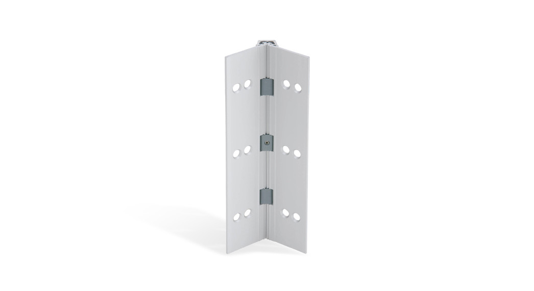
Full Mortise Continuous Hinge withRemovable Electrified Thru-Wire Panel
The XY-Series TWP aluminum hinge is available in standard lengths of 83”, 85”, 95”, and 119” and can be cut to size in the field.
| Model | Description |
| 026XY TWP | Full mortise, concealed narrow frame, with a removable electrified panel |
| 027XY TWP | Full mortise, 2-2Z\v” door, with a removable electrified panel |
| 112XY TWP | Full mortise, with a removable electrified panel |
| 114XY TWP | Full mortise, concealed narrow frame, edge protector, with a removable electrified panel |
| 224XY TWP | Full mortise, edge protector, with a removable electrified panel |
- Please follow the installation instructions carefully. Not doing so may result in improper installation and void the manufacturer’sguarantee. Anodizing or painting the product in the field will void the guarantee.
Installation Notes
Reinforcing and Rivet Nuts:No frame reinforcement is required for doors up to 200 lbs. For doors between 200 and 450 lbs, a 16 gauge channel in the frame is required. For doors greater than 450 lbs (600 lb max.), rivet nuts are required in the frame in addition to the frame reinforcement.
Doors:For doors up to 200 lbs, no door reinforcement is required. For doors, greater than 200 lbs (up to 600 lbs), a 16 gauge channel in the door is required.
Pair of Doors with Mullions:If the mullion is between the doors, treat it as a single door installation. If the mullion is behind the doors, treat as a double door installation.
Determine hinge length.
- All standard hinge lengths are supplied slightly shorter than nominal door height to avoid threshold or carpeting clearance problems. If the hinge is longer than the door and needs to be cut, follow the instructions below. Cut should be made from TOP end only
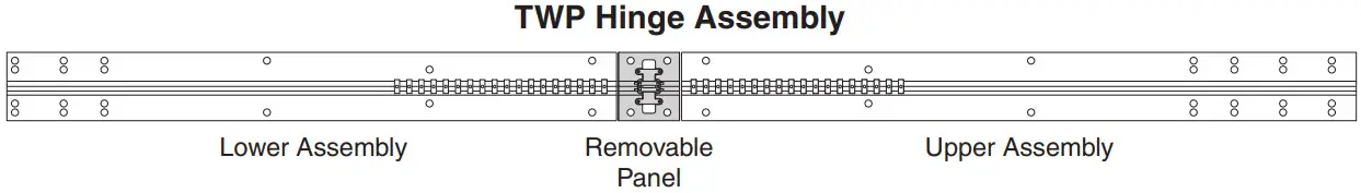
- For reference, the length of the lower assembly is 37Z\x” and the removable panel is 3Z\x”. The length of the upper assembly is determined by the length of the full hinge.
1a If the hinge is taller than the door, the hinge must be cut to match the door height. The hinge must not be taller than the door height. Mark thing with the line where the cut is needed.
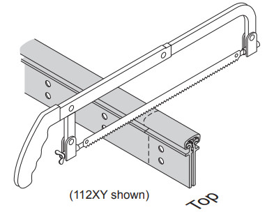
Cut hinge (if necessary).
2a Fold hinge so the channel is up.2b From TOP end only, cut through entirhinge along the line.2c Debur all cut edges with a file.
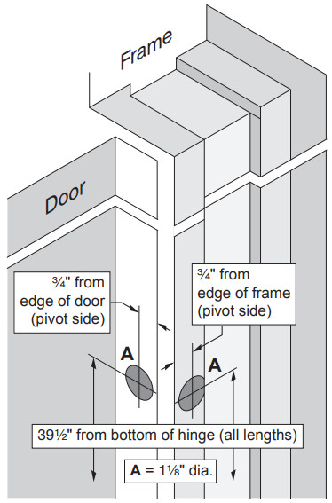
Prepare door and frame for wire access.
3a TWP requires a 1-1/8” diameter hole in the door and frame for wiring.
- Deburr holes to protect wires from abrasion.
Run wiring prior to hanging door.
Mark frame hole location.
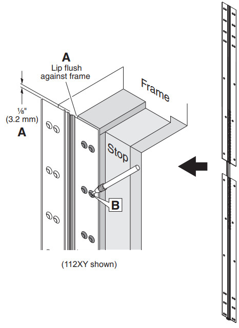
5a Open hinge and place upper/lower TWP hinge assembly flat against the surface of the frame, leaving Z\,” gap between the top of hingand frame header. Hinge assembly should be flush against the edge of the frame from top to bottom.5b Mark center of each hole using a center punch.
- DO NOT attach assemblies to the frame at this time.

Mount TWP hinge assembly to the door.
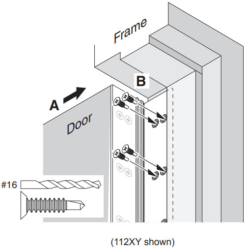
6a Place upper/lower TWP hinge assembly against hinge edge of the door so the top of assembly is flush with the top of door and edge of assembly is flush with the inside face of the door.6b Mark center of each hole with a center punch.6c With assembly held firmly in place, use #12-24 x 3/4” self-drilling tapping screws to fasten the assembly to the door.
- #16 pilot drill is recommended for all holes.
- Fasten top screw first, and bottom-most screw second, making sure hinge is aligned correctly.
6d Install screws into remaining holes.
Mount door to the frame.
7a Move door (with upper/lower TWP hinge assembly attached) into the opening and align mounting holes in frame leaf with marks made in Step 5 above.
- An angle block, jack, or shims will be helpful in positioning the door properly.
7b With hinge and door held firmly in place, use #12-24 x 3/4” self-drilling tapping screws to fasten the TWP hinge assembly to the frame.
- #16 pilot drill is recommended for all holes.
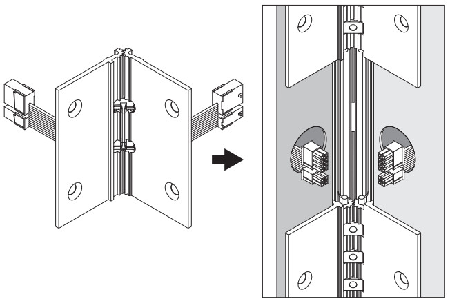
Connect wiring.
8a Open door to 90 degrees or more for access to jamb preps.8b Extract exterior wiring through the prep holes from the door jamb.8c Connect wiring to both sides of the panel using the 8 and 4-pin Molex connectors. If these connectors aren’t on the connecting wires, make terminations as described below.8d Attach wires in accordance with project wiring diagrams.8e Terminate wire connections with appropriate crimp splices or wire nuts.
- It is helpful to stagger terminations. This allows for easier insertion of wires thru the prep hole.
- Warning: Do not hang hinge by wires during installation or serious damage could occur.
8f After all terminations are completed, carefully slide wires through the prepped hole, making sure that wires are placed so they will not be cut or pinched as the hinge is installed.
ELECTRICAL SPECIFICATIONS– Each wire is 24 AWG and rated 50 Volts AC/DC at 3.5 amps (max.) continuous, or 16 amps (max.) pulse.– Maximum pulse width: 400 msec.– Minimum “off” time between pulses: 10 seconds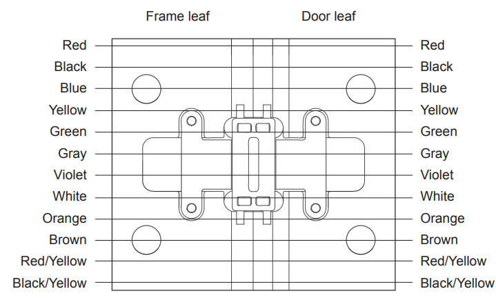
Install XY removable electrified panel.
9a Open upper/lower TWP hinge assembly to 90 degrees or just past.9b Push removable panel into the channel (wire guide fits against channel).9c Position removable panel so it aligns vertically within the opening (1/8” gap above and below).9d Open removable panel to locate the position of the 4 holes.9e Mark the center of each hole using a center punch.9f Use #12-24 x 3/4” self-drilling tapping screws to fasten the thru-wire panel to door and frame.
- #16 pilot drill is recommended for all holes.
Lockdown door position.
![]()
Customer Service
1-877-671-7011www.allegion.com/us
References
[xyz-ips snippet=”download-snippet”]