
Jandy Pro Series Levolor® II Installation and Operation Manual
Electronic Water Leveler
Model K-2100

![]()
WARNING
FOR YOUR SAFETY – This product must be installed and serviced by a contractor who is licensed and qualified in pool equipment by the jurisdiction in which the product will be installed where such state or local requirements exist. The maintainer must be a professional with sufficient experience in pool equipment installation and maintenance so that all of the instructions in this manual can be followed exactly. Before installing this product, read and follow all warning notices and instructions that accompany this product. Failure to follow warning notices and instructions may result in property damage, personal injury, or death. Improper installation and/or operation will void the warranty. Improper installation and/or operation can create unwanted electrical hazard which can cause serious injury, property damage, or death.

ATTENTION INSTALLER – This manual contains important information about the installation, operation and safe use of this product. This information should be given to the owner/operator of this equipment.
Section 1. Safety Information
IMPORTANT SAFETY INSTRUCTIONS PERTAINING TO A RISK OF PROPERTY DAMAGE OR INJURY TO PERSONS
READ AND FOLLOW ALL INSTRUCTIONS
When installing and using this equipment, basic safety precautions should always be observed, including the following:
![]()
WARNING
FOR YOUR SAFETY. This product must be installed and serviced by a professional service technician, qualified in pool/spa installation and maintenance. Improper installation or operation could cause serious injury, property damage, or death. Improper installation or operation will void the warranty.
![]() WARNING
WARNING
Before installing this product, read and follow all warning notices and instructions accompanying it. Failure to follow safety warnings and instructions could result in severe injury, death, or property damage.
![]() WARNING
WARNING
To reduce the risk of injury, do not permit children to use this product unless they are closely supervised at all times.
![]() WARNING
WARNING
Risk of electric shock! Install the control box at least five (5) feet (152.4cm) from the inside wall of the pool and/ or hot tub using non-metallic plumbing. Canadian installations must be at least three (3) meters from the water. Children should not use spas or hot tubs without adult supervision.
Do not use spas or hot tubs unless all suction guards are installed to prevent body and hair entrapment. People using medications and/or having an adverse medical history should consult a physician before using a spa or hot tub.
CAUTION
Sensor wires must be continuous and not spliced. Solder all low voltage wire connections when possible and always use grease-filled wire nuts on low voltage connections.
ATTENTION INSTALLER: Install to provide drainage of compartment for electrical components.
ATTENTION INSTALLER: This manual contains important information about the installation, operation and safe use of this product. This information should be given to the owner/operator of this equipment.
SAVE THESE INSTRUCTIONS
Section 2. System Description
Levolor II by Jandy Model K-2100 is a computer controlled fill device that detects low water conditions.
It can be used in any situation where a consistent liquid level is desired and the low water condition can be detected and acted upon. It is used to fill fountains and to circulate water in cooling towers, ponds, reservoirs, and storage tanks.
The K-2100 kit includes a sensor, remote sensor housing, control box and solenoid valve. For details about the materials in the kit and a list of additional materials needed to install the K-2100, refer to Section 3.1, Materials and Tools.
Sensor
The sensor has three (3) probes: one (1) short probe to measure the minimum operating level of the water, one (1) long probe to measure the low water cutoff level, and one (1) long common probe. The long probes come in 4″, 18″, and 30″ lengths.
The sensor housing is a slip type housing that glues to a 1″ coupling.
NOTE There is an optional threaded-type sensor for a threaded fitting.
Depending on the model, the sensor comes with 50 to 500 feet of wire at the top and three (3) stainless steel contacts at the bottom. The excess wire can be cut off after the installation has been completed.
Control Box
The control box has five (5) LED lights:
- Power On
- Sensor
- Fill
- Low Water Sensor
- Low Water Cutoff
For details about the functions of the LED lights, refer to Section 4.1, Controller Lights.
The control box is factory wired for 220 volt operation, but can optionally be rewired for 110 volt operation. See Section 3.3, Changing Wiring for 110 Volt Operation.
Valve
The K-2100 requires one (1) 24VAC solenoid valve. The Jandy-supplied valve (Part No. SOL100) has a pressure rating that cannot exceed 125 PSI.
2.1 Electrical Specifications
Input:
110VAC, 50/60 HZ, 0.5 AMPS220VAC, 50/60 HZ, 0.5 AMPS
Valve Output: 1 AMP
Relay Output: 1 AMP
CAUTION
Model K-2100 is factory wired for 220VAC service. If the available electrical service is 110VAC, the power supply wiring must be changed to operate on 110VAC, as shown in Figures 3 and 4.
2.2 Schematic
This section contains a schematic for the K-2100.
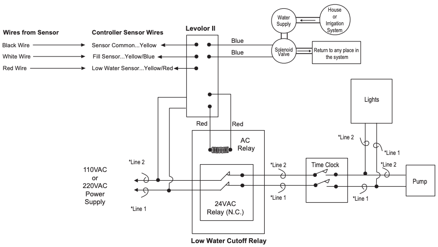
Figure 1. K-2100 Schematic
NOTE Relay contacts must be rated appropriately for line and load voltage/current.
Section 3. Installation Instructions
3.1 Materials and Tools

*The anti-siphon valve is not necessary if the connection is made from the irrigation system.
Open the box and check to see that it contains the contents listed above. If it does not, contact your Jandy dealer or Zodiac Pool Systems, Inc. technical support at 1 (800)-822-7933.
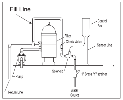
Figure 2. K-2100 Installation
3.2 Installing the Control Box
- Mount the control box to the wall near the pump and filter. See Figure 2. Do not install the control box within 10 feet (3 meters) of the pool edges.
- Mount the control box at eye level. Leave sufficient clearance on all sides of the chassis backplate.
- Check the source voltage. (The unit is factory wired for 220 volt operation.) To modify the wiring for 110 volt operation, see Section 3.3, Changing Wiring for 110 Volt Operation.
- For 220 volt operation, connect the black wire to line 1 and connect the black wire with the yellow stripe to line 2. See Figure 3.

Figure 3. Factory Wiring for 220 Volt Operation
3.3 Changing Wiring for 110 Volt Operation
![]() WARNING
WARNING
Potentially high voltages in the Levolor control box can create dangerous electrical hazards, possibly causing death, serious injury or property damage. Turn off the power at the main circuit breaker providing power to the control box to disconnect the control box from the system. To properly and safely wire the system, be sure to carefully follow the applicable requirements of the National Electrical Code (NEC), NFPA 70 or the Canadian Electrical Code (CEC), CSA C22.1. All applicable local installation codes must also be adhered to.
Refer to Figures 3 and 4 and do the following:
- Cut the splice cap connecting the black/white and the black/red wires. See Figure 3.
- Connect the black/red wire with the black wire and connect to the line side of power. See Figure 4.
- Connect the black/white wire with the black/ yellow wire and connect to the neutral side of power. See Figure 4.
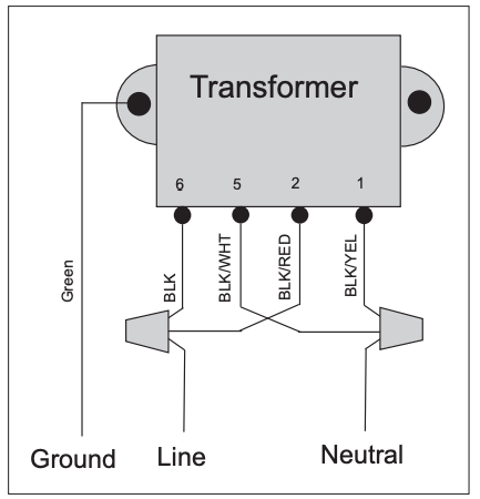
Figure 4. Modified Wiring for 110 Volt Operation
3.4 Grounding
Connect the green ground wire marked ![]() to the grounding terminal of your electrical service or supply panel with a continuous copper conductor having green insulation.
to the grounding terminal of your electrical service or supply panel with a continuous copper conductor having green insulation.
The copper conductor must be equivalent in size to the circuit conductors supplying this equipment, but no smaller than No. 12 AWG (3.3mm).
Refer to your local codes for the acceptable grounding wire gauge.
3.5 Installing the Valve and Relay
NOTE Install the valve with the directional water flow arrow pointing in the appropriate direction. The directional water flow arrow is located on the inlet side of the valve.
A 24VAC solenoid valve will provide water from a supply line to the fountain (or other environment: cooling tower, pond, reservoir, storage tank, etc.).
You can install the supply line either before or after the filter at the equipment pad or on a dedicated line back to the fountain.
Zodiac recommends a minimum 1″ valve and an antisiphon valve, which provides inexpensive insurance against accidental draining of the fountain (or other environment).
Always use an in-line strainer, which can be purchased from Zodiac.
- Connect the 24VAC water solenoid valve to the 18-gauge solid-core burial cable using greasefilled wire nuts.
- Connect the wires from the Fill Valve to the blue wires in the control box using wire nuts. See Figure 7, page 10.
- Connect the wires from the Low Water Cutoff AC Relay Coil to the red wires in the control box using wire nuts. See Figure 7, page 10.
- Turn the flow control knob (+) on the top of the valve (See Figure 5) to set the flow rate to your specifications. (The rate can be set up to 30 GPM.)
- Put the manual ON/OFF lever, located just below the solenoid, in the OFF position, so it can only be opened by the electronic water Levolor. See Figure 6.

Figure 5. Valve Flow Controller

Figure 6. Manual Valve Lever
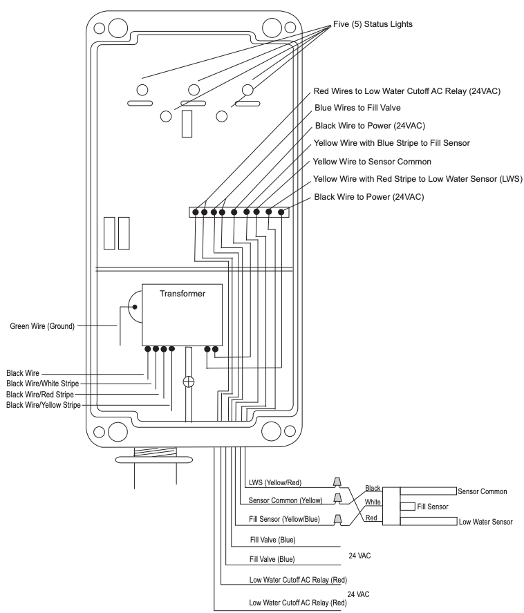
Figure 7. Control Box Wiring
3.6 Installing the Sensor
NOTE Sensor wires must be continuous and not spliced. Solder all low voltage wire connections when possible and always use grease-filled wire nuts on low voltage connections.
NOTE When mounting a slip style sensor in a static pipe, glue 1″ fittings with 793 IPS brand ABS/ PVC glue. Do not glue 2″ fittings.
- Mount the slip sensor vertically in a static pipe. See Figure 8.
- Connect the sensor wires as follows. Refer to Figure 7 and Table 1, shown below.a. Connect the black wire from the long Sensor Common probe to the yellow common wire from the control box using a wire nut.b. Connect the white wire from the short Fill Sensor probe to the yellow wire with the blue stripe from the control box using a wire nut.c. Connect the red wire from the long Low Water Sensor probe to the yellow wire with the red stripe from the control box using a wire nut.
Table 1. Sensor Wire Connections

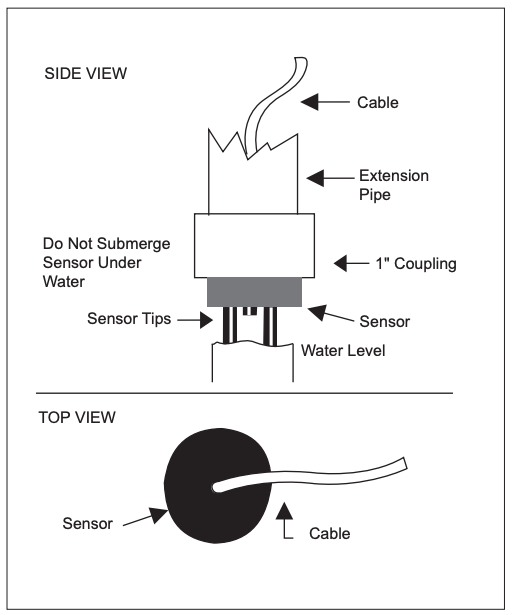
Figure 8. Slip Sensor on Static Pipe
3.7 Static Pipe Installation in a New Fountain
Figure 9 shows a static pipe installation in a new fountain (or other environment: cooling tower, pond, reservoir, storage tank, etc.).
Please note that Zodiac does not supply the Inner Sleeve and Deck Lid Housing Assembly, the Brass Lid, or Drain Cover.
You can construct an Inner Sleeve using a piece of 6″ or 8″ PVC pipe to make a sleeve that fits the lid and collar you are using.
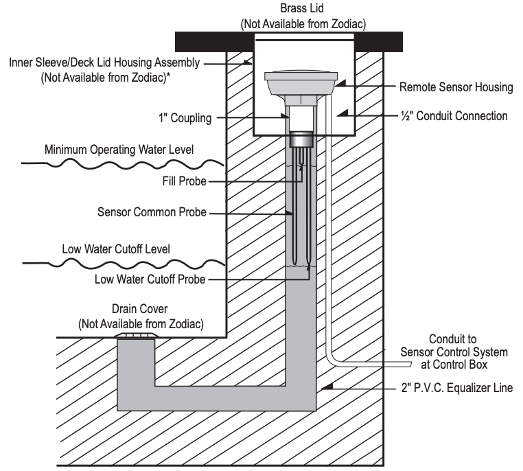
Figure 9. Static Pipe Installation
NOTE When mounting a slip-style sensor in a static pipe, glue 1″ fittings with 793 IPS brand ABS/PVC glue. Do not glue 2″ fittings.
Section 4. Operation
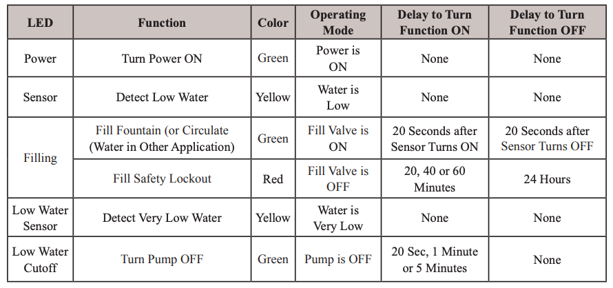
4.1 Controller Lights
The controller has five (5) lights. See Figure 10 and Table 2, LED Indicators.
The Power light turns green when the power is on. The Sensor light turns yellow when water is not touching the Fill Sensor probe.
Then the Fill light turns green, indicating that the valve is operational and filling the fountain (or circulating water in another application). The Fill light turns red when the unit enters Safety Lockout Mode.
The Low Water Sensor light turns yellow when the Low Water Sensor probe is not touching the water. Then the Low Water Cutoff light turns green, indicating that the pump is being shut off.
4.2 Fill Safety Lockout Mode
The Levolor is equipped with a Fill Safety Lockout Mode. This means that if the Fill Sensor probe has not been touched by water within the pre-set Fill time period, the Levolor activates the Safety Lockout, turning the valve off for 24 hours. During Safety Lockout, the Fill light turns from green to red.
The pre-set factory Fill time is 20 minutes. To change it, see Section 4.3, Change Fill Time for Safety Lockout Mode.
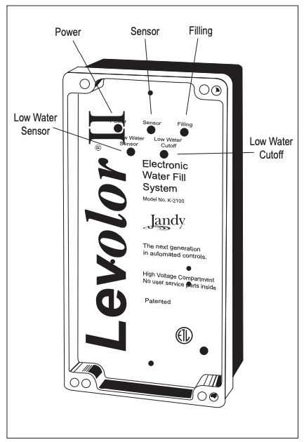
Figure 10. Controller Lights
Table 2. LED Indicators
4.3 Change Fill Time for Safety Lockout Mode
To change the pre-set factory Fill time, turn off the power to the control box, open it up, and cut one or both jumpers on the circuit board.
![]() WARNING
WARNING
Turn off the power to the control box before starting this procedure. Failure to comply may cause a shock hazard, resulting in severe personal injury or death.
- Shut off the power to the control box.
- Take the upper cover plate off the control box by removing the three (3) screws that secure it.
- Locate the jumpers at the top left of the circuit board. See Figure 11.
- Modify the Fill time by cutting Jumpers A and/or B, as shown in Table 3, below.
Table 3. Fill Safety Lockout Mode Settings
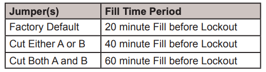
NOTE Cutting the S-1 Jumper will disable the SafetyLockout function.
5. Replace the top cover plate, being careful to align the LED lights with the plastic lenses in the cover.6. Install the three (3) screws. Do not tighten or you will damage the plastic mounts.7. Restore the power to the control box. The new timing changes will take effect.
NOTE If you change the Fill Safety Lockout Mode settings without turning the power off in advance and on afterwards, you will need to cycle the power from OFF to ON for the new timing changes to take effect.

Figure 11. Safety Lockout Jumpers
Section 5. Troubleshooting
Tools required: AC volt meter and No. 6 Phillips screwdriver.
5.1 Observations at Job Site
Make these initial observations when at the jobsite.
- Proper wire usage between the controller and the valve. (Burial style polypropelene-jacketed solid-core wire (at least 18-gauge wire): the same wire as the sensor wire.)
- Proper wire nuts at the valve connection. (Grease-filled wire nuts or gel caps. Conventional wire nuts filled with silicone will not work since some silicones have acids that degrade copper wires.)
- Sensor wire is continuous and not spliced. (No splices between the tips and the controller.)
- Proper use of sensor: slip style for static pipes.
- Proper power input voltage to the box and proper wiring for the voltage (110 or 220 VAC).
- Remove top face plate to verify that control lights on PCB line up with the lens cover.
NOTE Before making changes to connections or settings, reset the controller by powering off for 10 seconds and then powering back on.
5.2 Test Operation of Control Unit
5.2.1 Disconnect Sensor, Valve and Relay
1. Shut power off to the control box.
![]() WARNING
WARNING
Turn off the power to the control box before starting this procedure. Failure to comply may cause a shock hazard, resulting in severe personal injury or death.
CAUTION
Separate wires so they are not touching each other. Failure to comply may cause damage to the control box.
2. Disconnect the sensor from the three (3) sensor wires. Refer to Figure 7, Control Box Wiring, page 10, and Table 1, Sensor Wire Connections, page 11.
a. Disconnect the black wire for the Sensor Common probe from the yellow common wire in the control box.b. Disconnect the white wire for the Fill Sensor probe from the yellow wire with the blue stripe in the control box.c. Disconnect the red wire for the Low Water Sensor probe from the yellow wire with the red stripe in the control box.
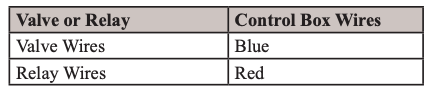
3. Disconnect the valve and the relay from the control box. Refer to Figure 7, Control Box Wiring, page 10, and Table 4, Valve and Relay Connections, shown below.
a. Disconnect the fill valve from the two (2) blue wires in the control box.
NOTE Keep the blue wires separate. Do not let them touch each other.
b. Disconnect the relay from the two (2) red wires in the control box.
Table 4. Valve and Relay Connections
5.2.2 Observe Operation
- Restore power to the control box and observe the operation. The control box is working if steps 2-7 in this section occur.
- The Power light illuminates and turns green.
- The Sensor light illuminates and turns yellow.
- The Low Water Sensor light turns yellow.
- Voltage is sent to the valve and relay.a. After 20 seconds, the Fill light turns green and you can measure 24VAC across the blue wires with an AC volt meter.b. After 20 seconds, the Low Water Cutoff light turns green and you can measure 24VAC across the red wires with an AC volt meter.
- Make sure the sensor probes are touching the water. Then connect the three (3) sensor wires to the sensor. Refer to Table 1, Sensor Wire Connections, page 11.a. Connect the black wire for the Sensor Common probe with the yellow wire in the control box.b. Connect the white wire for the Fill Sensor probe with the yellow/blue wire from the control box. The Fill light will turn off after 20 seconds.c. Connect the red wire for the Low Water Sensor probe to the yellow/red wire from the control box. The Low Water Cutoff light will turn off after 20 seconds.
- Use an AC volt meter to confirm that there is 0 voltage at the blue wires in the control box and 0 voltage at the red wires in the control box.
5.2.3 Manual Valve Override
There is a manual ON/OFF lever on the valve body located just below the solenoid. See Figure 6, Manual Valve Lever, page 9.
If you are having a problem with the system and want to override the electronic water Levolor, you can manually open the valve by putting the lever in the up position ↑ (12 o’clock) for manual filling.
During normal operation, the lever must be in the horizontal position → (3 o’clock) for controlled filling.
5.2.4 Troubleshooting Specific Conditions
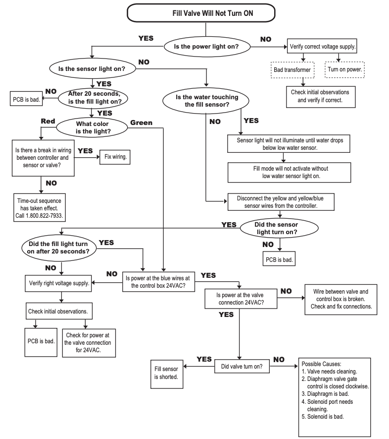
Use the troubleshooting flow charts on the following pages to find and fix these problems:
- Fill Valve Will Not Turn OFF
- Fill Valve Will Not Turn ON
5.3 Fill Valve Will Not Turn OFF

5.4 Fill Valve Will Not Turn ON
Zodiac Pool Systems, Inc.2620 Commerce Way, Vista, CA 920811.800.822.7933 | www.ZodiacPoolSystems.com
©2016 Zodiac Pool Systems, Inc. ZODIAC® is a registered trademark of Zodiac International,S.A.S.U., used under license. All trademarks referenced herein are the property of their respective owners.
References
[xyz-ips snippet=”download-snippet”]