
Jandy® Pro Series Single Element Cartridge Pool Spa CS Filters Installation and Operation Manual
Models:CS100CS150CS200CS250
![]() WARNING
WARNING
FOR YOUR SAFETY – This product must be installed and serviced by a contractor who is licensed and qualified in pool equipment by the jurisdiction in which the product will be installed where such state or local requirements exist. The maintainer must be a professional with sufficient experience in pool equipment installation and maintenance so that all of the instructions in this manual can be followed exactly. Before installing this product, read and follow all warning notices and instructions that accompany this product. Failure to follow warning notices and instructions may result in property damage, personal injury, or death. Improper installation and/or operation will void the warranty.
Improper installation and/or operation can create unwanted electrical hazard which can cause serious injury, property damage, or death.
 ATTENTION INSTALLER – This manual contains important information about the installation, operation and safe use of this product. This information should be given to the owner/operator of this equipment.
Section 1. Important Safety Instructions
READ AND FOLLOW ALL INSTRUCTIONS
1.1 Important Safety Warning
![]()
WARNING
 Do not connect system to an unregulated city water system or other external source of pressurized water producing pressures greater than 35 PSI.
- Pressurized air in system can cause product failure or also cause the filter lid to be blown off which can result in death, serious personal injury, or property damage. Be sure all air is out of system before operating or testing the equipment.
![]() WARNING
WARNING
MAXIMUM OPERATING PRESSURE OF THE FILTER IS 50 PSI. NEVER SUBJECT THE FILTER TO ANY OPERATING PRESSURE EXCEEDING 50 PSI.
 This filter operates under high pressure. When any part of the circulating system, i.e., filter, pump, valve(s), clamp, etc. is serviced, air can enter the system and become pressurized when the system is restarted. Pressurized air can cause product failure or also cause the filter lid to be blown off which can result in death, serious personal injury or property damage. To avoid this potential hazard, follow all of the instructions in this manual.
![]() WARNING
WARNING
To minimize risk of severe injury or death the filter and/or pump should not be subjected to the piping system pressurization test.
Local codes may require the pool piping system to be subjected to a pressure test. These requirements are generally not intended to apply to the pool equipment such as filters or pumps.
Jandy Pro Series pool equipment is pressure tested at the factory.
If however this WARNING cannot be followed and pressure testing of the piping system must include the filter and/or pump BE SURE TO COMPLY WITH THE FOLLOWING SAFETY INSTRUCTIONS:
- Check all clamps, bolts, lids, lock rings and system accessories to ensure they are properly installed and secured before testing.
- RELEASE ALL AIR in the system before testing.
- Water pressure for test must NOT EXCEED 35 PSI.
- Water temperature for test must NOT EXCEED 100°F (38°C).
- Limit test to 24 hours. After test, visually check system to be sure it is ready for operation.
Notice: These parameters apply to Jandy Pro Series equipment only. For non-Jandy equipment, consult equipment manufacturer.
1.2 General Safety Instructions
ATTENTION INSTALLER
This manual contains important information about the installation, operation and safe use of this product. This information should be given to the owner/operator of this equipment.
- Use equipment only in a pool or spa installation.
- Before repositioning valve(s) and before beginning the assembly, disassembly, or adjustment of the clamp, or any other service of the circulating system; (A) turn the pump off and shut off any automatic controls to ensure the system is not inadvertently started during servicing; (B) open the air release valve; (C) wait until all pressure is relieved (air will have stopped flowing from the air release valve).
- Whenever installing the filter clamp follow Section 3.4 of this manual, “Locking Ring/Tank Top Assembly Installation”.
- Once service on the circulation system is complete, follow Section 4 of this manual, “Start-up and Operation”.
- Maintain circulation system properly. Replace worn or damaged parts immediately.
- Be sure that the filter is properly mounted and positioned according to these installation instructions.
- Do not pressure test above 35 PSI. Pressure testing must be done by a trained pool professional.
SAVE THESE INSTRUCTIONS
Section 2. General Information
2.1 Introduction
This manual contains information for the proper installation and operation of the Jandy Pro Series CS Cartridge Filters. Procedures in this manual must be followed exactly. For technical assistance, contact our Technical Support Department at 1.800.822.7933.
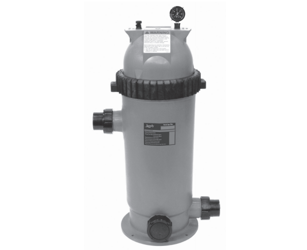
2.2 Description
Cartridge filters do not require sand or diatomaceous earth as the filter medium. Instead they contain a filter cartridge element which is easily removed for cleaning or replacement.
Dirty water flows into the filter tank and is directed through the filter cartridge. The debris is collected on the surface of the cartridge as the water flows through it. The water will travel through the central filter core towards the bottom of the filter into the lower manifold. Clean water is returned to the swimming pool through the filter outlet port at the tank’s bottom.
As debris collects in the filter, the pressure will rise and water flow to the pool will diminish. The filter cartridge must be cleaned when the operating pressure of the filter rises 10 psi from the operating pressure of a clean cartridge. See Section 6 “Cleaning the Filter”.
NOTE A filter removes dirt and other suspended particles but does not sanitize the pool. Pool water must be sanitized and chemically balanced for clear water. The filtration system should be designed to meet local health codes. At a minimum, the system should turnover the total volume of water in your pool two (2) to four (4) times in a 24 hour period.
2.3 General Requirements
- For best overall performance place the system as close to the pool as possible.
- The filter should be located on a level concrete slab so that the orientation of the valve outlets and the pressure gauge are convenient and accessible for the installation and operation of the unit.
- Protect the filter from the weather.
- If fitting a chlorinator and/or any other device into the filtration plumbing circuit, great care must be exercised to ensure that the appliance is installed in accordance with the Manufacturer’s Instructions and any applicable standards that may exist.
- Use Jandy Pro Series universal unions to connect each component of the water conditioning system for future servicing. All Jandy Pro Series filters come with these type of fittings.WARNINGThe maximum operating pressure for this filter is 50 psi. Never subject the filter to operating pressure exceeding 50 psi. Operating pressures above 50 psi can cause product failure or also cause the lid to be blown off, which can result in death, serious personal injury, or property damage.
- When performing hydrostatic pressure tests or when testing for external leaks of the completed filtration and plumbing system, ensure that the maximum pressure the filtration system is subjected to does not exceed the maximum working pressure of any of the components within the system.
Section 3. Installation Instructions
![]() WARNING
WARNING
Use equipment only in a pool or spa installation. Do not connect system to an unregulated city water system or other external source of pressurized water producing pressures greater than 35 psi.
3.1 Filter Location
![]() WARNING
WARNING
To Reduce the Risk of Fire, install pool equipment in an area where leaves or other debris will not collect on or around the equipment. Keep surrounding area clear of all debris such as paper, leaves, pine-needles and other combustible materials.
- Select a well-drained area, one that does not flood when it rains. Damp, non-ventilated areas should be avoided.
- The filter should be installed on a firm, solid, and level surface or platform to avoid risk of settlement. Do not use sand to level the filter as the sand will wash away; filter systems can weight up to 300pounds. Check local building codes for additional requirements. (Ex. Equipment pads in Florida must concrete and equipment must be secured to the pad.)
- Install electrical controls at least five (5) feet from the filter. This will allow enough room to stand away from the filter during start-up.
- Allow sufficient clearance around the filter to permit a visual inspection of the clamp ring. See Fig. 1.Figure 1. Filter Location – Top ViewWARNINGWater discharged from an improperly positioned filter or valve can create an electrical hazard which can cause death, serious injury or property damage.CAUTIONMaintain your pressure gauge in good working order. The pressure gauge is the primary indicator of how the filter is operating.
- Allow sufficient space above the filter to remove the filter lid and filter element for cleaning and servicing.
- Position the filter to safely direct water drainage. Align the air release valve to safely direct purged air or water.
- If the filter is to be installed below the water level of the pool, isolation valves should be installed on both the suction and return lines to prevent back flow of pool water during any routine servicing that may be required.
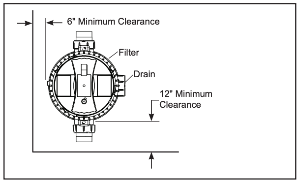 Figure 1. Filter Location – Top View
3.2 Filter Preparation
- Check carton for damage due to rough handling in shipment. If carton or any filter components are damaged, notify carrier immediately.
- Carefully remove the accessory package. Remove the filter tank from the carton.
- A visual inspection of all parts should be made now. See parts list in Section 9.
- Install the pressure gauge and adapter assembly to the threaded hole marked “Pressure Gauge” at the top of the filter See Fig. 2.
- Install the air release valve into the threaded opening marked “Air Release” at the top of the filter. See Fig. 2.NOTE Teflon tape is included in the accessory bag.Figure 2. Pressure Gauge and Pressure Release Assembly
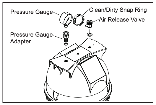 Figure 2. Pressure Gauge and Pressure Release Assembly
3.3 Filter Installation
![]() WARNING
WARNING
To avoid an electrical shock hazard, which can result in serious injury or death, ensure that all electrical power to the system is turned off before approaching, inspecting or troubleshooting any leaking valves or plumbing that may have caused other electrical devices in the surrounding area to get wet.
- This filter operates under pressure. When the locking ring is properly seated and the filter is operated without air in the water system, this filter will operate in a safe manner.
- If the system can be subjected to higher pressures than the maximum working pressure of the lowest rated component, install an ASME® approved automatic Pressure Relief Valve or Pressure Regulator in the circulation system.
- Place the filter on the concrete pad, lined up with the inlet and outlet pipes.
- To reduce pressure losses, 2″ (minimum) piping is recommended for plumbing the system. Never exceed the manufacturer’s maximum recommended filter flow rates.
- For best efficiency use the fewest possible number of fittings. This will prevent a restriction of the water flow.
- Make all plumbing connections in accordance with local plumbing and building codes. Filter unions are provided with an o-ring seal. Use silicone based lubricants on the o-rings to avoid damage. Do not use pipe joint compound, glue or solvent on union threads.
- Keep piping tight and free of leaks. Pump suction line leaks may cause air to be entrapped in filter tank or loss of prime at the pump. Pump discharge line leaks may show up as equipment pad leaks or air being discharged through the return lines.Figure 3. Basic Pool/Spa Combination Plumbing
- Support the inlet/outlet pipes independently to prevent any undue strains.
- Place the union nuts over the pipes and clean both the pipes and union tailpieces with an appropriate NSF® approved All Purpose cleaner/primer. Glue the pipes to the tailpieces using an appropriate All Purpose NSF approved adhesive/glue.NOTE: Zodiac recommends Weld-On 724 PVC to CPVC Cement to glue Schedule 40 PVC.
- Drill pilot holes into the equipment pad with a ¼” masonry bit. Use the holes in the tank bottom base as a guide.
- Install ¼ x 2¼” Stainless Steel Tapcon® screws and tighten.
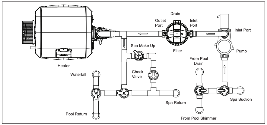 Figure 3. Basic Pool/Spa Combination Plumbing
3.4 Locking Ring/Tank Top Assembly Installation
![]() WARNING
WARNING
Follow these instructions carefully. Improper locking ring installation can cause product failure or also cause the filter lid to be blown off which can result in death, serious personal injury or property damage.
- Be certain the o-ring is in position in the upper tank half. Press the filter lid over the lower half until seated. Lubricating the o-ring with a silicone based lubricant will help with installation. See Fig. 4.
- Put the locking ring/tank top assembly on the lower housing and thread it onto the filter. Turn the locking ring clockwise until you hear it snap over the tabs on the lower half of the tank.Figure 4. Locking Ring
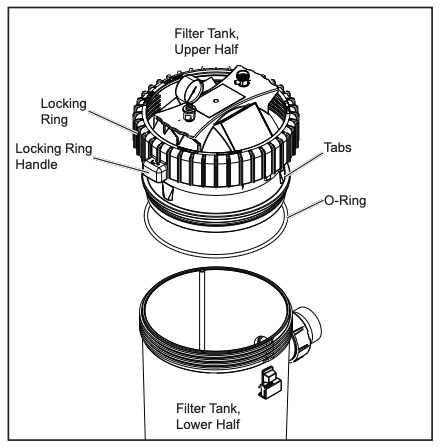 Figure 4. Locking Ring
![]() WARNING
WARNING
This filter operates under high pressure. Ensure that the locking ring is turned until it clicks past the stop tab. Failure to properly install the locking ring or using a locking ring that is damaged can cause product failure or also cause lid separation, which could result in death, serious personal injury or property damage. To avoid injury, keep fingers clear of the lower tank threads and stop tab.
Section 4. Start-Up and Operation
![]()
WARNING
NEVER start pump while standing within five (5) feet of the filter. Starting the pump while there is pressurized air in the system can cause product failure or also cause the filter lid to be blown off, which can cause death, serious personal injury or property damage.
![]() WARNING
WARNING
NEVER operate the filter system at more than 50 psi of pressure. Operating the filter system in excess of 50 psi can cause product failure or also cause the filter lid to be blown off, which can cause death, serious personal injury or property damage.
CAUTION
DO NOT operate filter at water temperatures above 105° F (40.6° C). Water temperatures above the manufacturer’s recommendations will shorten the life span of the filter and void the warranty.
4.1 New Pool and Seasonal Start-up
- Turn off the filter pump and switch off the circuit breaker to the pump motor.
- Check that the filter drain cap and nut are in place and tight.
- Check that the tank locking ring is properly seated and tight.
- Open the pump hair/lint pot lid and fill the pump basket with water to prime the system. Replace the pump lid. You may have to do this a few times on new and seasonal start ups.
- Open the air release valve on top of the filter (do not remove the valve).
- Be sure to open any isolation valves that were installed in the system.
- Stand clear of the filter and start the pump to circulate water through the system. When all the air is bled from the system and a steady stream of water starts to come out of the air release valve, close the valve.
- Watch the pressure gauge to be sure that the pressure does not exceed 50 psi. If the pressure approaches 50 psi, immediately turn the pump off and clean the filter cartridges. If the pressure remains high after cleaning the filter, refer to the troubleshooting guide, Section 8, for possible causes and solutions.
- After the pressure gauge has stabilized, turn the bezel ring so that the arrow next to the word “CLEAN” aligns with the needle of the gauge. See Figure 5. As the filter cleans the water, and the cartridges begin to clog the pressure begins to increase. When the needle of the pressure gauge aligns with the arrow next to the word “DIRTY” on the bezel, it is time to clean the filter, see Section 6.3. This indicates an increased pressure of between 10 and 12 psi above original starting pressure.Figure 5. Pressure Gauge with Clean/Dirty Snap Ring
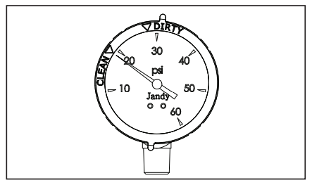 Figure 5. Pressure Gauge with Clean/Dirty Snap Ring
Section 5. Filter Disassembly and Assembly
![]() WARNING
WARNING
NEVER attempt to assemble, disassemble or adjust the filter when there is pressurized air in the system. Starting the pump while there is any pressurized air in the system can cause product failure or also cause the filter lid to be blown off, which can cause death, serious personal injury or property damage.
5.1 Filter Element Removal
- Turn off the filter pump and switch off the circuit breaker to the pump motor.
- Open air release valve on top of the filter tank to release all pressure from inside the tank and system, see Fig. 6. Close any filter isolation valves on the system to prevent flooding.
- Open the filter tank drain. When the filter tank has drained, close the drain.
- Remove the locking ring/tank top assembly by pushing on the locking tab and turning the lock ring counterclockwise.
- Remove the top of the filter. Inspect the tank o-ring for damage. Clean or replace the o-ring as necessary.
- Remove the filter element from the tank bottom and clean or replace as necessary.
- Place the new or cleaned filter element into the tank bottom.
- Use a silicone based lubricant on the new or cleaned o-ring and place the o-ring onto the tank top.
- Place the tank top onto the tank bottom. Be sure the tank halves are seated properly.
- Tighten the locking ring, see Section 3.4, “Locking Ring/Tank Top Assembly Installation”.
- Follow steps 5 thru 8 under Section 4.1, “New Pool and Seasonal Start-Up”.
![]() WARNING
WARNING
If the breather tube is not fully seated or is damaged or clogged, trapped air can cause product failure or also cause the filter lid to be blown off which can result in death, serious personal injury or property damage.
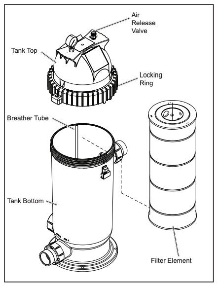
Figure 6. Filter Element Removal
Section 6. Maintenance
6.1 General Maintenance
- Wash outside of filter with water or TSP (trisodium phosphate) with water. Rinse off with a hose. Do not use solvents or detergents to clean the filter, solvents will damage the plastic components of the filter.
- Check pressure during operation at least once a week.
- Remove any debris from the skimmer basket and hair/lint pot on pump.
- Check pump and filter for any leaks. If any leaks develop, turn off the pump and call a qualified pool service technician.
- Product safety signs or labels should be periodically inspected and cleaned by the product user as necessary to maintain good legibility for safe viewing.
- Product safety signs or labels should be replaced by the product user when a person with normal vision, including corrected vision, is no longer able to read the safety signs or label message panel text at a safe viewing distance from the hazard. In cases where the product has an extensive expected life or is exposed to extreme conditions, the product user should contact either the product manufacturer or other appropriate source to determine means for obtaining replacement signs or labels.
- Installation of new replacement safety signs or labels should be in accordance with the sign or label manufacturer’s recommended procedure.
6.2 Pressure Gauge
CAUTION
Maintain your pressure gauge in good working order. The pressure gauge is the primary indicator of how the filter is operating.
- During operation of the filtration system, check the pressure gauge/air release assembly for air or water leaks at least once a week.
- Keep the pressure gauge in good working order. If you suspect a problem with the gauge, Zodiac Pool Systems LLC recommends you call a service technician to do any work on the filter/pump system.
6.3 Cleaning the Filter Cartridge
- Turn off the filter pump and switch off the circuit breaker to the pump motor.
- If the filter is installed below pool level, close any filter isolation valves to prevent flooding.
- Open the air release valve on top of the filter and wait for all air pressure to be released.
- Open the filter tank drain. When the filter tank has drained, close the drain. Place it upright in a area suitable for washing.
- Open filter tank and remove cartridge element, see Section 5.1 “Filter Element Removal”. Place it upright in an area suitable for washing.
- Use a garden hose and nozzle to wash each pleat of the element.NOTE Algae, suntan oil, calcium and body oils can form coatings on filter element which may not be removed by normal hosing. To remove such materials, soak the element in de-greaser and then a de-scaler. Your local pool shop will be able to recommend suitable products.
- Replace the cartridge back into the filter tank. Inspect the o-ring for cracks or wear marks. Place the o-ring back onto the filter tank top. Replace the top of the tank. See Section 3.4 “Locking Ring/Tank Top Assembly Installation”.
- Reopen the isolation valves if they were closed.
- Stand clear of the filter, start the pump and circulate the water until water sprays out of the air release valve. Close the air release valve. The filter is now back in operating mode.
- Watch the pressure gauge to be sure that the pressure does not exceed 50 psi. If the pressure approaches 50 psi, immediately turn the pump off and clean the filter cartridges. If the pressure remains high after cleaning the filter, refer to the troubleshooting guide, Section 8, for possible causes and solutions.
6.4 Breather Tube Maintenance
- Turn off the filter pump and switch off the circuit breaker to the pump motor.
- If the filter is installed below pool level, close any filter isolation valves to prevent flooding.
- Open the air release valve on top of the filter and wait for all air pressure to be released.
- Loosen the drain plug at the base of the filter to ensure the tank is empty.
- Open the filter tank.
- Check breather tube for obstructions or debris. If necessary, remove the breather tube and flush with running water until the obstruction or debris is cleared. See Figure 7.
- If the obstruction or debris can not be removed or the breather tube is damaged, STOP using the filter immediately and replace the breather tube assembly.WARNING If the breather tube is not fully seated or is damaged or clogged, trapped air can cause product failure or also cause the filter lid to be blown off which can result in death, serious personal injury or property damage.
- Reassemble breather tube. Fully seat the breather tube into the bottom tank.
- Replace the filter locking ring/tank top assembly on the filter and tighten. See Section 3.4 “Locking Ring/Tank Top Assembly Installation”.
- Reopen isolation valve if they were closed.
- Stand clear of the filter, start the pump and circulate the water until water sprays out of the air release valve. Close the air release valve. The filter is now back in operating mode.
- Watch the pressure gauge to be sure that the pressure does not exceed 50 psi. If the pressure approaches 50 psi, immediately turn the pump off and clean the filter cartridges. If the pressure remains high after cleaning the filter, refer to the troubleshooting guide, Section 8, for possible causes and solutions.
Section 7. Winterizing
- Turn off the filter pump and switch off the circuit breaker to the pump motor.
- Open air release valve on top of the filter. Do not remove.
- Loosen the drain nut and cap at the base of the filter to ensure that the tank is empty.
- Drain circulation system of all water. 5. Cover the system with a tarpaulin or plastic sheet to protect it from the weather.
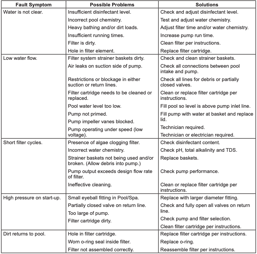
Section 8. Troubleshooting
- For a list of common problems and solutions see the Troubleshooting Guide below.
- Zodiac recommends that you call a qualified service technician to do any work on the filter/pump system. For technical assistance, contact our Technical Support Department at 1.800.822.7933.
Table 2. Troubleshooting Guide
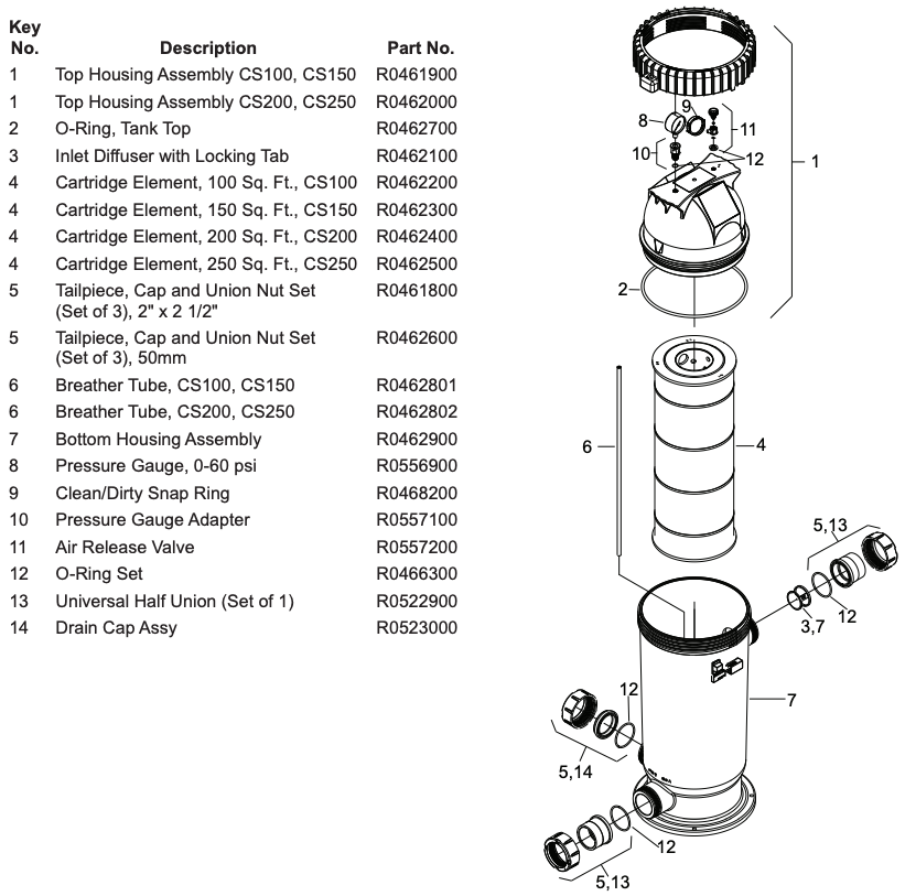
Section 9. Parts List and Exploded View
9.1 Jandy Cartridge Filter, CS Series
9.2 Jandy CS Cartridge Filter Exploded View
Section 10. Performance and Specifications
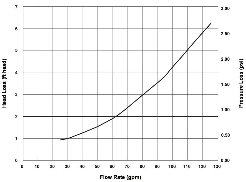
10.1 Headloss Curve, CS Series
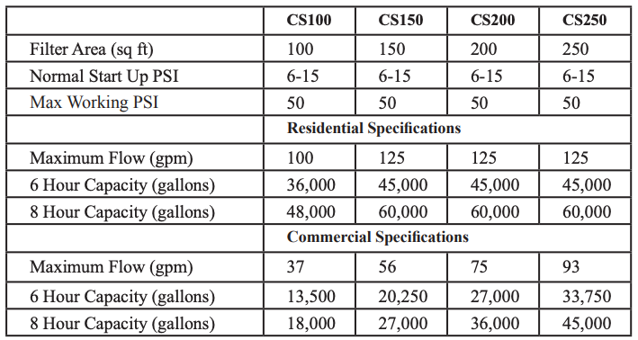
10.2 Performance Specifications
10.3 Dimensions
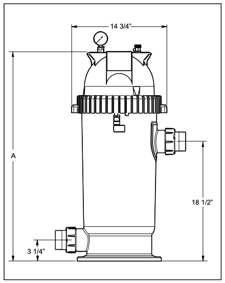
Figure 7. Dimensions, CS Cartridge Series Filter
Dimension “A”:
- CS100 – 32 ⅜”
- CS150 – 32 ⅜”
- CS200 – 42 ½”
- CS250 – 42 ½”
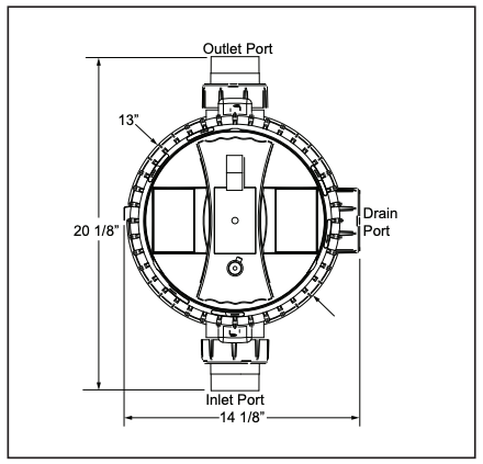
Figure 8. Dimensions, CS Cartridge Series Filter – Top View
References
[xyz-ips snippet=”download-snippet”]