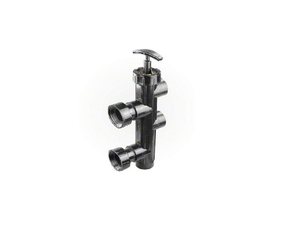
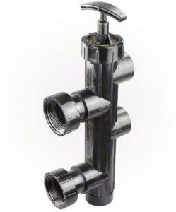
Jandy R0442200 Slide Valve Replacement Kits
|
FOR YOUR SAFETY: This product must be installed and serviced by a professional pool/spa service technician.The procedures in this instruction sheet must be followed exactly. Ensure that all electrical power to the system is turned off before approaching, inspecting or troubleshooting any leaking valves that may have caused other electrical devices in the surrounding area to get wet. Failure to do so could result in an electrical hazard which could result in death or serious injury due to electrical shock, and may also cause damage to property and/or operation that may void the warranty. |
These instructions are to be used with the following Jandy Replacement Kits:R0442200– Slide Valve Shaft Assembly Replacement KitR0473000– Slide Valve Rebuild Kit (O-ring, Roll Pin, and Index Plate/Lid (BWVL-SLD)R0442100 — Slide Valve O-rings and Pins Replacement Kit (SVLV8)
This document gives instructions for replacing the o-rings, roll pins, index plate/lid, and shaft assembly on the Jandy Slide Valve. These instructions must be followed exactly. Read through the instructions completely before starting the procedure. Please save these instructions.
To identify the parts that are included in your kit(s), refer to the parts list and exploded view located on page 4 of this manual. If any parts are missing from the kit(s) please call your local Jandy distributor for assistance. For technical assistance please contact our Technical Support Department at (800) 822-7933
|
To prevent equipment damage and possible injury, the pump must be turned off and the pressure relief valve on top of the filter must be opened. Wait for all air to evacuate the system |
Section 1. Remove Existing Slide Valve Lid Union Nut, Lid O-ring, and Shaft Assembly
- Turn off power to the system. Release all pressure from the system at the filter and drain the filter. Position system valves to isolate the slide valve.
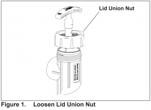
- Loosen the existing lid union nut on the slide valve (see Figure 1).

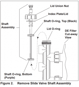
- Grab the existing slide valve handle and pull the shaft assembly out of the valve (see Figure 2).
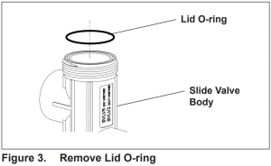
- Remove the existing lid o-ring (see Figure 3).
- Inspect the sealing surface on the index plate/lid and ensure that it is clean and free of debris.
Section 2. Remove Shaft O-rings, Roll Pins, and Index Plate/Lid
NOTE Perform only if installing replacement kit R0473000.
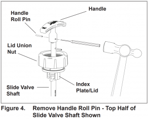
- Using a punch and a ball peen hammer, tap the existing roll pin out of the slide valve handle (see Figure 4). Remove the handle
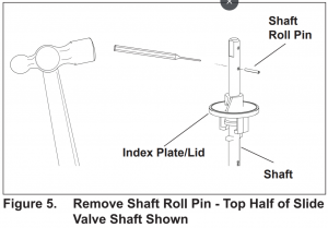
- Using a punch and ball peen hammer, tap the existing roll pin out of the slide valve shaft (see Figure 5).
- Slide the existing index plate/lid off the slide valve shaft.
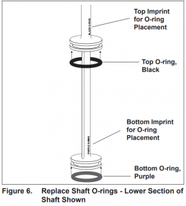
- Remove existing shaft o-rings. The top o-ring is black and the bottom o-ring is purple.NOTE The o-ring color locators are imprinted in the slide valve shaft.
- Wash the shaft with clean water and dry with a lint-free cloth. Ensure that all debris is removed.
Section 3. Install New Shaft O-rings, Roll Pins, and Index Plate/Lid
NOTE: Be aware that the roll pins are different lengths; the handle roll pin is 1″ long and the shaft roll pin is 13/16″ long.
- Remove the new shaft o-rings from the packaging and lubricate with 100% silicone grease lubricant. Do not use any lubricant containing petroleum products.
- Place the o-rings in the groves on the stem of the shaft (see Figure 6). Ensure that the o-rings are properly seated.
CAUTION
The o-rings must be installed in the correct location. Ensure that the black o-ring is installed on the top seating surface of the shaft, and the purple o-ring is installed on the bottom seating surface. The o-ring color locators are imprinted in the slide valve shaft.
- Remove the new index plate/lid from the packaging and slide onto the slide valve shaft. Refer to Figure 5 for the correct orientation of the index plate/lid.
- Remove one (1) new roll pin from the packaging. The replacement kit comes with two (2) roll pins, one is to be used to secure the handle.
- Place the new roll pin into the hole provided in the shaft above the index plate/lid. Using a ball peen hammer, tap the roll pin into the hole until the start end of the pin is flush with the shaft. The remaining section of the roll pin will protrude out of the shaft.
- Place the handle removed in Section 2, Step 1 on the slide valve shaft.NOTE The handle and slide valve shaft are keyed; therefore the handle will fit only one way on the shaft.
- Ensure that the holes on the shaft and handle line up correctly.
- Remove the remaining roll pin from the packing. Using a punch and ball peen hammer, tap the roll pin into the hole of the handle and shaft. Ensure that the roll pin is inserted (tapped in) so that it is flush with the handle surface.
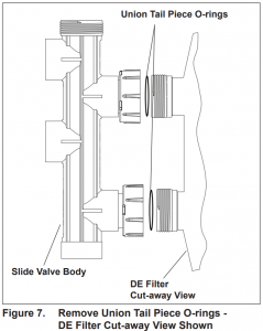
Section 4. Remove Tail Piece O-rings
- Loosen the union coupling nuts that secure the slide valve body to the filter (see Figure 7). Pull the slide valve body away from the filter to break the connection.
- Remove the existing o-rings from the union tail pieces (see Figure 7).
Section 5. Replace Tail Piece O-rings
- Wash the union connections with clean water and dry with a lint-free cloth. Ensure that all debris is removed.
- Lubricate the o-rings with 100% silicone grease lubricant. Do not use any lubricant containing petroleum products.
- Place the o-rings in the groves provided on the union tail pieces (see Figure 8). Ensure that the o-rings are properly seated.
- Position the slide valve body back onto the filter and tighten the union nuts.
Section 6. Install New Slide Valve Lid Union Nut, Lid O-ring, and Shaft Assembly
- Remove the new lid o-ring from the packaging and lubricate with 100% silicone grease lubricant. Do not use any lubricant containing petroleum products.
- Place the new lid o-ring in the lid placement grove on the top of the slide valve.
- Remove the new slide valve shaft assembly from the packaging. Lubricate the shaft o-rings with 100% silicone grease lubricant. Do not use any lubricant containing petroleum products.
- Place the new slide valve shaft assembly into the slide valve body. Ensure that the index plate/lid is completely seated on the valve body. NOTE The index plate/lid is keyed to prevent rotation in the valve body.
- Tighten the lid union nut.
- Place the Slide Valve in the operating position for filtration mode. (Jandy DE Filters and JS series Filters) Ensure that the Slide Valve handle is fully depressed (handle and piston pushed all the way down). Turn the handle until the stainless steel pin on the piston locks into the index plate/lid. (Sand Filters of a manufacturer other than Jandy with the inlet port being the top port) Ensure that the Slide Valve handle is fully extended (handle pulled all the way up).
- Restore power to the system and check the valve for proper operation.
|
CAUTION To avoid costly equipment damage, after verifying proper water flow and prior to putting system into normal operating conditions, flush the system using Backwash mode until the waste water is clean. Refer to Section 4 in the Jandy Slide Valve Installation and Operation Manual for Backwash mode operation instructions. |
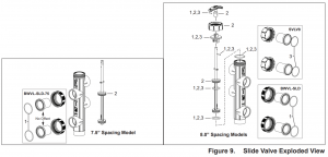
Section 7. Replacement Kit Parts List
| Key No. | Description | Qty. | Order Part No. |
| 1 | Rebuild Kit (O-rings, Roll Pins, and Index Plate/Lid) (BWVL-SLD) | 1 | R0473000 |
| O-ring, Lid | 1 | ||
| O-ring, Shaft, Top, Black | 1 | ||
| O-ring, Shaft, Bottom, Purple | 2 | ||
| O-ring, Union Tail Piece | 1 | ||
| Roll Pin, Handle (1″) | 1 | ||
| Roll Pin, Shaft (13/16“) Index Plate/Lid | 1 | ||
| 2 | Shaft Replacement Kit | R0442200 | |
| Shaft, 8.0″ Spacing | 1 | ||
| Shaft, 7.5″ Spacing | 1 | ||
| Handle | 1 | ||
| Roll Pin, Handle (1″) | 1 | ||
| Roll Pin, Shaft (13/16″) | 1 | ||
| Index Plate/Lid | 1 | ||
| Lid Union Nut | 1 | ||
| O-ring, Lid | 1 | ||
| O-ring, Shaft, Top, Black | 1 | ||
| O-ring, Shaft, Bottom, Purple | 1 | ||
| 3 | O-rings and Pins | R0442100 | |
| Replacement Kit (SVLV8) | 1 | ||
| Roll Pin, Handle (1″) | 1 | ||
| Roll Pin, Shaft (13/16″) | 1 | ||
| Index Plate | 1 | ||
| O-ring, Shaft, Top, Black | 1 | ||
| O-ring, Shaft, Bottom, Purple | 1 | ||
| O-ring, Union Tail Piece | 3 |
Zodiac Pool Systems LLC2882 Whiptail Loop # 100, Carlsbad, CA 92010USA | Jandy.com | 1.800.822.7933
©2021 Zodiac Pool Systems LLC. All rights reserved. ZODIAC® is a registered trademark of Zodiac International, S.A.S.U. used under license. All other trademarks are the property of their respective owners.

References
[xyz-ips snippet=”download-snippet”]