![]()
INSTALLATION AND OPERATION MANUAL
![]()
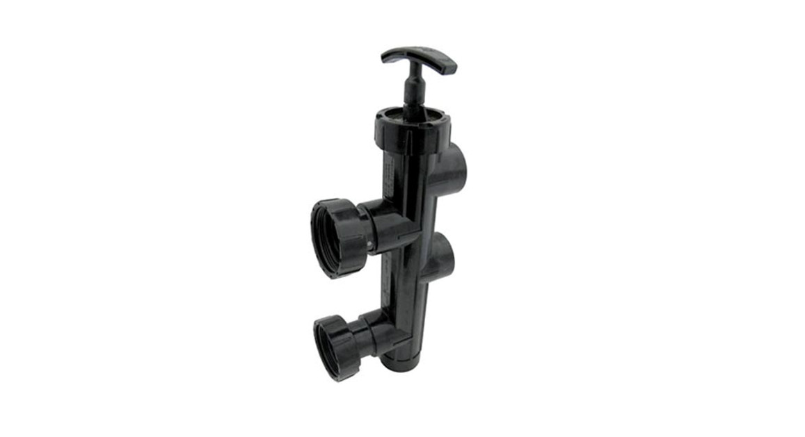
JandySlide Valve and Backwash Valve
 WARNINGFOR YOUR SAFETY – This product must be installed and serviced by a contractor who is licensed and qualified in pool equipment by the jurisdiction in which the product will be installed where such state or local requirements exist. The maintainer must be a professional with sufficient experience in pool equipment installation and maintenance so that all of the instructions in this manual can be followed exactly. Improper installation and/or operation can create dangerous high pressure which can cause a catastrophic product failure and/or cause the filter lid to be blown off possibly causing death, serious injury or property damage. Before installing this product, read and follow all warning notices and instructions that accompany this product. Failure to follow warning notices and instructions may result in death, serious injury or property damage. Consult Zodiac customer service at 1-800-822-7933 for assistance. Improper installation and/or operation may void the warranty.
Section 1. Safety Information
WARNINGFOR YOUR SAFETY: This product must be installed and serviced by a professional pool/spa service technician. The procedures in this instruction sheet must be followed exactly. Improper installation and/or operation may void the warranty. WARNINGEnsure that all electrical power to the system is turned off before approaching, inspecting or troubleshooting any leaking valves that may have caused other electrical devices in the surrounding area to get wet. Failure to do so could result in an electrical hazard that could result in death or serious injury due to electrical shock, and may also cause damage to property. WARNING

- Do not connect the system to an unregulated city water system or another external source of pressurized water producing pressures greater than 35 PSI.
- Pressurized air in the system can cause product failure or also cause the filter lid to be blown off which can result in death, serious personal injury, or property damage. Be sure all air is out of the system before operating or testing the equipment.
WARNINGTo minimize the risk of severe injury or death the filter and/or pump should not be subjected to the piping system pressurization test. Local codes may require the pool piping system to be subjected to a pressure test. These requirements are generally not intended to apply to the pool equipment such as filters or pumps. Jandy pool equipment is pressure tested at the factory. If however this WARNING cannot be followed and pressure testing of the piping system must include the filter and/or pump BE SURE TO COMPLY WITH THE FOLLOWING SAFETY INSTRUCTIONS:
- Check all clamps, bolts, lids, lock rings, and system accessories to ensure they are properly installed and secured before testing.
- RELEASE ALL AIR in the system before testing.
- AIR PRESSURE MUST NOT be used for pressure testing.
- Water pressure for the test must NOT EXCEED 35 PSI.
- Water temperature for the test must NOT EXCEED 100°F (38°C).
- Limit test to 24 hours. After the test, visually check the system to be sure it is ready for operation.
Notice: These parameters apply to Jandy equipment only. For non-Jandy equipment, consult the equipment manufacturer.
CAUTIONNever run the pump without water. Running the pump “dry” for any length of time can cause severe damage to both the pump and motor and may void the warranty.
WARNINGTo avoid the risk of damage or injury, verify that all power is turned off before starting this procedure.
READ AND FOLLOW ALL INSTRUCTIONS
Section 2. BWVL-SLD-75 with SFSM
Series Filter Installation
The following manual provides instructions for installing the Jandy slide valve BWVL-SLD-75 onto the Jandy SFSM Series filter. The instructions must be followed exactly. Read through the instructions completely before starting the procedure. Please save these instructions. The slide valve is a two-position valve. The valve handle must be fully extended or fully depressed. This valve can not be throttled.
a. Installation
WARNINGEnsure that all electrical power to the system is turned off before approaching, inspecting or troubleshooting any leaking valves that may have caused other electrical devices in the surrounding area to get wet.
- Remove the slide valve from the packaging. Twist the handle on the slide valve several times to verify that the piston moves freely. If any of the components show signs of damage pleasecall Zodiac at 1-800-822-7933.
- Turn off all power to the system.• For new installations steps “3” through “6” may be skipped. Proceed to step 7.
- Open the pressure relief valve on top of the filter. Wait for all air to evacuate the system.
- If the filter is installed below pool level, close the suction and return line valves to isolate the filtration system or ensure that proper isolation check valves are in place.
- Drain the water from the filter. Please follow the filter manufacturers draining instructions and ensure that wastewater is disposed of properly.
- Remove the existing valve from the filter.
- Remove the two o-rings from the packaging.
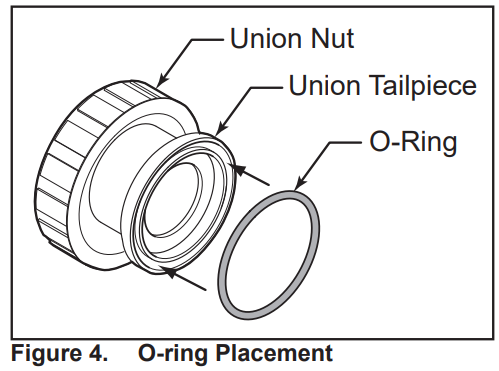
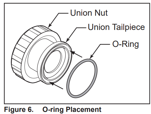
- Place the o-rings on the face of the union tailpieces, where the face of the union will connect to the filter ports, see Figure 1.
 • Make sure each o-ring is properly seated into the groove of each union tailpiece.• The slide valve has molded labels on each port.• The ports are equipped with union connections that match the connections on the filter ports.• DO NOT USE liquid thread sealant on any threaded plastic connection.
 - Hold the slide valve upright and place it onto the filter ports. See Figure 2.
- Tighten both union nuts to secure the valve on the filter.
- Follow filter manufacturers’ instructions for filter placement on the equipment pad.
- Plumb the discharge of the pump into the slide valve inlet labeled PORT B.
- Plumb the slide valve outlet labeled PORT E to the heater or pool return lines.
- Plumb the slide valve outlet labeled PORT A to the waste line as needed. Allow the connections to dry for 24 hours.
- When the glue is dry, start the system and check for proper water flow.
- After verifying proper water flow and prior to putting the system into normal operating conditions, flush the system using backwash mode until the waste water is clean. Refer to Section c. for backwash mode operation instructions.
 • Make sure each o-ring is properly seated into the groove of each union tailpiece.• The slide valve has molded labels on each port.• The ports are equipped with union connections that match the connections on the filter ports.• DO NOT USE liquid thread sealant on any threaded plastic connection.
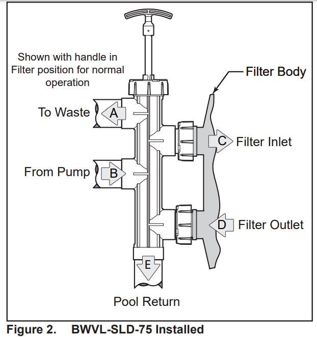
CAUTIONDo not let any adhesive get inside the slide valve body. Adhesive inside the valve body will prevent the piston from moving freely, or cause the valve to leak.
b. Normal Operation
WARNING
NEVER attempt to assemble, disassemble or adjust the filter when there is pressurized air in the system. Starting the pump while there is any pressurized air in the system can cause the filter lid to be blown off, which can cause death, serious personal injury or property damage.
- Turn off the system pump(s).
- Ensure that the slide valve handle is fully extended (handle pulled all the way up).
- Turn on the filter pump(s).
- Open the air release valve on top of the filter tank to release all pressure from inside the tank and system. Wait for all the air to evacuate the system and then close the air release valve. 5. Check the system for normal water flow.
c. Backwash Mode
- Turn off the system pump(s).
- Ensure that the slide valve handle is fully depressed with the handle and piston pushed all the way down.
- Turn the handle until the stainless steel pin on the piston locks into the positioning bracket.
- Turn on the system pump(s).
- Open the air release valve on top of the filter tank to release all pressure from inside the tank and system. Wait for all the air to evacuate the system and then close the air release valve.
- Run the system until the wastewater runs clean.• Be sure to follow any and all applicable local codes related to proper discharge/drainage of water from your pool/spa.
- Turn off the system pump(s).
- Return the slide valve handle to the normal operating position. See Figure 2.
- Turn on system pump(s) and check for normal water flow.
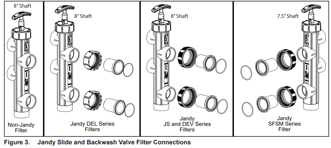
| Slide and Backwash Models | ||||
| Filter Model | BWVL-SLD | BWVL-SLD-75 | SVLV8 | SVLV2 |
| Jandy JS Series | X | |||
| Jandy DEV Series | X | |||
| Jandy SFSM Series | X | |||
| Jandy DEL Series | X | |||
| Non-Jandy Filters* | X* | |||
| *Also Requires Versa Coupler Kit 8044 |
Table 1. Slide and Backwash Models
Section 3. BWVL-SLD with DEV or JS Series Filter Installation
The following section provides instructions for installing the Jandy slide valve BWVL-SLD onto either the Jandy DEV or JS Series Filter. The instructions must be followed exactly. Read through the instructions completely before starting the procedure. Please save these instructions.The slide valve is a two-position valve. The valve handle must be fully extended or fully depressed. This valve can not be throttled.
a. Installation
WARNINGEnsure that all electrical power to the system is turned off before approaching, inspecting or troubleshooting any leaking valves that may have caused other electrical devices in the surrounding area to get wet.
- Remove the slide valve from the packaging. Twist the handle on the slide valve several times to verify that the piston moves freely. If any of the components show signs of damage please call Zodiac at 1-800-822-7933.
- Turn off all power to the system.• For new installations steps “3” through “6” may be skipped. Proceed to step 7.
- Open the pressure relief valve on top of the filter. Wait for all air to evacuate the system.
- If the filter is installed below pool level, close the suction and return line valves to isolate the filtration system or ensure that proper isolation check valves are in place.
- Drain the water from the filter. Please follow the filter manufacturers draining instructions and ensure that wastewater is disposed of properly.
- Remove the existing valve from the filter.
- Remove the two o-rings from the packaging.
- Place the o-rings on the face of the union tailpieces, where the face of the union will connect to the filter bulkheads, see Figure 4.• Make sure each o-ring is properly seated into the groove of each union tailpiece.• The slide valve has molded labels on each port.• The ports are equipped with union connections that match the connections on the filter ports.• DO NOT USE liquid thread sealant on any threaded plastic connection.
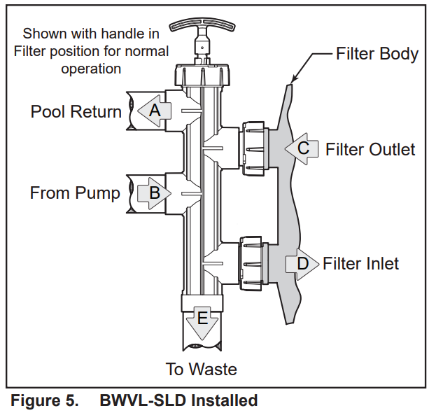
- Hold the slide valve upright and place onto the filter bulkheads. See Figure 5.
- Tighten both union nuts to secure the valve on the filter.
- Follow filter manufacturers’ instructions for filter placement on the equipment pad.
- Plumb the discharge of the pump into the slide valve inlet labeled PORT B.
- Plumb the slide valve outlet labeled PORT A to the heater or pool return lines.
- Plumb the slide valve outlet labeled PORT E to the waste line as needed. Allow the connections to dry for 24 hours.
- When the glue is dry, start the system and check for proper water flow.
- After verifying proper water flow and prior to putting the system into normal operating conditions, flush the system using Backwash mode until the wastewater is clean. Refer to Section c. for Backwash mode operation instructions.
CAUTIONDo not let any adhesive get inside the slide valve body. Adhesive inside the valve body will prevent the piston from moving freely, or cause the valve to leak.
b. Normal Operation
WARNINGNEVER attempt to assemble, disassemble or adjust the filter when there is pressurized air in the system. Starting the pump while there is any pressurized air in the system can cause the filter lid to be blown off, which can cause death, serious personal injury or property damage.
- Turn off the system pump(s).
- Ensure that the slide valve handle is fully depressed with the handle and piston pushed all the way down.
- Turn the handle until the stainless steel pin on the piston locks into the positioning bracket.
- Turn on the filter pump(s).
- Open the air release valve on top of the filter tank to release all pressure from inside the tank and system. Wait for all the air to evacuate the system and then close the air release valve.
- Check the system for normal water flow.
c. Backwash Mode WARNINGNEVER attempt to assemble, disassemble or adjust the filter when there is pressurized air in the system. Starting the pump while there is any pressurized air in the system can cause the filter lid to be blown off, which can cause death, serious personal injury or property damage.
- Turn off the system pump(s).
- Ensure that the slide valve handle is fully extended (handle pulled all the way up).
- Turn on the system pump(s).
- Open the air release valve on top of the filter tank to release all pressure from inside the tank and system. Wait for all the air to evacuate the system and then close the air release valve.
- Run the system until the wastewater runs clean. · Be sure to follow any and all applicable local codes related to proper discharge/drainage of water from your pool/spa.
- Turn off the system pump(s).
- Return the slide valve handle to the normal operating position. See Figure 5.
- Turn on system pump(s) and check for normal water flow.
Section 4. SVLV8 with DELSeries Filter Installation
The following section provides instructions for installing the Jandy slide valve SVLV8 onto the DEL Series Filter. The instructions must be followed exactly. Read through the instructions completely before starting the procedure. Please save these instructions.The slide valve is a two-position valve. The valve handle must be fully extended or fully depressed. This valve can not be throttled.
a. InstallationWARNINGEnsure that all electrical power to the system is turned off before approaching, inspecting or troubleshooting any leaking valves that may have caused other electrical devices in the surrounding area to get wet.
- Remove the slide valve from the packaging. Twist the handle on the slide valve several times to verify that the piston moves freely. If any of the components show signs of damage pleasecall Zodiac at 1-800-822-7933.
- Turn off all power to the system.• For new installations steps “3” through “6” may be skipped. Proceed to step 7.
- Open the pressure relief valve on top of the filter. Wait for all air to evacuate the system.
- If the filter is installed below pool level, close the suction and return line valves to isolate the filtration system or ensure that proper isolation check valves are in place.
- Drain the water from the filter. Please follow the filter manufacturers draining instructions and ensure that wastewater is disposed of properly.
- Remove the existing valve from the filter.
- Remove the two o-rings from the packaging.
- Place the o-rings on the face of the union tailpieces, where the face of the union will connect to the filter bulkheads, see Figure 6.• Make sure each o-ring is properly seated into the groove of each union tailpiece.• The slide valve has molded labels on each port.• The ports are equipped with union connections that match the connections on the filter ports.• DO NOT USE liquid thread sealant on any threaded plastic connection.
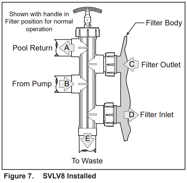
- Hold the slide valve upright and place it onto the filter bulkheads. See Figure 7.
- Tighten both union nuts to secure the valve on the filter.
- Follow filter manufacturers’ instructions for filter placement on the equipment pad.
- Plumb the discharge of the pump into the slide valve inlet labeled PORT B.
- Plumb the slide valve outlet labeled PORT A to the heater or pool return lines.
- Plumb the slide valve outlet labeled PORT E to the waste line as needed. Allow the connections to dry for 24 hours.
- When the glue is dry, start the system and check for proper water flow.
- After verifying proper water flow and prior to putting the system into normal operating conditions, flush the system using Backwash mode until the wastewater is clean. Refer to Section c. for Backwash mode operation instructions.
CAUTIONDo not let any adhesive get inside the slide valve body. Adhesive inside the valve body will prevent the piston from moving freely, or cause the valve to leak.
 b. Normal Operation
WARNINGNEVER attempt to assemble, disassemble or adjust the filter when there is pressurized air in the system. Starting the pump while there is any pressurized air in the system can cause the filter lid to be blown off, which can cause death, serious personal injury or property damage.
- Turn off the system pump(s)
- Ensure that the slide valve handle is fully depressed with handle and piston pushed all the way down.
- Turn the handle until the stainless steel pin on the piston locks into the position bracket.
- Turn on the filter pump(s).
- Open the air release valve on top of the filter tank to release all pressure from inside the tank and system. Wait for all the air to evacuate the system and then close the air release valve.
- Check the system for normal water flow.
c. Backwash Mode
WARNING NEVER attempt to assemble, disassemble or adjust the filter when there is pressurized air in the system. Starting the pump while there is any pressurized air in the system can cause the filter lid to be blown off, which can cause death, serious personal injury or property damage.
- Turn off the system pump(s).
- Ensure that the slide valve handle is fullyextended (handle pulled all the way up).
- Turn on the system pump(s).
- Open the air release valve on top of the filtertank to release all pressure from inside the tank and system. Wait for all the air to evacuate the system and then close the air release valve
- Run the system until the wastewater runs clean.• Be sure to follow any and all applicable local codes related to proper discharge/drainage of water from your pool/spa.
- Turn off the system pump(s).
- Return the slide valve handle to the normal operating position. See Figure 7.
- Turn on system pump(s) and check for normal water flow.
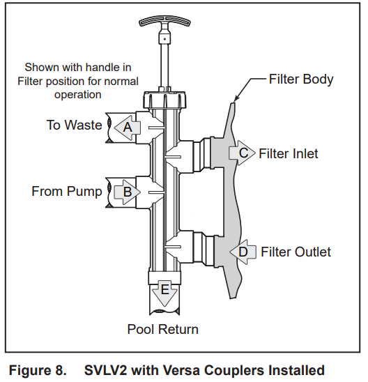
Section 5. SVLV2 with Non-Jandy Filter Installation.
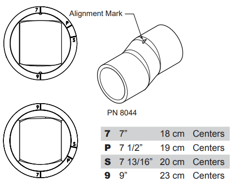
a. Versa Coupler p/n 8044Versa Plumb® connectors can be used to on filters with port distances from 7″ to 9″ centers. The valve port faces have four alignment marks. By using the alignment marks on the versa coupler the following port distances can be achieved:
- Measure the distance between the inlet and outlet ports on the filter body.
- Using the Versa Plumb connectors set the alignment marks to the required position based on the measurements provided above.
- Align each versa-coupler to the filter and the slide valve prior to gluing the assembly. When the parts are in alignment, mark each piece to ensure correct reassembly.
 Measure the distance between the inlet and outlet ports on the filter body.
b. Installation
WARNINGEnsure that all electrical power to the system is turned off before approaching, inspecting or troubleshooting any leaking valves that may have caused other electrical devices in the surrounding area to get wet.The following section provides instructions for installing the Jandy slide valve SLVL2 onto a non-Jandy filter. This requires at least one versa coupler p/n 8044. The instructions must be followed exactly. Read through the instructions completely before starting the procedure. Please save these instructions.The slide valve is a two-position valve. The valve handle must be fully extended or fully depressed. This valve can not be throttled.
- Remove the slide valve from the packaging. Twist the handle on the slide valve several times to verify that the piston moves freely. If any of the components show signs of damage, please call Zodiac at 1-800-822-7933.
- Turn off all power to the system.• For new installations steps “3” through “6” may be skipped. Proceed to step 7.
- Open the pressure relief valve on top of the filter. Wait for all air to evacuate the system.
- If the filter is installed below pool level, close the suction and return line valves to isolate the filtration system or ensure that proper isolation check valves are in place.
- Drain the water from the filter. Please follow the filter manufacturers draining instructions and ensure that wastewater is disposed of properly.
- Remove the existing valve from the filter.
- Follow filter manufacturers instructions for filter placement on the equipment pad.
- Slide one (1) versa-coupler into PORT C and one (1) into PORT D on the slide valve. See Figure 8.
- Hold the slide valve up to the filter and twist the versa-couplers until they slide into the filter inlet and outlet ports.
- Remove the valve from the filter. Clean the versa-couplers and glue them onto the valve using the alignment marks as a reference.
- Clean the versa-coupler and glue onto the filter, or install 2″ union tailpieces and union nuts• The slide valve has molded labels on each port.• DO NOT USE liquid thread sealant on any threaded plastic connection.• If glued, hold the coupler in place for a minimum of one (1) minute.
- Plumb the discharge of the pump into the slide valve inlet labeled PORT B.
- Plumb the slide valve outlet labeled PORT A to the waste line as needed.
- Plumb the slide valve outlet labeled PORT E to the heater or pool return lines.
- Allow the connections to dry for 24 hours.
- When the glue is dry, start the system and check for proper water flow.
- After verifying proper water flow and prior to putting the system into normal operating conditions, flush the system using Backwash mode until the wastewater is clean. Refer to Section c. for Backwash mode operation instructions.
CAUTIONDo not let any adhesive get inside the slide valve body. Adhesive inside the valve body will prevent the piston from moving freely, or cause the valve to leak.
c. Normal Operation
WARNINGNEVER attempt to assemble, disassemble or adjust the filter when there is pressurized air in the system.Starting the pump while there is any pressurized air in the system can cause the filter lid to be blown off, which can cause death, serious personal injury or property damage.
- Turn off the system pump(s).
- Ensure that the slide valve handle is fully extended (handle pulled all the way up).
- Turn on the filter pump(s).
- Open the air release valve on top of the filter tankto release all pressure from inside the tank and system. Wait for all the air to evacuate the system and then close the air release valve.
- Check the system for normal water flow.
d. Backwash Mode
WARNING NEVER attempt to assemble, disassemble or adjust the filter when there is pressurized air in the system. Starting the pump while there is any pressurized air in the system can cause the filter lid to be blown off, which can cause death, serious personal injury or property damage.
- Turn off the system pump(s).
- Ensure that the slide valve handle is fully depressed with the handle and piston pushed all theway down.
- Turn the handle until the stainless steel pin on the piston locks into the positioning bracket.
- Turn on the system pump(s)
- Open the air release valve on top of the filter tank to release all pressure from inside the tank and system. Wait for all the air to evacuate the system and then close the air release valve.
- Run the system until the wastewater runs clean.• Be sure to follow any and all applicable local codes related to proper discharge/drainage of water from your pool/spa.
- Turn off the system pump(s).
- Return the slide valve handle to the normal operating position. See Figure 8.
- Turn on system pump(s) and check for normal water flow.
Section 6. Servicing
WARNINGNEVER attempt to assemble, disassemble or adjust the filter when there is pressurized air in the system.Starting the pump while there is any pressurized air in the system can cause the filter lid to be blown off, which can cause death, serious personal injury or property damage.
- Turn off the system pump(s).
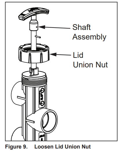
- Loosen the lid union nut. See Figure 9.
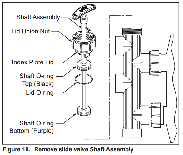
- Grab the slide valve handle and pull the shaft assembly out of the valve. See Figure 10.
- Inspect the shaft and the o-rings for wear, cuts, cracks, and debris. If the o-rings show any sign of wear or damage, replace them with a Jandy o-ring and Roll Pin Replacement Kit.NOTE The o-ring inspection includes the lid o-ring. Please be aware that the roll pins are different lengths; the handle roll pin is 1″ long and the shaft roll pin is 13/16″long.
- Wash the shaft and o-rings with clean water and dry with a lint-free cloth. Ensure that all debris is removed.
- Wash the lid surface of the valve (where the lid o-ring is seated) and dry with a lint-free cloth. Ensure that all debris is removed.
- Lubricate o-rings with 100% silicone grease lubricant, like Magic Lube® II. Do not use any lubricant containing petroleum products.
- Place the shaft back into the slide valve and tighten the lid union nut.
- Return the slide valve handle to the normal operating position. Refer to the appropriate section depending on your specific valve p/n and filter (reference page 2 of this manual).
- Turn on system pump(s) and check for normal water flow.
Section 7. Winterizing
CAUTIONIf not properly winterized, damage to the slide valve will occur, which will increase the potential of injury.
WARNINGNEVER attempt to assemble, disassemble or adjust the filter when there is pressurized air in the system.Starting the pump while there is any pressurized air in the system can cause the filter lid to be blown off, which can cause death, serious personal injury or property damage.
- Turn off the system pump(s).
- Open the air release valve on top of the filter tank to release all pressure from inside the tank and system. Wait for all the air to evacuate the system and then close the air release valve.
- Loosen the lid union nut. See Figure 9.
- Grab the slide valve handle and pull the shaft assembly out of the valve. See Figure 10.
- Allow all water to drain out the valve.
- When it is confirmed that there is no water left in the valve, place the shaft back into the slide valve and tighten the lid union nut.
- Position the slide valve in Backwash mode.
Section 8. Performance
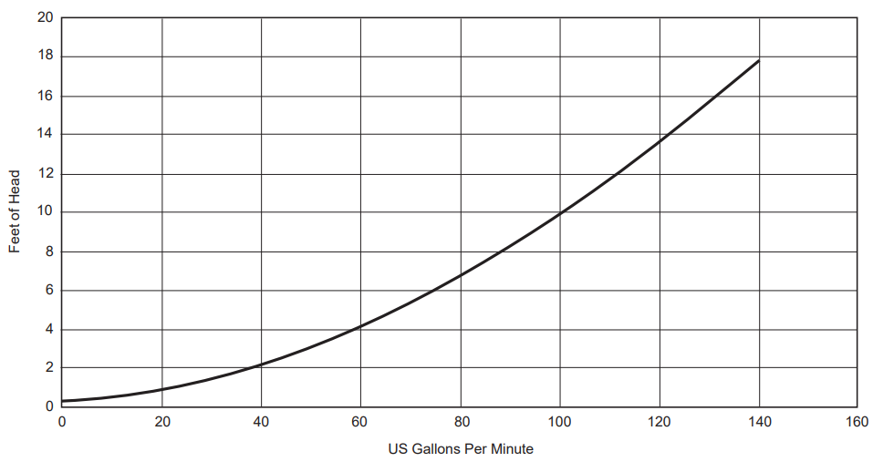
Figure 11. Slide Valve Head Loss Curve (slide valve with SFSM Filter Data Shown)
Section 9. Slide Valve Exploded View and Replacement Parts List
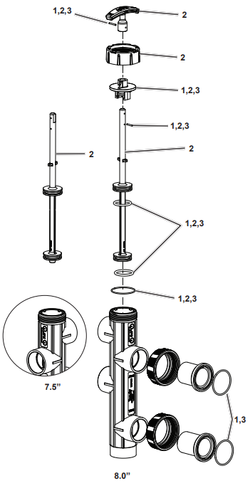 |
KeyNo. | Description | Qty. | OrderPart No. |
| 1 | Rebuild Kit (O-rings, Roll Pinsand Index Plate/Lid)(BWVL-SLD) | R0473000 | ||
| O-ring, Lid | 1 | |||
| O-ring, Shaft, Top, Black | 1 | |||
| O-ring, Shaft, Bottom, Purple | 1 | |||
| O-ring, Union Tail Piece | 2 | |||
| Roll Pin, Handle (1”) | 1 | |||
| Roll Pin, Shaft ( 13 /”) | 1 | |||
| 1+F6:H21 | 1 | |||
| 2 | Shaft Replacement Kit | R0442200 | ||
| Shaft, 8.0” Spacing | 1 | |||
| Shaft, 7.5” Spacing | 1 | |||
| Handle | 1 | |||
| Roll Pin, Handle (1″) | 1 | |||
| Roll Pin, Shaft ( 13 /16″) | 1 | |||
| Index Plate/Lid | 1 | |||
| Lid Union Nut | 1 | |||
| O-ring, Lid | 1 | |||
| O-ring, Shaft, Top, Black | 1 | |||
| O-ring, Shaft, Bottom, Purple | 1 | |||
| 3 | O-ring and Pin Replacement Kit(SVLV8) | R0442100 | ||
| Roll Pin, Handle (1”) | 1 | |||
| Roll Pin, Shaft ( /16”) | 1 | |||
| Index Plate | 1 | |||
| O-ring, Shaft, Top, Black | 1 | |||
| O-ring, Shaft, Bottom,Purple | 1 | |||
| O-ring, Union Tail Piece | 3 |

Zodiac Pool Systems LLC2882 Whiptail Loop # 100, Carlsbad, CA 92010USA | Jandy.com | 1.800.822.7933Zodiac Pool Systems Canada, Inc.2-3365 MainwayBurlington, ON L7M 1A6 Canada1.888.647.4004 | www.ZodiacPoolSystems.ca
©2021 Zodiac Pool Systems LLC. All rights reserved. ZODIAC® is a registered trademark of Zodiac International, S.A.S.U. used under license. All other trademarks referenced herein are the property of their respective owners.H0617700_REVD
References
[xyz-ips snippet=”download-snippet”]