![]() Essential 16 Owner’s Manual:Table of ContentsModel #: CS-1610 and CS-1210www.JAR-Systems.com866.393.4202EssentialCharging StationOwner’s ManualVersion
Essential 16 Owner’s Manual:Table of ContentsModel #: CS-1610 and CS-1210www.JAR-Systems.com866.393.4202EssentialCharging StationOwner’s ManualVersion
![]()
Disclaimer: Failure to read, thoroughly understand, and follow all instructions can result in serious personal injury, damage to equipment, or voiding of factory warranty. It is the installer’s responsibility to make sure all mounting systems are properly assembled and installed using the instructions provided. This information is the intellectual property of JAR Systems LLC and may not be distributed, duplicated, or copied in part or full without written permission. Since the use of this information, the equipment connected, and the conditions by which any JAR Systems product is used are beyond the control of JAR Systems, it is the obligation of the owner and/or user to determine the correct and safe use of any equipment and product. To the extent that the law permits, any liability which may be incurred as a result of the use or future use of a product manufactured or sold by JAR Systems is limited to the cost of repairing or replacing the failed product or component at the discretion of JAR Systems either within, or outside of warranty periods, and does not extend to any loss or damage which may be caused as a consequence of misuse or failure of the equipment or product or the information contained herein. JAR Systems shall not, in any event, be liable for economic loss of profits, indirect, special, bodily injuries, or consequential damages. Specifications and images are for illustration purposes only. The final product may differ and is subject to change without notice.
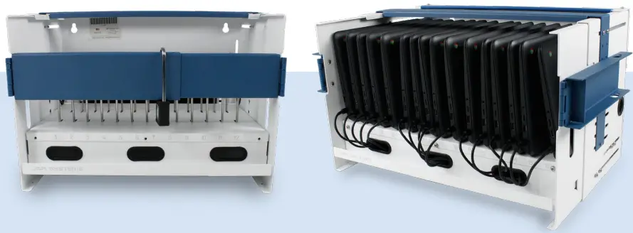
The Essential Charging Station is an ultra-flexible charging solution designed to make your life easier. Maximize space with a compact, lightweight charging station that conveniently mounts to walls or desktops. The Essential Charging Station efficiently charges up to 12 or 16 devices of any type, all without breaking the bank.
Included with the Essential Charging Station
| Main Components1. (1) Chassis2. (1) Top Locking Bar3. (1) Tray4. Stainless Steel Dividers(11 for CS-1210, 15 for CS-1610)5. (1) Chassis Rubber Bumper6. (1) Padlock With (2) Keys7. (2) Front Locking Arms8. (1) T25H Torx Key9. (1) Power Strip(12 Outlet for CS-1210, 16 Outlet for CS-1610) | Hardware PacketA1. (11) Short Screws and WashersB2. (8) Long Screws and WashersC3. (4) Power Strip Screws with NutsD4. (4) Rubber FeetE5. (4) Screws for Rubber FeetF6. (4) Clear Cable Holder ClipsG7. 3 Sets of (4) Wall Mounting ScrewsH8. Spare HardwareI9. (1) Drill Bit |
Getting StartedPrepare the Chassis
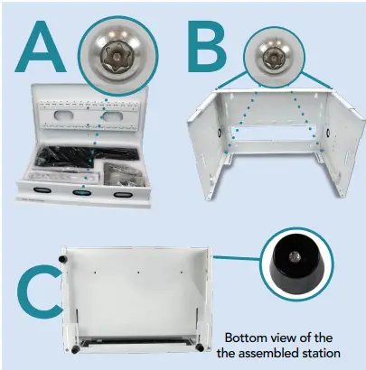
A. Remove contents of the carton and separate the major components. Use the T25H Torx key that is packaged with the manual to remove the screw and washer from the center of the tray lid. Remove the contents from the tray.B. Extend the sides of the chassis out at right angles and tighten the pre-installed screws on the corner of each side. Each side has one on the top and one on the bottom (4 screws total).CS-1210’s right panel is detached for shipping, attach with 2 [B2] screws and washers.C. The supplied rubber feet [D4], [E5] can be optionally installed in the four holes on the bottom side of the unit beside the holes used for securing the unit to a horizontal surface.
Secure Chassis to a Wall or Desk (Optional)
D. If the unit will be used on a table, desk, or countertop: The unit may be optionally secured to the surface by inserting 4 screws appropriate for the surface type through the bottom side of the chassis.E. To mount the station to a wall: Use the supplied template as a guide for your screw location on the wall. Other tools helpful to mounting: a level, and a stud finder, and a pencil to mark mounting points over studs in the wall.
WARNING: Failure to provide adequate structural strength for this mounting system can result in serious personal injury or damage to equipment. It is the installer’s responsibility to make sure the structure to which this mounting system is attached can support five times the combined weight of all equipment. Reinforce the structure as required before installing. The wall to which the mount is being attached may have a maximum drywall thickness of 5/8” (1.6cm). Always ensure that proper hardware is used for the wall surface type. Never operate this mounting system if it is damaged. Contact JAR Systems for replacement or repair.
Reversible Power StripF. The power strip can be mounted on either the front (position #1) or back (position #2) side by reversing the mounting brackets.Loosen the three screws on each side, rotate the bracket, and replace the screws.
Install the Power StripG. Install the power strip in one of the following positions with [C3] 4 screws and nuts.
- Recommended for smaller devices.
- Recommended for most desktop users.
- Alternate position for desktop usage.
- Recommended for most wall-mount usage.
- Alternate position for wall-mount usage.
Mount the Tray to the ChassisH. Pull out the sides of the chassis to the depth needed for your device. Loosen the pre-installed screws on the sides of the sides will not slide out. Note: To prevent unauthorized removal of devices, do not extend the sides further than needed to fit the devices.
I. Rest the tray on the tabs near the front of the chassis. Insert 4 [B2] screws with plastic washers through the chassis and into the backside of the tray. (2 screws on each side).J. Open the tray and insert 2 [A1] screws and washers through the tray and into the tabs on the chassis.
Install Rubber BumperK. To protect your devices from hitting the back edge of the chassis, utilize the supplied rubber bumper.
Install the Top Security Bar (Optional)L. For security, place the top locking bar at the lowest height that will fit over the devices. Use 2 [B2] screws on the top two holes on the outside and 1 [A1] screw should be secured from the inside of the chassis to prevent removal, on both sides.
Insert the Dividers into the TrayM. Remove the pre-installed divider locks from under the shelf. Insert the dividers into the slots on the shelf. Ensure that all dividers are properly seated and re-install the divider locks beneath the shelf using 6 [A1] screws.
Install Locking Arms (Optional)N. Install the front locking arms using 2 [A1] screws on each side. Screws for the locking arms should be installed from the inside of the chassis to prevent removal.O. Using the included padlock and keys with the front locking arms can secure the station by looping it through the holes when they align. Using the padlock upside-down may make the lock easily accessible.
Cable ManagementP. Place a security screw in the side of the chassis to hold the tray open during the wiring process.Q. Determine the length of cable that is needed to reach from the tray to the devices.R. Determine the best method of arranging the cables that come with your device.TIP: Adapters can often be installed as they come bundled in the box. If the cables are not bundled at all, twist ties or Velcro ties are helpful. If the devices have larger AC adapters (5”x 2”x 1.25” or larger) the adapters will fit snugly in the tray. In this case, it may be best to arrange most of the adapters as far back in the tray as possible from left to right, flipping bout half on their side. Contact JAR Systems for additional assistance.
S. Plug the charger into the power strip.For best results, bundle any excess cable length if it is not already.T. (OPTIONAL) Place a security screw [B2] in the center of the shelf to prevent adapters from being removed or tampered with.
Warnings
Proper Usage and SafetyThis unit must always be used by adults or with adult supervision. Do not leave the unit unattended in areas where children have access.Do not use this unit outdoors.Liquids should not be stored in, set on, or placed inside this unit.Exceeding the weight capacity can result in serious personal injury or damage to equipment. It is the installer’s responsibility to make sure the combined weight of all components attached to this mount does not exceed 100 lbs.If the unit is being used or transported on an AV cart or charging cart, the unit must be secured down to the cart.
WarrantyCovers any defects in material or workmanship and extends to the original consumer of the product only. JAR Systems LLC will replace the product with a new or refurbished product, repair the product, send replacement parts, or refund the purchase price of the product, at JAR Systems LLC’s discretion.This warranty does not cover accidental damage, unreasonable use, neglect, tampering, or other causes not arising from defects in material or workmanship.Any implied warranties last only as long as the warranty periods listed above except where state law does not allow limitations on how long an implied warranty lasts.This includes but is not limited to the implied warranties of merchantability and fitness. JAR Systems LLC’s responsibility is limited to the actions listed above and nothing else.This warranty does not cover, and JAR Systems LLC will not be responsible for, any damages due to loss of use of the product, or any other costs or expenses incurred by you or anyone else who uses the product, whether due to defects, breach of contract, negligence, strict liability or otherwise.JAR Systems is not liable for any indirect, special, incidental, or consequential damages related to the product or this warranty. Some states do not allow exclusions or limitations on consequential or incidental damages, so these limitations or exclusions may not apply.This warranty gives you specific legal rights and you may also have other rights that vary from state to state. This warranty is governed by the laws of Florida, excluding its conflict of laws principles, unless your state requires that its law be used.
 report this ad
2020 © JAR Systems LLC reserves all rights to the copy and content of this manual
References
[xyz-ips snippet=”download-snippet”]