![]()
MANUAL 43107ZW3015
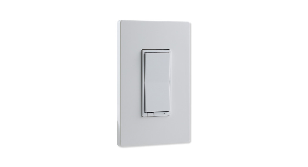
In-Wall0-10V Smart Dimmer
READ IT OR WATCH IT
Read instructions or watch the easy-to-follow videos. Scan QR code or visit https://byjasco.com/43107iConvert any smart control* to a multi-location switch*For a list of compatible devices, visit ezzwave.com
To purchase an add-on switch or for more details, visit ezaddonswitch.com.
Each smart control supports up to 4 add-on switches ezaddonswitch.com
Purchase additional items at EZzwave.com or visit your local retailer.
Tools you will need

IMPORTANT!The dimmer is designed only for use with permanently installed fixtures.
Getting to know your new Z-Wave device
- Turn-ON/OFF and adjust dim levels manually or remotely via the Z-Wave controller
- Can be included in multiple groups and scenes
- May be used in the single-pole installation or with up to four add-on switches (#46561) in 3-way or 4-way wiring configurations
- Auto line/load detection
- Uses a standard toggle wallplate for single-gang installations (wallplate not included)
- Z-Wave certified for simple pairing and integrated home automation
- Screw terminal installation — requires wiring connections for line (hot), load, neutral and ground. Traveler wire required for 3-way or 4-way installation
- This Z-Wave device has advanced features that allow you to customize your experience.These features can only be adjusted by a Z-Wave-enabled controller that supports the Z-Wave configuration command class. For a complete list of adjustable configurations, visit www.ezzwave.com/config
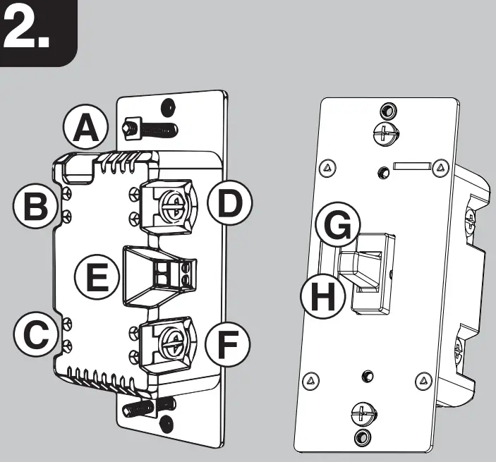
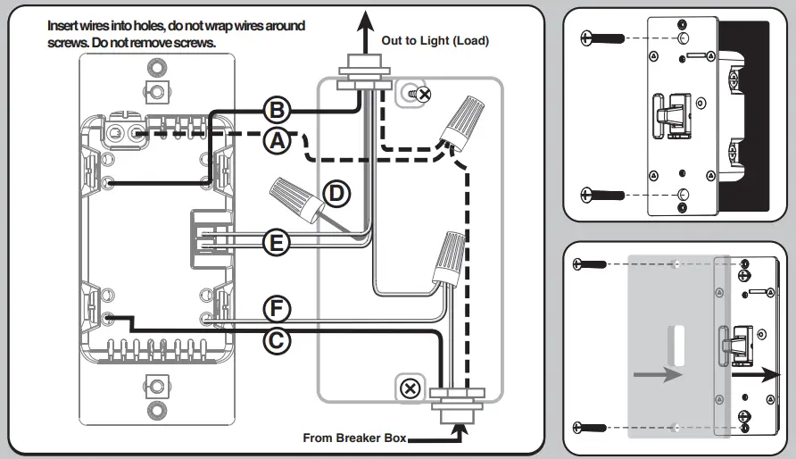
| A. Ground (Green/Bare)B. Line or Load (Black)C. Line or Load (Black)D. Traveler (Red/Other) | E. +/- (Output terminals)F. Neutral (White)G. Up — press & release to turn dimmer on, press & hold to increase brightnessH. Down — press & release to turn dimmer off, press & hold to dim |
 |
 |
WARNING — SHOCK HAZARDTurn OFF the power to the branch circuit for the switch and lighting fixture at the service panel. All wiring connections must be made with the POWER OFF to avoid personalinjury and/or damage to the switch. This device is intended for installation in accordance with the National Electric Code and local regulations in the United States or theCanadian Electrical Code and local regulations in Canada. If you are unsure or uncomfortable about performing this installation, consult a qualified electrician.Multi-switch wiringFor 3-way installations, please refer to the add-on switch (46561) manual.Single-switch wiring
- Shut off power to the circuit at the circuit breaker or fuse box.IMPORTANT! Verify power is OFF to the switch box before continuing.
- Remove wallplate.
- Remove the switch mounting screws.
- Carefully remove the switch from the switch box. DO NOT disconnect the wires.
- There are up to six screw terminals on the dimmer; these are marked:A. GROUND — Green/BareB. LINE or LOAD — Black (connected to power or lighting)C. LINE or LOAD — Black (connected to power or lighting)D. TRAVELER — Red/Other (only in 3-way installations)E. +/- output terminalsF. NEUTRAL — WhiteMatch these screw terminals to the wires connected to the existing switch.
- Disconnect the wires from the existing switch. Label wires according to the previous terminal connection.
Observe important wiring information
IMPORTANT! This dimmer is rated for and intended to only be used with copper wire.
Wire gauge requirementsUse 14AWG or larger wires suitable for at least 80° C for supplying line (hot), load, neutral, ground and traveler connections. The +/- output terminals require 26-16AWG.Wire strip lengthAttach using the enclosure’s holes, strip insulation 5/8in. (16mm).UL specifies the tightening torque for the screws is 14Kgf-cm (12lbf-in).
- Connect the green or bare copper ground wire to the GROUND terminal.
- Connect the black wire from the light to either LINE/LOAD terminal.
- Connect the black wire from the electrical service panel (hot) to the other LINE/LOAD terminal.4. Connect the white wire to the NEUTRAL terminal (use a jumper wire if needed).NOTE: The traveler terminal is only used for 3-way or 4-way wiring and should remain insulated if the dimmer is being installed in a 2-way system (one dimmer & one load).
- Connect the + wire from the light fixture to the + on the dimmer using a small, flathead screwdriver.
- Connect the – wire from the light fixture to the – on the dimmer using a small, flathead screwdriver.
- Insert dimmer into the switch box being careful not to pinch or crush wires.
- Dimmer must be independently mounted (vertical position only).
- Secure the dimmer to the box using the supplied screws.
- Mount the wallplate.
- Reapply power to the circuit at the fuse box or circuit breaker and test the system.
Basic operationThe connected light can be turned ON/OFF and adjust dim levels in two ways:
- Manually from the front panel of the in-wall dimmer.
- Remotely with a Z-Wave controller.
Manual controlThe front panel toggle allows the user to turn ON/OFF the connected fixture.
- To turn the connected fixture ON, press up and release the toggle.
- To turn the connected fixture OFF, press down and release the toggle.
Adjust dim level
- To increase brightness, press up and hold the toggle.
- To decrease brightness, press down and hold the toggle.
Cycle LED lightAn LED shines behind the toggle to act as a guiding light or status indicator.How to cycle between options: Press up three times, then down one time quickly
- LED is OFF all the time (default)
- LED is ON all of the time (illuminates dimmer in the dark)
- LED is ON when the load is OFF (guide light in the dark)
- LED is ON when the load is ON (indicates the dimmer is ON)
LED bulb adjustmentsNot all LED bulbs are made the same, and performance varies between dimmer brands. This can cause adverse bulb behavior, such as flickering or strobing. To account for this scenario, this dimmer features adjustable dim and brightness thresholds to allow setting minimum and maximum levels.Minimum dim threshold
- Press the OFF button four times, then the ON button once quickly.
- Light starts at the most recent dim level (default — 1%).
- Press the ON or OFF button until the bulb reaches desired brightness without flickering.
- The LED stops flashing 10 seconds after releasing the button to indicate the minimum threshold is set.Note: This can be set by Z-Wave configuration parameter 30/size: 1 byte/values 1-99 (default — 1)
Maximum brightness threshold
- Press the ON button four times, then the OFF button once quickly.
- Light starts at the most recent brightness (default — 99%)
- Press the ON or OFF button until the bulb reaches desired brightness without flickering.
- The LED stops flashing 10 seconds after releasing the button to indicate the maximum threshold is set.Note: This can be set by Z-Wave configuration parameter 31/size: 1byte/values 1-99 (default —99)
Adding your device to a Z-Wave network
- Follow the instructions for your Z-Wave certified controller to add a device to the Z-Wave network.
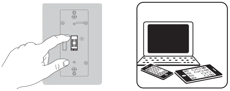
- Once the controller is ready to add your device, press up and release the toggle.
- The controller’s app will indicate if it discovers the switch. If prompted by the controller to enter the S2 security code, refer to the QR code/security number on the side of the box or the QR code label on the product (see Figure 1). Enter the 5-digit code
Please reference the controller’s manual for instructions.You have complete control to turn your fixture ON/OFF/DIM and create groups, scenes, schedules, and interactive automation programmed by your controller.If your Z-Wave certified controller features remote access, you can control your fixture from your mobile devices.NOTE: SmartStart enabled products can be added into a Z-Wave network by scanning the QR code on the product with a controller providing SmartStart inclusion. No further action is required and the SmartStart product will be added automatically within 10 minutes of being switched on in the network vicinity.
To remove and reset the device
- Follow the instructions for your Z-Wave certified controller to remove a device from theZ-Wave network.
- Once the controller is ready to remove your device, press up and release the toggle.
To return your dimmer to factory defaultsQuickly press the ON (up) button three times then immediately press the OFF (down) button three times.NOTE: This should only be used if your network’s primary controller is missing or otherwise inoperable.

NOTE: Actual performance of any CFL or LED varies from bulb type to bulb type and among manufacturers. It is important to note only bulbs designed as dimmable should be used on a dimmer.To find out if your bulb is dimmable, please check the package, the bulb itself, or call the bulb manufacturer directly.For a complete list of recommended CFL/LED bulbs for this and other Z-Wave products from Jasco, please visit www.byjasco.com/z-wave
Add-on switch 46561 is required for multi-switch installationsConnecting the traveler terminal of this dimmer to a standard switch will cause damage or result in improper function. If this dimmer is a part of a multi-switch installation, do not connect the traveler wire or apply power until add-on switches (46561) are correctly installed. For more information on 3-way or 4-way installations, view the manual with the add-on switch.
![]() Z-WAVE INTEROPERABILITYThis product can be included and operated in any Z-Wave network with other Z-Wave certified devices from other manufacturers and/or other applications. All nonbattery-operated nodes within the network will act as repeaters regardless of vendor to increase the reliability of the network.
Z-WAVE INTEROPERABILITYThis product can be included and operated in any Z-Wave network with other Z-Wave certified devices from other manufacturers and/or other applications. All nonbattery-operated nodes within the network will act as repeaters regardless of vendor to increase the reliability of the network.
This device supports Association Command Class (3 Groups)
- Association Group 1 supports Lifeline, Multi-level Switch report
- Association Group 2 supports Basic Set and is controlled with the local load
- Association Group 3 supports Basic Set and is controlled by double-pressing the ON or OFF button
- Each Association Group supports 5 total nodesFor more details, visit ezzwave.com
 DO NOT RETURN THIS PRODUCT TO THE STORE NE RETOURNEZ PAS CE PRODUIT AU MAGASIN NO DEVUELVA ESTE PRODUCTO A LA TIENDA
If you have any problems or questions, contact our U.S.-based Consumer Care at 1-800-654-8483, option 1, Monday–Friday, 7 AM–8 PM Central Time.For the most up-to-date product support, accessories, electronic (PDF) format manuals, and more, visit www.byjasco.com/support.
- No user-serviceable parts in this unit.
WARNING
RISK OF FIRERISK OF ELECTRICAL SHOCKRISK OF BURNSCONTROLLING APPLIANCESCAUTION:
- ONLY USE TO CONTROL DIMMABLE CFL/LED BULBS
- DO NOT EXCEED RATINGS
- DO NOT USE TO CONTROL ANY DEVICE WHERE UNINTENDED OPERATION COULD CAUSE UNSAFE CONDITIONS (HEAT LAMP, SUN LAMP, ETC.)
- DO NOT USE TO CONTROL RECEPTACLES
- FOR INDOOR USE ONLY
NOT FOR USE WITH MEDICAL OR LIFE SUPPORT EQUIPMENTZ-WAVE ENABLED DEVICES SHOULD NEVER BE USED TO SUPPLY POWER TO OR CONTROL THE ON/OFF STATUS OF MEDICAL OR LIFE SUPPORTEQUIPMENT.
WARRANTY
Jasco Products Company warrants this product to be free from manufacturing defects for five years from the original date of consumer purchase. This warranty is limited to the repair or replacement of this product only and does not extend to consequential or incidental damage to other products that may be used with this product. This warranty is in lieu of all other warranties, expressed or implied. Some states do not allow limitations on how long an implied warranty lasts or permit the exclusion or limitation of incidental or consequential damage, so the above limitations may not apply to you. This warranty gives you specific rights, and you may also have other rights which vary from state to state. Please contact our U.S.-based Consumer Care at 1-800-654-8483 (option 1) between 7 AM – 8 PM, M-F, Central Time or www.byjasco.com if the unit should prove defective within the warranty period.
Jasco Products Company LLC, Building B10 E. Memorial Rd. Oklahoma City, OK 73114.
SPECIFICATIONS
 report this ad
ZW3015Power: 120/277VACSignal (frequency): 908.4/916MHzMaximum loads: “960VA @ 120VAC” and “1385VA @ 277VAC”Range: Up to 150ft. line of sight between the wireless controller and the closest Z-Wave receiver moduleOperating temperature range: 32-104° F (0-40° C)Use 14-12AWG wires suitable for at least 80° CThe +/- output terminals require 26-16AWGFor indoor use onlySpecifications subject to change without notice due to continuing product improvement
FCC/IC
This device complies with Part 15 of the FCC and Industry Canada license-exempt RSS standards.Operation is subject to the following two conditions:(1) this device may not cause harmful interference, and (2) this device must accept any interference received, including interference that may cause undesired operation.FCC NOTE: The manufacturer is not responsible for any radio or TV interference caused by unauthorized modifications to this equipment. Such modifications could void the user’s authority to operate the equipment.NOTE: This equipment has been tested and found to comply with the limits for a Class B digital device, pursuant to Part 15 of the FCC Rules. These limits are designed to provide reasonable protection against harmful interference in a residential installation. This equipment generates, uses, and can radiate radio frequency energy, and if not installed and used in accordance with the instructions, may cause harmful interference to radio communications. However, there is no guarantee interference will not occur in a particular installation. If this equipment does cause harmful interference to radio or television reception, which can be determined by turning the equipment off and on, the user is encouraged to try to correct the interference by one or more of the following measures:— Reorient or relocate the receiving antenna.— Increase the separation between the equipment and receiver.— Connect the equipment into an outlet on a circuit different from which the receiver is connected.— Consult the dealer or an experienced radio/TV technician for help.Important note: To comply with the FCC RF exposure compliance requirements, no change to theantenna or the device is permitted. Any change to the antenna or the device could result in the device exceeding the RF exposure requirements and void the user’s authority to operate the device.
Responsible Party – US Contact InformationEstados UnidosFCC — U2ZZW3015Jasco Products Company | Model: ZW3015/4310710 E. Memorial Rd., Oklahoma City, OK 73114 | 1-800-654-8483CAN ICES-3(B)/NMB-3(B)All brand names shown are trademarksof their respective owners.MADE IN CHINADISTRIBUTED BY JASCO PRODUCTS COMPANY LLC,10 E. MEMORIAL RD., OKLAHOMA CITY, OK 73114.©JASCO 2020, 43107 , ZW3015 ,09/04/20 v1
References
[xyz-ips snippet=”download-snippet”]