![]() MANUAL
MANUAL
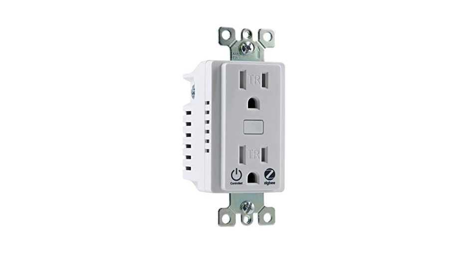
 14315ZW1002In-Wall Tamper-ResistantSmart Outlet
READ IT OR WATCH IT
https://byjasco.com/HEP-ET/00000-19999/14315/manual
Read instructions or watch the easy-to-follow videos. Scan QR code or visit goo.gl/hEdRhS
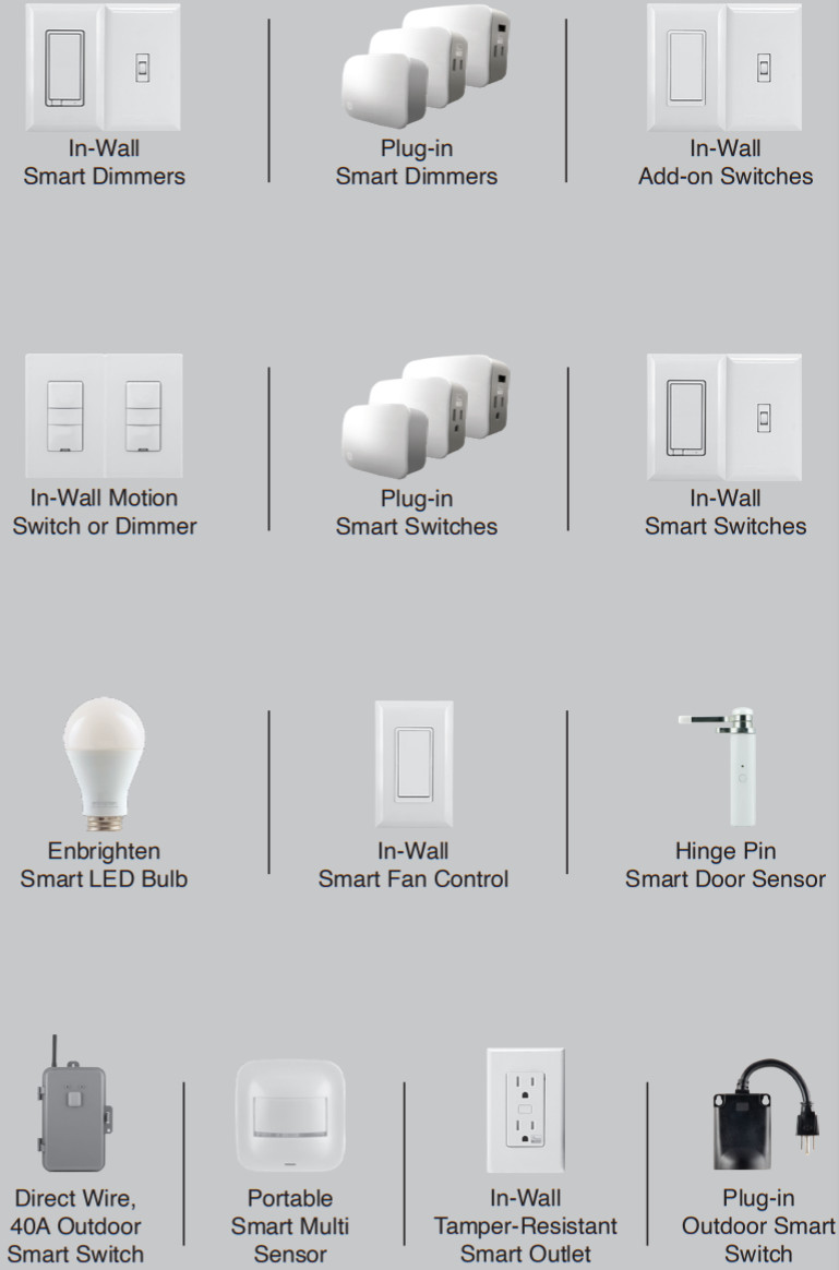
Purchase additional items at EZzwave.com or visit your local retailer.
![]() DO NOT RETURN THIS PRODUCT TO THE STORE NE RETOURNEZ PAS CE PRODUIT AU MAGASIN NO DEVUELVA ESTE PRODUCTO A LA TIENDA
DO NOT RETURN THIS PRODUCT TO THE STORE NE RETOURNEZ PAS CE PRODUIT AU MAGASIN NO DEVUELVA ESTE PRODUCTO A LA TIENDA
Questions? Contact our U.S.-based Consumer Care at 1-800-654-8483 between 7 AM-8 PM, M-F, Central Time.For the most up-to-date product support, accessories, electronic (PDF) format manuals, and more, visit www.byjasco.com/support.
- No user-serviceable parts in this unit.
WARNINGRISK OF FIRERISK OF ELECTRICAL SHOCKRISK OF BURNSCONTROLLING APPLIANCES:DO NOT EXCEED RATINGS
- DO NOT USE Z-WAVE DEVICES TO CONTROL ELECTRIC HEATERS OR ANY OTHER APPLIANCES WHICH MAY PRESENTA HAZARDOUS CONDITION DUE TO UNATTENDED OR UNINTENTIONAL OR AUTOMATIC POWER-ON CONTROL.
NOT FOR USE WITH MEDICAL OR LIFE SUPPORT EQUIPMENTZ-WAVE ENABLED DEVICES SHOULD NEVER BE USED TO SUPPLY POWER TO OR CONTROL THE ON/OFF STATUS OF MEDICAL OR LIFE SUPPORT EQUIPMENT.
WARRANTY
Jasco Products Company warrants this product to be free from manufacturing defects five years from the original date of consumer purchase. This warranty is limited to the repair or replacement of this product only and does not extend to consequential or incidental damage to other products thatmay be used with this product. This warranty is in lieu of all other warranties, expressed or implied.Some states do not allow limitations on how long an implied warranty lasts or permit the exclusion or limitation of incidental or consequential damage, so the above limitations may not apply to you.This warranty gives you specific rights, and you may also have other rights which vary from state to state. Please contact our U.S.-based Consumer Care at 1-800-654-8483 (option 1) between 7 AM – 8 PM CT or www.byjasco.com if the unit should prove defective within the warranty period.Jasco Products Company LLC, Building B 10 E. Memorial Rd. Oklahoma City, OK 73114.
SPECIFICATIONS
ZW1002Power: 120VAC, 60HzSignal (frequency): 908.4/916MHzTotal max load for both outlets: 1800W (15A) resistive loadMax load for Z-Wave controlled outlet: 960W incandescent, 1/2HP motor, or 1800W (15A) resistiveRange: Up to 150ft. line of sight between the wireless controller and the closest Z-Wave receiver moduleOperating temperature range: 32-104° F (0-40° C)For indoor use onlySpecifications subject to change without notice due to continuing product improvement

IMPORTANT!The device plugged into the Z-Wave controlled smart outlet on this module must not exceed 960W incandescent, 1800W (15A) resistive or 1/2HP motor. The total maximum rating for both outlets combined is 1800W (15A) resistive load.Getting to know your new Z-Wave device
- One Z-Wave remote-controlled outlet
- One always-ON outlet
- Remote ON/OFF control via the Z-Wave controller/network
- Manual ON/OFF control with the manual/program button
- Blue LED indicates outlet location in a dark room
- This Z-Wave device has advanced features that allow you to customize your experience. These features can only be adjusted by a Z-Wave-enabled controller that supports the Z-Wave configuration command class. See Available Configuration Parameters at the end of this guide for details.

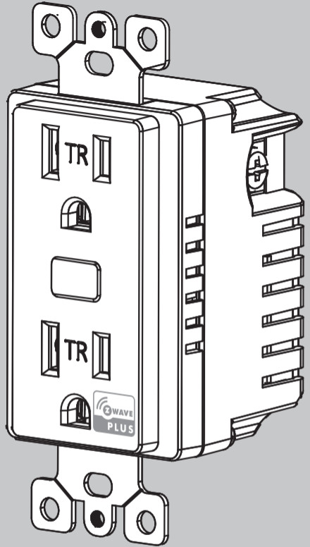
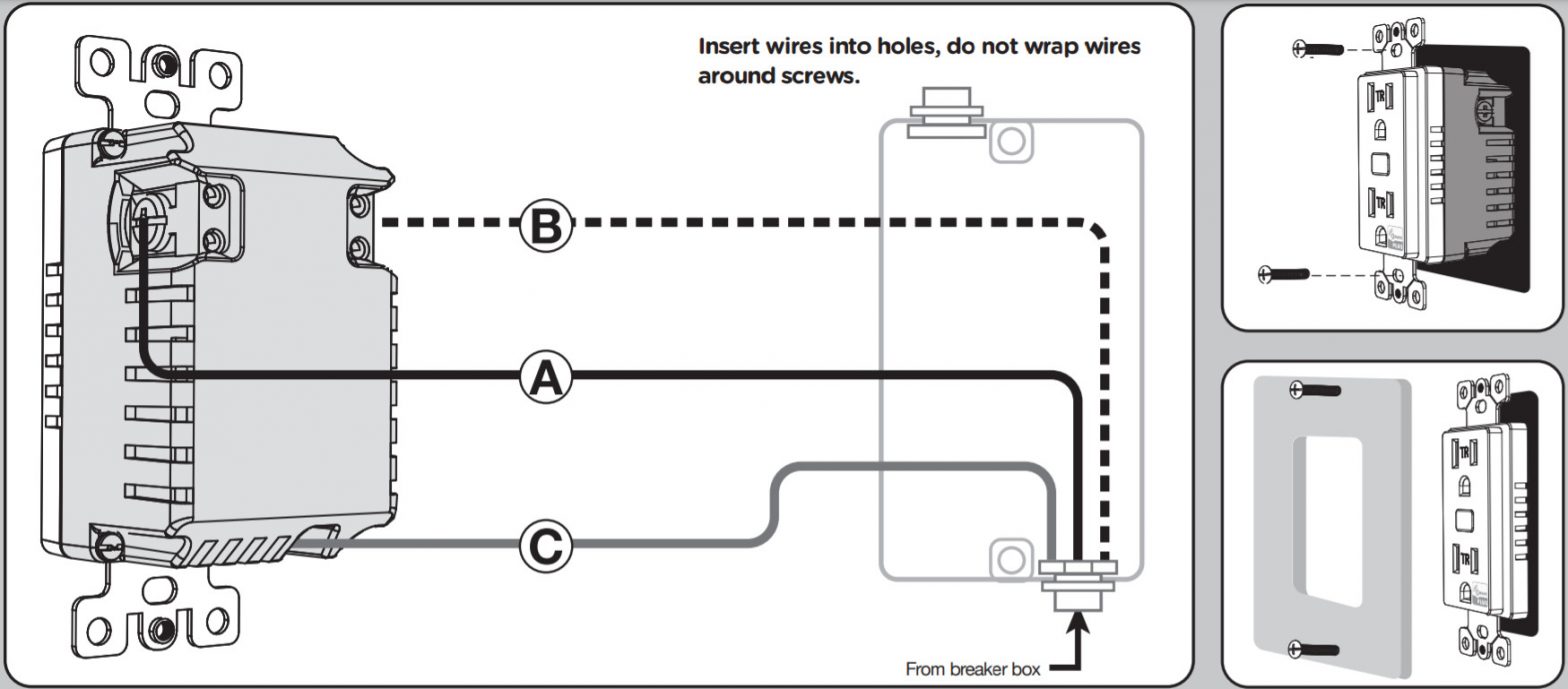
| A. Line (Hot)B. NeutralC. Ground | D. Always-on outletE. Manual/program buttonF. Z-Wave controlled outlet |
WARNING — SHOCK HAZARD
Turn OFF the power to the branch circuit for the switch and lighting fixture at the service panel.All wiring connections must be made with the POWER OFF to avoid personal injury and/or damage to the outlet.
 |
 |
Wiring
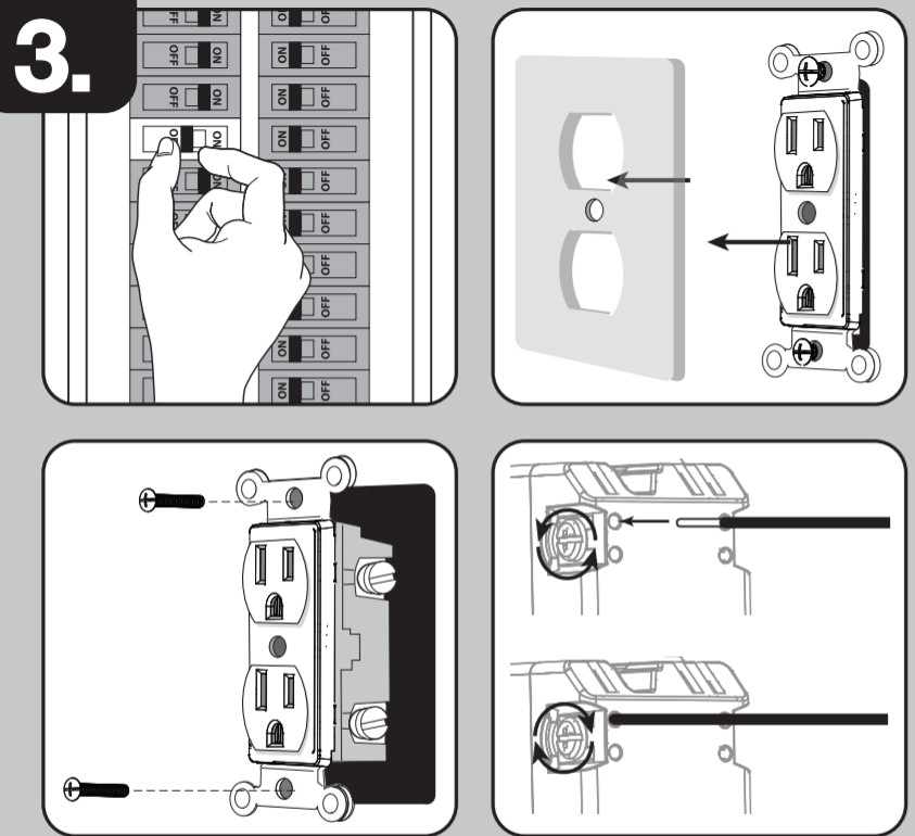
- Shut off power to the circuit at the circuit breaker or fuse box.IMPORTANT! Verify power is OFF to the switch box before continuing.
- Remove wallplate.
- Remove the outlet mounting screws.
- Carefully remove the outlet from the outlet box.
- Disconnect the wires from the existing outlet. Label wires according to the previous terminal connection.
- There are three screw terminals on the Z-Wave smart outlet; these are marked:A. LINE (Hot) — Black (connected to power)B. NEUTRAL — WhiteC. GROUND — Green/BareMatch these screw terminals to the wires connected to the existing outlet.
Observe Important Wiring Information
Always follow the recommended wire strip length (5/8in., 16mm) and wiring combination when making wiring connections. Consult an electricianwith questions or for professional installation.UL specifies the tightening torque for the screws is 14Kgf-cm (12lbf-in).IMPORTANT! The screw terminals in this receptacle are intended to only be used with copper wire. Consult a qualified electrician if you have aluminum wiring.Wire Gauge RequirementsUse 14 AWG or larger wires suitable for at least 80° C for supplying line (hot), neutral, and ground connections.
- Insert Z-Wave controlled outlet into the box being careful not to pinch or crush wires.
- Secure the smart outlet to the box using the supplied screws.
- Mount the wallplate.
- Reapply power to the circuit at the fuse box or circuit breaker and test the system.
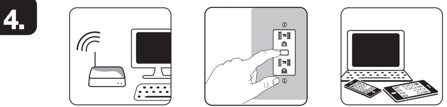
Basic Operation
The connected device can be turned ON/OFF in two ways:
- Manually from the front program button.
- Remotely with a Z-Wave controller
Manual LED Invert Method
- The device needs to be paired with a Z-Wave certified controller
- Quickly press the ON/OFF button 10 times; the light will invert if done correctly.
Adding your device to a Z-Wave network
- Follow the instructions for your Z-Wave certified controller to add a device to the Z-Wave network.
- Once the controller is ready to add your device, press the program button of the smart outlet.
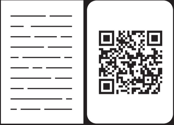
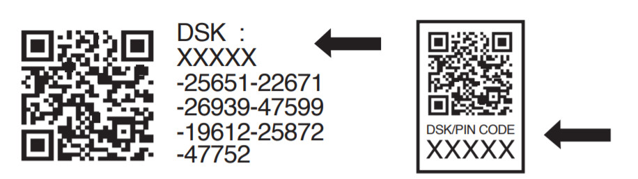
You have complete control to turn your fixture ON/OFF according to groups, scenes, schedules, and interactive automation programmed by your controller.If your Z-Wave certified controller features remote access, you can control your fixture from your mobile devices.If prompted by the controller to enter the S2 security code, refer to the QR code/security number on the side of the box or the QR code label on the product (see Figure 1). Enter the 5-digit pin code.Figure 1.
 https://byjasco.com/HEP-ET/20000-99999/39339
To remove and reset the device
- Follow the instructions for your Z-Wave certified controller to remove a device from the Z-Wave network.
- Once the controller is ready to remove your device, press and release the program button of the smart outlet.
To return your switch to factory defaultsQuickly press the program button three times. Then, press the program button for at least three seconds. The LED flashes ON/OFF five times when completed successfully.NOTE: This should only be used in the event your network’s primary controller is missing or otherwise inoperable.
Available Configuration ParametersLED LightParameter No.: 3Length = 1 bytePossible values = 0, 1 (default) or 2Value desciptions“0” – LED ON when the load is OFF, LED OFF when the load is ON“1” – LED ON when the load is ON, LED OFF when the load is OFF“2” – LED always OFF“3” – LED always ON
Z-WAVE INTEROPERABILITY
 This product can be included and operated in any Z-Wave network with other Z-Wave certified devices from other manufacturers and/or other applications. All non-battery-operated nodes within the network will act as repeaters regardless of vendor to increase the reliability of the network.
This device supports Association Command Class (3 Groups)
- Association Group 1 supports Lifeline, Binary Switch Report
- Association Group 2 supports Basic Set and is controlled with the local load
- Association Group 3 supports Basic Set and is controlled by double-pressing the On or Off button
- Each Association Group supports 5 total nodes
FCC/IC
This device complies with Part 15 of the FCC and Industry Canada license-exempt RSS standards. Operation is subject to the following two conditions:(1) this device may not cause harmful interference, and (2) this device must accept any interference received, including interference that may cause undesired operation.FCC NOTE: The manufacturer is not responsible for any radio or TV interference caused by unauthorized modifications to this equipment. Such modifications could void the user’s authority to operate the equipment.NOTE: This equipment has been tested and found to comply with the limits for a Class B digital device, pursuant to Part 15 of the FCC Rules. These limits are designed to provide reasonable protection against harmful interference in a residential installation. This equipment generates, uses, and can radiate radio frequency energy, and if not installed and used in accordance with the instructions, may cause harmful interference to radio communications. However, there is no guarantee interference will not occur in a particular installation. If this equipment does cause harmful interference to radio or television reception, which can be determined by turning the equipment off and on, the user is encouraged to try to correct the interference by one or more of the following measures:— Reorient or relocate the receiving antenna.— Increase the separation between the equipment and receiver.— Connect the equipment into an outlet on a circuit different from which the receiver is connected.— Consult the dealer or an experienced radio/TV technician for help.Important note: To comply with the FCC RF exposure compliance requirements, no change to the antenna or the device is permitted. Any change to the antenna or the device could result in the device exceeding the RF exposure requirements and void the user’s authority to operate the device.
All brand names shown are trademarks of their respective owners.MADE IN CHINADISTRIBUTED BYJASCO PRODUCTS COMPANY LLC,10 E. MEMORIAL RD.,OKLAHOMA CITY, OK 73114.©JASCO 2020 | 14315 | ZW1002 | 04/01/20 v2
References
[xyz-ips snippet=”download-snippet”]