
JBL Control 40 Series RBI Installation Guide
The Expansion of Directivity Control and Achievement of Constant Directivity in Affordable Ceiling Loudspeakers
CONTROL 20 SERIES SMALL-FORMAT CEILING SPEAKERS
Historically, one of the early steps JBL took in the direction of improved directivity control was with the Control 24 and Control 26 speakers in the 1990s. At that time, most co-axial speakers that were on the market consisted of a tweeter mounted to the end of a post, extended some distance in front of the woofer. JBL improved the coverage consistency of that form factor by adding a pattern control device to the front of the tweeter. Many people looking at the speaker mistakenly presume that it’s only function is as a horn on the tweeter for the purpose of restricting the coverage, and it does function in that way at some frequencies which need that restriction. However, at other frequencies it’s a conical diffraction slot (adapted from constant directivity horn technology) which functions to broaden the coverage of a portion of the tweeter range. This device also tends to reduce the unwanted wrap- around of the high frequencies and their reflection off the low frequency cone (which happens out of time-sync), and it loads the tweeter acoustically for better sound quality. These models are not constant directivity, but they are a step toward it, and even today they are closer to constant directivity than most of the ceiling speakers in their class
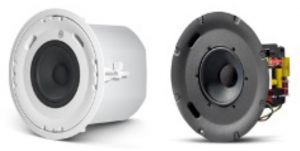
CONTROL 300 LARGE-FORMAT CEILING SPEAKERS
Control 300 Series were the first constant directivity ceiling speakers in our lineup. For the Control 300 Series of large format ceiling speakers, we developed a new design where a compression driver is mounted co-axially behind the woofer magnet, projecting part way into the pole piece of the woofer. The pole piece of the woofer is milled out to form the throat of a constant directivity horn. That matches up with the cone of the woofer, which was specially designed to be the right shape and right angle to form the bell of a constant directivity horn having the desired coverage angle. So, with an 8-inch co-ax speaker, we’ve got a full 8-inch constant directivity horn controlling the coverage of the sound coming from the high-frequency compression driver. That horn then smoothly transitions to the ceiling – which always acts as a half-space baffle – effectively utilizing the ceiling to further extending the pattern control in a smooth manner. Similarly, for the 12-inch
CONTROL 20 SERIES AND CONTROL 10 SERIES (SHOWN WITH INCLUDED GRILLE REMOVED)
horn, thus providing a smooth transition in coverage throughout the crossover range and below. In addition, because the speaker is true co-axial and source coherent – ie, with both high and low frequencies emanating from the same acoustic center in space – there is no cancellation of frequencies as you move off axis as otherwise happens with non-true-co-axialsystem, we’ve got a full 12-inch constant directivity horn on the high frequency section. Then we set the crossover point as close to the frequency where the coverage of the low- frequency driver naturally matches that of the high-frequency and non-true-source-coherent speakers due to the path-length distances changing between the sources and the listener’s ears as they move off-axis. This constant-directivity and true-co- axial design keeps the sound virtually identical (within its band of control) throughout the listening area.
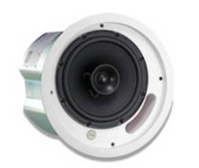
CONTROL 322C/CT CONSTANT DIRECTIVITY CO-AXIAL DRIVER, SHOWING HORN CONTOUR (BLUE LINES) AND NEODYMIUM COMPRESSION DRIVER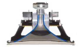
Technology White Paper: Radiation Boundary Integrator

CONTROL 321C/CT BEAMWIDTH SHOWING CONSTANT DIRECTIVITY COVERAGE FROM 1.2 KHZ THROUGH 12 KHZ. COVERAGE SPECIFIED AS BEING 90° (INDICATED BY RED LINE)
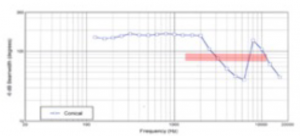
COMPETITIVE BRAND’S BEAMWIDTH CHART, SHOWING INCONSISTENT COVERAGE. SAME PRICE. SPEAKER CLAIMS 90° COVERAGE (INDICATED BY RED LINE)
AWC CONSTANT DIRECTIVITY ALL-WEATHER COMPACT SPEAKERS
That same true co-axial, source-coherent, constant directivity driver design was applied to the AWC All-Weather Compact speakers, extending constant directivity coverage into the compact high-power outdoor speaker market. For this line, we added a 15-inch model and a 6” model.
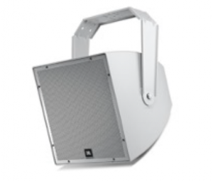 AWC129 SPEAKER
CONTROL 200 MEDIUM-FORMAT CEILING SPEAKERS
We used the same Control 300 Series topology for the Control 200 Series medium-format ceiling speakers – i.e., milling the center of woofer’s pole piece to form the throat and usingthe cone as the bell of a constant directivity horn and then transitioning to the ceiling baffle. The result is a similar degree of constant directivity coverage
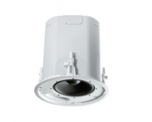
CONTROL 226C/T (WITH BLIND-MOUNT BACKCAN) AND CONTROL 227C/CT (FOR USE WITH PRE-INSTALL BACKCAN)
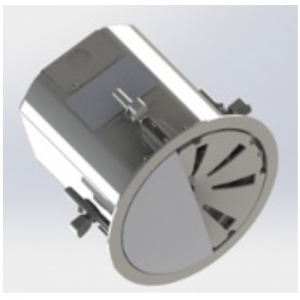
HOW JBL BROUGHT CONSTANT DIRECTIVITY TO CONTROL 40 SERIES CEILING SPEAKERS (AND LATER CONTROL 60 SERIES PENDANT SPEAKERS) USING “CONICAL RBI”
CONTROL 40 SERIES CONSTANT DIRECTIVITY SMALL-FORMAT CEILING SPEAKERS VIA THE CONICAL RBI
The Control 40 Series premium small-format ceiling speakers utilize smaller diameter voice coils on the woofers (compared to Control 300, 200, and AWC Series drivers), resulting in smaller pole pieces that are not big enough to mill out properly for the co-axial constant directivity horns (at least not for achieving the desired wide-coverage angles). So instead,we adapted the RBI Radiation Boundary Integrator that was originally developed for JBL’s VerTec™ and VTX™ tour-sound line array systems. For Control 40 Series, we developed it into the “Conical RBI”.The speaker is constructed with two baffles instead of the usual ceiling speaker’s single baffle. The woofer is mounted on the rear baffle. The tweeter is mounted on the front baffle. The front baffle extends the entire width of the speaker, providing an extremely large and effective waveguide for controlling the coverage of the tweeter down to its lowest frequencies. Then
CONTROL 45C/T (SHOWN WITH AND WITHOUT INCLUDED GRILLE
there are apertures (shaped holes) in the front baffle through which the woofer’s sound projects.About the RBI’s apertures, note that physics dictates a direct mathematical relationship between the diameter of any woofer (called the “piston size” in engineering terminology) and the coverage pattern emanating from the woofer at each frequency. A woofer on a baffle is not a constant directivity device. Each driver follows a certain coverage versus frequency formula, and a larger diameter woofer starts to narrow its coverage at a lower frequency than a smaller diameter woofer does. So, for example, an 8-inch driver starts narrow at a lower frequency than a 5-inch driver does. These are basic laws of physics.
CONTROL 47C/T BEAMWIDTH CHART, SHOWING CONSTANT DIRECTIVITY COVERAGE FROM 1.5 KHZ THROUGH 10 KHZ. COVERAGE SPECIFIED AS BEING 120° (INDICATED BY RED LINE)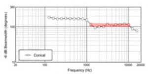
However, with the conical RBI, we can make the speaker act as if it has a different diameter woofer from the size it really has, thus shifting its coverage-by-frequency equation. The apertures make the sound behave as if it is coming from a different diameter woofer (“piston” size), and therefore it exhibits a different coverage than a woofer of its actual size would normally exhibit. We are able to set the design to match the coverage angle at the upper end of the woofer’s frequency range with the coverage angle at the lower end of the tweeter frequency range. This avoids the abrupt transition in coverage angle that is common in ceiling speakers and extends a consistent coverage angle throughout a much broader frequency band. More details about the specific of the Conical RBI design – including about how it had to utilize advanced compression driver design technology to determine factors such as the number of apertures – can be found in the Appendix.
NARROW-COVERAGE CONSTANT DIRECTIVITY CEILING SPEAKER (CONTROL 47HC)Changing the high frequency horn to a substantially narrower coverage and changing the apertures resulted in a constant directivity, source-coherent, narrow coverage model.
CONTROL 47HC NARROW-COVERAGE CONSTANT-DIRECTIVITY CEILING SPEAKER (SHOWN WITH INCLUDED GRILLE REMOVED)
WHY IS A NARROW COVERAGE MODEL NEEDED?
Narrow coverage is especially important for rooms with high ceilings. Listeners in a high-ceiling room should primarily be listening to the speaker that’s above their head and not also to all the other speakers in the room, hitting their ears at different time syncs. Hearing too many speakers simultaneously smears the time arrivals and contributes unnecessarily to excessive reverberation in the room, resulting in muddy music andpoor speech intelligibility. A well-controlled, narrow coverage speaker reduces time smearing, reduces the reverberation in the room (by not splattering the sound all over the place),thus clarifying the quality of music and improving intelligibility of speech. In addition, a well-controlled constant directivity coverage speaker tends to provide a more consistent “power response” – the sum of the total sound emitted into the room in any direction. This gives a more similar sound character to whatever reverberant field there is, tending to make it more similar to the character of the direct sound, thus making it less objectionable. While this makes the Control 47HC a deep speaker in the ceiling, narrow coverage speakers can be used in any application where focused coverage is desired
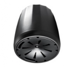
CONTROL 60 CONSTANT DIRECTIVITY HANGING PENDANT SPEAKERS
The same Control 40 Series dual-baffle Conical RBI design has more recently been applied to the Control 60 Series Pendant Speakers. The Control 47C/T design was applied to the Control 67P/T; Control 47HC design was applied to the Control 67HC; Control 45C/T design was applied to theControl 65P/T. All these models utilize the Conical RBI design to achieve constant directivity coverage over a significant frequency range.
CONTROL 67P/T CONSTANT-DIRECTIVITY PENDANT SPEAKER (SHOWN WITH INCLUDED GRILLE REMOVED)
PATTERN CONTROL VERSUS SIZE OF PATTERN CONTROL DEVICE
Why does coverage become wide at lower frequencies? Even constant directivity devices start losing pattern control at low frequencies where the wavelengths are substantially longer than the size of the pattern control device. Each device has a “frequency range of control”, a range within which the device is constant directivity. A speaker that provides very consistent coverage from the highest audio frequencies down through the frequency-control limit based on the size of the device provides as much pattern control as a device of its size can provide. Below that, it’s important to transition smoothly to the omnidirectional dispersion that naturally occurs at low frequencies.
CONSTANT DIRECTIVITY CEILING SPEAKERS:
- Control 40 Series: Control 45C/T, Control 47C/T, Control 47LP, Control 47HC/T – True co-axial, source-coherent, constant
- Control 200 Series: Control 226CT, Control 227C, Control 227CT – True co-axial, source-coherent, constant
- Control 300 Series: Control 328C & CT, Control 321C & 321CT, Control 322C & CT – True co-axial, source- coherent, constant
CONSTANT DIRECTIVITY PENDANT SPEAKERS:
- Control 60 Series: Control 65P/T, Control 67P/T, Control 67HC/T – True co-axial, source-coherent, constant directivity.
DIRECTIVITY CONTROL IN OTHER JBL PROFESSIONAL LOUDSPEAKER LINES ■
Of course, JBL applies as much directivity control as we can to most of our products in one way or another. The EON 600 line, for example, utilizes a unique pattern control aperture in front of the woofers in the 12” and 15” models to make their off-axis coverage more consistent than these drivers would otherwise be on their own

ACOUSTIC LOADING APERTURE OVER EON 600 LF DRIVER IMPROVES DIRECTIVITY (SHOWN WITH INCLUDED GRILLE REMOVED)
JBL CBT Series Constant Beamwidth Technology columns combine constant directivity with the narrow vertical coverage that’s needed to cover audience areas.JBL’s Intellivox column speakers allows very precise, adjustable complex room-mapping coverage via built-in individual DSP channels on each driver
CBT 1000 WITH CBT 1000E (2 METERS TALL) AND INTELLIVOX DS280HD (2.8 METERS TALL) UTILIZE HEIGHT (ALONG WITH ADVANCED PATTERN-CONTROL ALGORITHMS) TO ACHIEVE CONSISTENT VERTICAL PATTERN CONTROL TO VERY LOW FREQUENCIES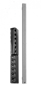
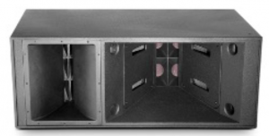
JBL’s VTX touring systems are built around providing proper directivity control for the venue.The massive VLAi, as well as PD and AE loudspeakers – as more examples – provide well-controlled, defined coverage patterns to fit a wide variety of different applications and coverage requirements.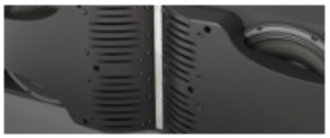
VTX A SERIES RBI (RADIATION BOUNDARY INTEGRATOR) ACOUSTICALLY INTEGRATES MIDS AND HIGHS, AND THE LF ACOUSTIC LOADING APERTURE AND OTHER DESIGN FEATURES CONTRIBUTE TO EXCELLENT OVERALL COVERAGE CONTROL TO MATCH THE REQUIREMENTS OF EACH VENUE. (SHOWN WITH INCLUDED GRILLE REMOVED.)
VLA-601I WITH VERY LARGE MF AND HF HORNS FOR CONSISTENT PATTERN CONTROL. (SHOWN WITH INCLUDED GRILLE REMOVED.)
The better the directivity control, the greater the consistency of the sound character will be throughout the listening area. There will be less excitation of the reverberant field, and the sonic quality of music and the intelligibility of speech will be greatly improved. This paper focuses on how JBL brought Constant Directivity to the Control 40 Series via the conical RBI. The products mentioned in this paper are just some of the examples of how JBL has brought superb degrees of directivity control to our product lines
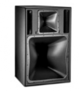
PD6322/64 WITH MF (24” X 24”) AND HF HORNS (12” X 12”) THAT ARE SIZED FOR EXCELLENT CONTROL OF THEIR FREQUENCY BANDS. (SHOWN WITH INCLUDED GRILLE REMOVED.)
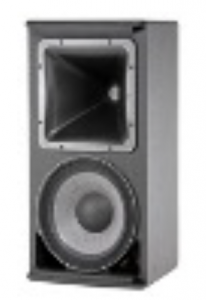
AM7212/95 WITH HF HORN (12” X 12”) THAT IS SIZED FOR EXCELLENT CONTROL OF ITS FREQUENCY BAND. (SHOWN WITH INCLUDED GRILLE REMOVED.)
AppendixENGINEERING DESIGN OF THE CONTROL 40 SERIES CONSTANT DIRECTIVITY CEILING SPEAKERS ■
It is possible to make cost effective, full range systems using a single small-diameter, carefully designed driver. However, reaching high SPL with low distortion generally requires more than one driver to cover the entire audio frequency range. In applications where very uniform dispersion is needed in all directions, mounting drivers co-axially has clear advantages since the radiation pattern has perfect symmetry at all listening angles, in addition to compact size.
The most common implementation of a coaxially mounted woofer and tweeter has simply been to mount a tweeter in front of a woofer, either suspended or on a post. This low-cost approach, while simple, suffers from poor directivity matching between the drivers and leads to choppy frequency response both on and off-axis due to reflections off the woofer cone.JBL Professional’s engineering team sought to develop a solution for small-format ceiling speakers which takes maximum advantage of the coaxial concept with its promise of compact size to achieve seamless transition between drivers, along with an ultra-uniform, constant-directivity, wide-angle dispersion. Inspired by JBL’s flagship VERTEC line array technology, the design team’s work resulted in an elegant solution which was given the inside-the-company name of ORBITM (Omnidirectional Radiation Boundary Integrator). The result of extensive acoustical simulations and optimization, this patent-pending solution made its debut in the Control 40 series ceiling speakers and was later also implemented in the Control 60 Series of pendant speakers
HORN DESIGN
The directivity of a cone driver or a dome tweeter radiating into free space is not constant; it is determined by the size of the radiator and is very frequency dependent, becoming more directional with increasing frequency. Applications where uniform dispersion is desired are a natural fit for horn/ waveguide loading, which can control the directivity so that the tonal balance is maintained regardless of whether the listener is on or off-axis. This is the goal of Constant Directivity “CD”
horns. Designing horns that have constant directivity and the desired coverage angle at all frequencies is not a trivial task. Traditionally, these types of horns have been designed in an iterative fashion, using approximate design rules to get close, making a physical prototype, and then making small changes to the prototype to steer the performance in the desired direction, resulting in a new physical prototype to measure. This procedure of “cut and try” is repeated many times and eventually leads to a horn with performance relatively close to the desired goal, however it is a laborious, expensive, and time consuming process.For the Control 40 project, JBL used the concept of “virtual prototyping” to design the waveguide shape, creating most of the prototypes in the computer and performing virtual acoustic measurements through the use of finite element modeling.Using this method, the complete performance of a given horn shape could be simulated quickly using only a CAD model and acoustic simulation software. This ability allowed dozens of iterations to be evaluated in rapid succession, leading to a prediction for the optimized horn profile. In the end, an optimized horn shape was physically prototyped and found to exhibit the desired performance and a close match to the simulation.
FIGURE 1 SIMULATED VS. MEASURED BEAMWIDTH FOR 65 DEGREE WAVEGUIDE
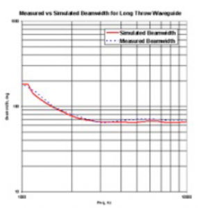
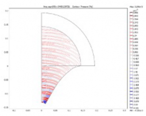
FIGURE 2 ACOUSTICAL SIMULATION OF 65 DEGREE WAVEGUIDE SHOWING WAVEFRONTS AT 10KHZ
Narrow coverage is especially important for rooms with high ceilings. Listeners in a high-ceiling room should primarily be listening to the speaker that’s above their head and not also to all the other speakers in the room, hitting their ears at different time syncs. Hearing too many speakers simultaneously smears the time arrivals and contributes unnecessarily to excessive reverberation in the room, resulting in muddy music and poor speech intelligibility. A well-controlled, narrow coverage speaker reduces time smearing, reduces the reverberation in the room (by not splattering the sound all over the place), thus clarifying the quality of music and improving intelligibility of speech. In addition, a well-controlled constant directivity coverage speaker tends to provide a more consistent “power response” – the sum of the total sound emitted into the room in any direction. This gives a more similar sound character to whatever reverberant field there is, tending to make it more similar to the character of the direct sound, thus making it less objectionable. While this makes the Control 47HC a deep speaker in the ceiling, narrow coverage speakers can be used in any application where focused coverage is desired
DEVELOPMENT OF THE ORBI™ (INSIDE-THE-COMPANY NAME) OMNI-DIRECTION RADIATION BOUNDARY INTEGRATORThe challenge of effectively integrating the output of the waveguide-mounted tweeter with that of the woofer mountedbehind it has been faced by many system designers. Other manufacturers have tried various means to accomplish this, including placing a perforated horn in front of the woofer, as.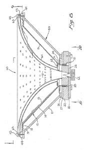
FIGURE 3 1986 PATENT SHOWING CONCEPT OF PERFORATED WAVEGUIDE
shown in this 1986 patent #4619342Others have simply tried to restrict the woofer energy by placing it on a horn, making little attempt to control the tweeter radiation. Neither of these solutions is ideal from a dispersion standpoint, and both still require the use of an electronic crossover for both the woofer and the tweeter.A more elegant solution would be to use the concept of acoustic filtering to low-pass the woofer, while using the same structure as the waveguide for the tweeter. From their extensive history with the development of compression drivers, JBL designers realized that the same physics that determine the acoustic behavior of traditional compression driver phaseplugs could be applied to the problem at hand. To understand how this came about, let us now take a brief detour and discuss some aspects of phaseplug design in compression drivers
A NEW APPLICATION FOR COMPRESSION DRIVER THEORY
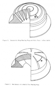
The well-known “concentric ring” phaseplug used almost universally in pro sound compression drivers is a structure that serves two primary purposes – the first is to provide compression loading for the diaphragm (which increases its efficiency), and the second is to equalize the path length.
of the pressure created by the vibrating diaphragm so that a uniform wavefront is created at the entrance to the horn. While quite complex in theory to design properly,one macroscopic feature that must be determined up front is how many slots the phaseplug will have. This decision affects the theoretical high frequency limit of the driver – generally more slots are required to have acoustic output at higher frequencies because of a natural acoustic filtering determined by the distance between each slot, which sets a high frequency limit. Less expensive drivers, or those that have no need to reach the highest octaves may be designed with perhaps 2 slots, while compression drivers designed for full bandwidth operation are commonly seen with 3, 4 or even 5 annular slots. Alternatively, phaseplugs can be designed radial slots instead of annual ring slots. Radial slot phaseplugs work in much the same way as their concentric ring brethren, except that the high frequency limit is set by the angular distance between the slots rather than the radial distance, marked “W” in the figures below.
Another design parameter that affects performance in a compression driver is the spacing between the vibrating diaphragm and the adjacent phaseplug surface. Generally the smaller the air gap between the phaseplug and the diaphragm, the more high frequency output the driver will have. Of course there is a limit to how closely the phaseplug and diaphragm can be placed, since the diaphragm must have enough room to vibrate freely without hitting the stationary phaseplug.Mathematical models showing the effect of these macroscopic variables such as number of slots and spacing to the diaphragm were developed many years ago, allowing designers to predict their effect.
Usually, an engineer designing a phaseplug would strive to maximize the output at high frequencies and therefore use as many slots and as close diaphragm spacing as practical. However, there is nothing to prevent a designer from purposely designing a “poor” phaseplug that has a very low high-frequency limit if he desires to use it as an acoustic low pass filter.Following this line of thought, and considering the woofer cone as the diaphragm of a compression driver, JBL engineers realized that by covering the woofer with a structure that looks somewhat like a radial slot phaseplug, with the proper slot spacing, and placed at just the right distance from the cone, an acoustic filter could be created that would only allow low frequencies to pass through it, and effectively behave as an acoustic crossover for the woofer.
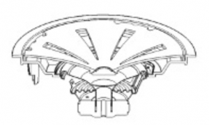
FIGURE 9 WIDE DISPERSION ORBI ON WOOFER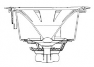
FIGURE 10 LONG THROW ORBI ON WOOFER
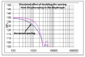
The graph below shows the measured effect of adjusting the spacing between the woofer and the ORBI by 6mm. As predicted by the simulation, increasing the spacing starts to roll off the woofer at a lower frequency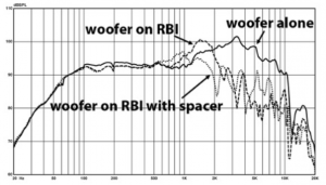
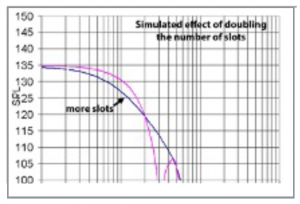
The graph below shows the measured effect of changing the number of openings, which effectively is the same as changing the spacing between them (factor “W”) from the simulation above. Clearly, the larger the distance between the slots, the lower the acoustic crossover frequency is. The reduced output apparent below 600Hz is due to insufficient open area in this particular experimental version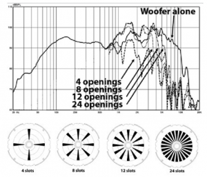
By increasing the amount of open area to allow more woofer output to pass through the ORBI, but still keeping only 4 openings, it is possible to create the response below, which also shows the woofer by itself for comparison. Clearly the ORBI is acting as an effective low-pass filter which could take the place of the usual electrical crossover network.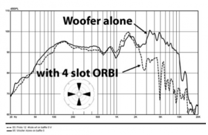
If desired, additional electrical filtering can be applied to the woofer for greater stop-band attenuation, as shown here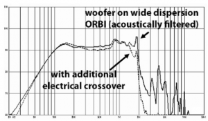
Since this ORBI must act as a proper waveguide for the tweeter, some optimization must be done to the openings size, shape, and position so that the acoustical performance of the tweeter waveguide is maintained. Optimizing these perforations for the best lowpass behavior while maintaining smooth frequency response and dispersion for the tweeter led to a final design which effectively combined both aspects into a single, high value part, with a combined frequency response as shown below: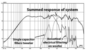
ULTRA-WIDE DISPERSION DESIGN
While designing a horn shape for constant directivity through smaller included angles (less than about 90 degrees) is straightforward, it is rare to see a horn that has very wide dispersion of greater than 100 degrees while maintaining constant directivity. The reason for this is that applying the usual design rules to very wide dispersion designs results in poor loading at lower frequencies.In general, a tweeter mounted in an infinite baffle will tend to have very wide dispersion at mid frequencies and narrowing dispersion (beaming) at higher frequencies. Opening the design space to all possible horn shapes through the use of acoustic simulations and optimization, it is possible to design a waveguide profile which allows the tweeter to have broader and more consistent coverage than the same tweeter mounted in a pure half space. Combining this waveguide with a coaxial woofer and ORBI slot-loading results in a speaker system with smooth directivity and extremely wide dispersion
Engineering Design Section Credit: Alex Salvatti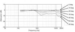 FIGURE 5 NORMALIZED OFF AXIS FREQUENCY RESPONSE FAMILY OF 47C SYSTEM
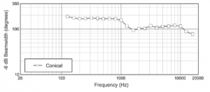 FIGURE 6 BEAMWIDTH OF 47C SYSTEM APPROACHES 120 DEGREES OVER A WIDE FREQUENCY RANGE
Read More About This Manual & Download PDF:
References
[xyz-ips snippet=”download-snippet”]