
JBL LS360C Manual

THANK YOU FOR CHOOSING JBL
For more than 60 years, JBL has been involved in every aspect of music and film recording and reproduction, from live performances to the recordings you play in your home, car or office.
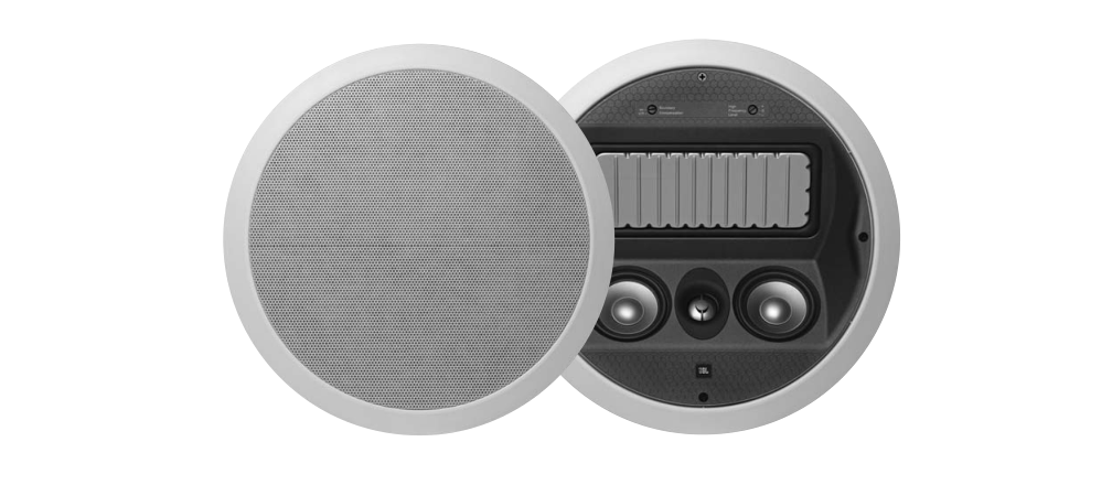
The LS360C has been specifically designed to deliver unsurpassed home theater sound reproduction from an in-ceiling speaker that does not intrude on your room or its décor.
Please take a moment to register your product on our Web site at www.jbl.com. It enables us to keep you posted on our latest advancements, and helps us to better understand our customers and build products that meet their needs and expectations.
UNPACKING THE SPEAKERS
Carefully unpack the speakers. If you suspect damage from transit, report it immediately to your dealer and/or delivery service. Keep the shipping carton and packing materials for future use. All models include a mounting template and paint shield.
PLANNING YOUR SYSTEM
NOTE: A JBL powered subwoofer will add impact and realism to both music and film soundtracks. Contact your JBL dealer for recommendations on subwoofer models for your application.
PLACEMENT
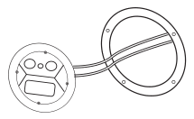
NOTE: In all applications, the tweeter and dual midrange drivers should be aimed toward the listening area.
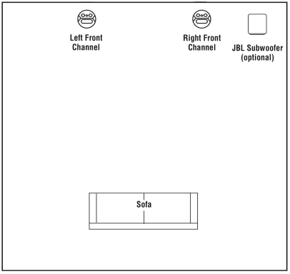
STEREO
Before deciding where to place your speakers, survey your room and think about placement, keeping the following points in mind, and using Figure 1, on previous page, as a guide:
- For best results, place the speakers 6’–8′ apart.
- Refer to “Home Theater” below if you also plan to use the speakers in a home theater system.
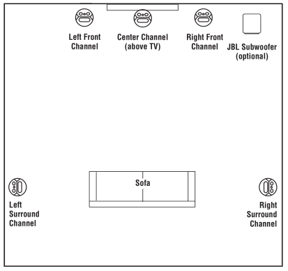
HOME THEATER
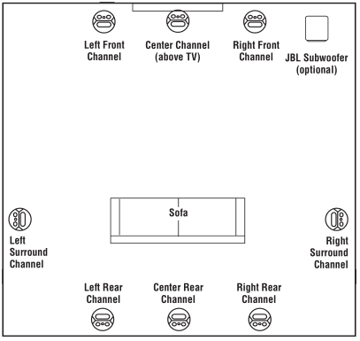
For front-channel use, place one speaker on the left and another on the right along either side of the television. A center channel speaker should go directly above the television. For left and right surround channels, place one speaker on the left and another on the right, to the side of or slightly behind the listening area. In 6- or 7-channel configurations, place the rear channel(s) behind the listening position, as shown in Figure 3.
NOTE: A JBL powered subwoofer will add impact and realism to both music and film soundtracks. Contact your JBL dealer for recommendations on subwoofer models for your application. Proper placement of the speakers is an important step in obtaining the most realistic soundstage possible. These recommendations are for the optimal placement of the loudspeakers. Use these placement recommendations as a guide. Slight variations will not diminish your listening pleasure.
INSTALLATION
NOTE: The LS360C in-ceiling speaker was designed to be easily installed. However, if you are unable to clearly and fully understand and follow the instructions in this manual, or if you are unsure of your ability to properly install these loudspeakers, please contact your dealer or a qualified installer.
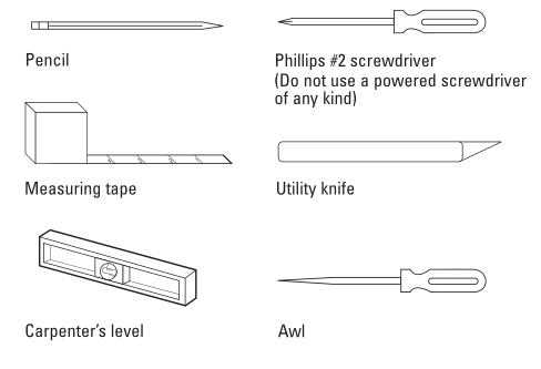
TOOLS NEEDED
SPEAKER CONNECTIONS
CONNECTION TIPS
Wire Length Recommended SizeUp to 100 ft. 16-gaugeGreater than 100 ft. 12-gauge
TURN OFF ALL POWER
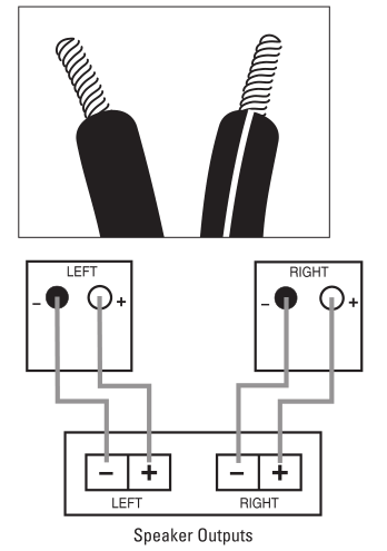
Before completing the installation, you must connect your speakers to your system. First, turn off all audio-system power. Use high-quality speaker wire to make your connections. Use at least #16-gauge speaker wire with polarity coding. Heavier-gauge wire is recommended for larger distances. Consult the chart above or your dealer for recommendations. The side of the wire with a ridge or other coding is usually considered positive (+) polarity. Also, consult the owner’s manuals that were included with your amplifier or receiver to confirm connection procedures.
Observe polarities when making speaker connections, as shown in Figure 4. Connect each + terminal on the back of the amplifier or receiver to the respective + (red) terminal on each speaker. Connect the – (black) terminals in the same way.
IMPORTANT!Do not reverse polarities (i.e., + to – , or – to +) when making connections. Doing so will cause poor imaging and diminished bass response. Be certain that positive and negative wire strands are completely isolated to avoid short circuits that may damage your equipment.
EXISTING CONSTRUCTION
- Remove the plastic paint shield from the speaker frame.

- Determine the correct speaker location. NOTE: Use the included template when cutting the drywall.
- NOTE: Always allow at least a 1/2 inch between a ceiling stud/joist and the speaker cutout, or the locking tabs will not be able to swivel into place.
- Ensure that the drywall or plywood board or other appropriate wallboard is at least a 1/2-inch thick, and confirm that the board material is capable of withstanding the weight of the speaker you will be installing. Cut the drywall.
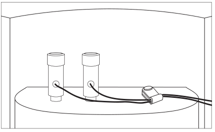
- Connect the speaker wires to the speaker. It is recommended that the nylon cable-strain relief tab, located next to the speaker terminals, be used to help prevent the speaker wires from being accidentally dislodged (see Figure 5, below).
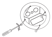
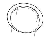
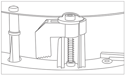
- Make sure all four locking tabs are properly positioned against the locking tab stops that are located on the speaker frame (see Figure 6, below). After confirming this, carefully place the frame assembly in the ceiling and confirm that there is no more than 1/8-inch play between the frame and the ceiling cutout. After positioning the speaker in the mounting location, back each screw out one full turn (turn counterclockwise).
- Screw down each of the four Phillips-head screws, alternating between the four screws. The locking tabs will swivel into place and secure the unit to the rear surface of the ceiling. Hand-tighten with a nonpowered, straight-handle regular screw-driver only. Do not use a socket wrench, a powered screwdriver, a drill or any other powered tool. Confirm that the speaker is firmly and securely held in place and that all four locking tabs are firmly resting against the ceiling.
- Attach the metal grille and logo, if desired.

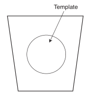 NOTE: Use the included template when cutting the drywall.
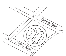


NEW CONSTRUCTION
If you wish to preinstall a rough-in frame before the drywall is installed, you will need to purchase the RIF10C rough-in-frame. Detailed installation instructions are supplied with the rough-in kit.
PAINTING THE SPEAKER FRAME AND GRILLE
The LS360C in-ceiling loudspeaker can be painted to match any décor. If you wish to change the color, the satin finish on the grille and frame will function as a primer coat. Before painting, install the paint shield (inner section of template in the assembly kit) securely into the recess in the baffle. This will protect the speaker components and baffle from paint residue. Use a high-quality spray paint, and apply a thin coat of color. Be certain the grille perforations remain free of paint. Filling them with paint will diminish the sound quality.
NOTE: Gently remove the acoustical foam blanket from the grille before painting. Reattach the blanket after the paint has dried.
OPERATION
SURROUND SETTINGS
When using the system in a Dolby ® Digital or DTS ® home theater system, make sure all speakers are set to “Small.” Some Dolby Digital-equipped receivers/processors offer different setup options for each source or surround mode: e.g., CD-stereo, videotape, Dolby or Pro Logic ® . In each case, follow your equipment’s instructions to ensure that the subwoofer (if you have one) output is turned on and that the speakers are set to “Small” in each mode.
TWEETER-LEVEL CONTROL
In most typical listening rooms, this switch should be left in the neutral or “0” position. This setting will deliver the most neutral and balanced sound. In some extreme cases, it may be desirable to slightly boost or cut the tweeter’s output, depending upon the room layout, construction and furnishings.
If the room is sparsely furnished, contains large exposed windows or is otherwise very reverberant, you may want to set the control to the “–” (–1.5dB) position. If the room is exceptionally absorbent because it is well furnished or has thick curtains and/or carpet, you may want to increase the tweeter output by setting this switch to the “+” position (+1.5dB). Of course, the control may be set to either position, based on listener preference.
BOUNDARY COMPENSATION CONTROL
This control is designed to be engaged when positioning the loudspeaker within two feet of another surface to eliminate the bass peak caused by the second surface and to maintain a smooth, natural bass response. For example, if you need to install your in-ceiling speaker within two feet of a side wall or corner, it is recommended that the Boundary Compensation control be set to the “On” position. In all other installations, the control should typically be set to “Off”. Of course, the control may be set to either position, based on listener preference.
SPECIFICATIONS
Frequency Range : ( + – 3dB) 80Hz – 20kHzRecommended Amplifier Power Range : 10 – 200 WattsSensitivity (2.83V @ 1 meter) : 85dBNominal Impedance : 8 OhmsCrossover Frequency : 700Hz, 2,000Hz; 24dB/octaveLow-Frequency Driver : 7-3/4″ x 3-3/8″ (197mm x 85mm) Radiator Plus ™Midrange Drivers : Dual 3″ (75mm)High-Frequency Driver : 1″ (25mm) Pure titaniumExternal Diameter (W x H) : Diameter: 12-3/4″ (323mm)Mounting Cutout Diameter (W x H) : Diameter: 11-3/8″ (289mm)Mounting Depth : 5-5/8″ (142mm)Weight (Net) : 8 lb (3.6kg)
Features, specifications and appearance are subject to change without notice.
JBL is a trademark of Harman International Industries, Incorporated, registered in the United States and/or other countries. Pro Sound Comes Home, Studio and Radiator Plus (patent pending) are trademarks of Harman International Industries, Incorporated.
Dolby and Pro Logic are registered trademarks of Dolby Laboratories.
DTS is a registered trademark of DTS, Inc.

JBL LS360C Manual – JBL LS360C Manual –