LiveLink 4 – 728/J8518Technical ManualIssue 1.020 January 2021DOCUMENT SECURITY CLASSIFICATIONPublicNo existing release restrictions other than normal non-disclosure rules
Overview
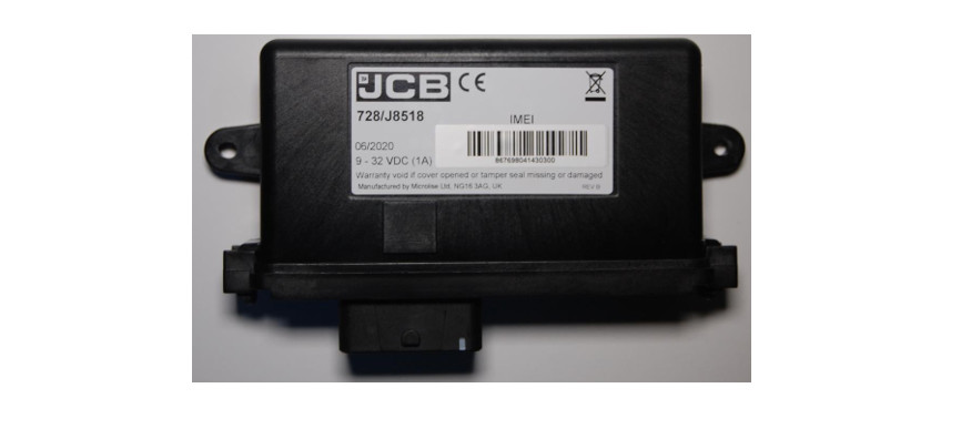
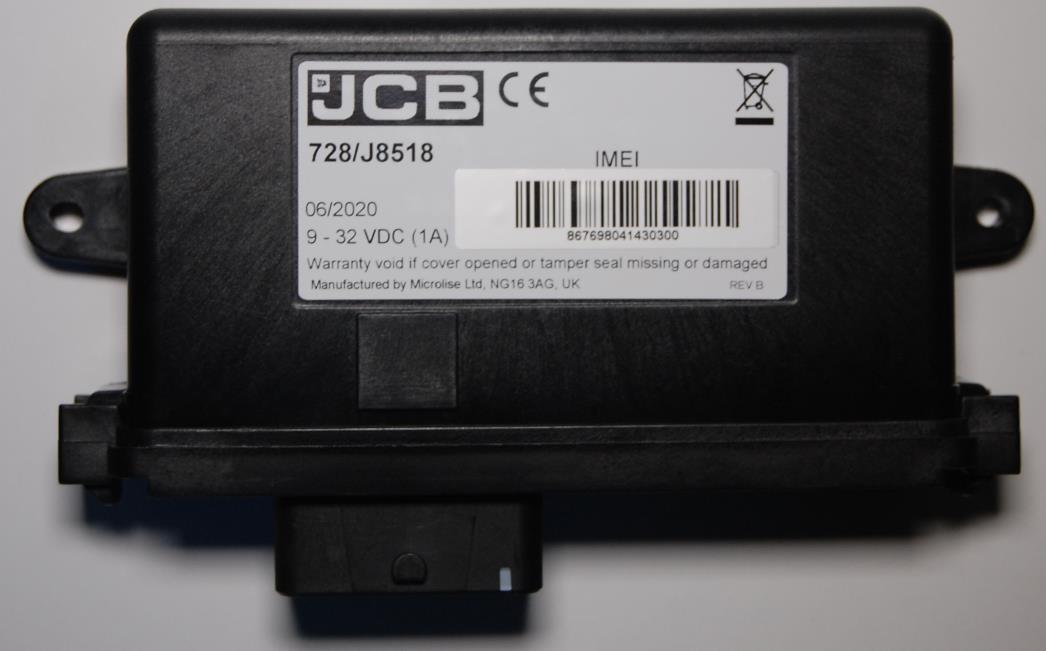
The LiveLink 4 is a battery-backed vehicle tracking and telematics unit utilizing GPS, GSM / GPRS, BLE, and Wi-Fi technology.
Installation
LiveLink 4 units are designed to be installed both within the vehicle cab in a protected environment and externally fitted.Depending on the application the device may be permanently powered, or only powered periodically. In either application, the LiveLink 4 is designed to make efficient use of the power available through the use of sleep modes when there is no activity.
When selecting a suitable mounting location, please be aware of:
- Excessive temperatures
- Corrosive fluids
- Areas where the unit may obstruct the driver’s view or impede the operation of the vehicle
- Locations that may shield the unit affecting GPS and/or GPRS reception.
- Unit and antenna separation distance of at least 20cm from all persons, animals, and other antennae or transmitters.
- Local or international regulations regarding the fitment of equipment within vehicles.
The installation must be carried out following FCS1362:2010 or later, by a Microlise approved installer. The recommend installation to vehicles is to be mounted on 2 x M5 fixings, tightened to 2Nm.For installation, the unit must be fused on the power input at 2A, and on the ignition input at 1A using automotive fuses and fuse holders tested to relevant safety standards appropriate for the intended country of use.The minimum connections to the vehicle for unit operation are listed below.
| Connection | Pin Number | Fused |
| Power | 4M | Yes – 2A |
| Ignition | 2M | Yes – 1A |
| Ground | 3M | No |
| Ignition Ground | 2L | No |
Refer to relevant product guidelines and vehicle surveys for installation specifics.
Description of operation
Providing external power is applied, or the internal battery is sufficiently charged, and the unit is within GPS and GPRS coverage the unit will periodically (based on time and/or distance, and configuration) transmit location and telematics information to the relevant Microlise system.
If out of GPRS coverage then messages are stored into non-volatile Flash memory for transmission later when a GPRS connection can be established.
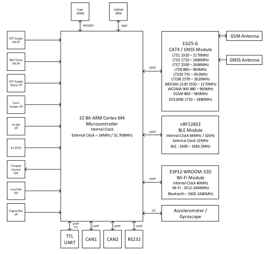
Whilst operating on external power the unit will charge the internal battery as required.Two CAN interfaces are incorporated which are typically used to either listen for or request information on automotive CAN busses.The unit incorporates an RS232 interface which can be used for connection of a variety of peripherals, e.g. Mobile Data Terminals, refrigeration temperature monitoring equipment, printers, sensors or other devices.The unit incorporates six digital inputs. One is available for monitoring ignition status, another for engine run, the remainder are general-purpose inputs that can be used for monitoring doors switches, panic buttons or other digital signals.A real-time clock is incorporated for time-stamping all events recorded by the unit.The unit monitors its internal temperature. Battery charging is only permitted when the temperature is within the specified limits of the battery pack.The Bluetooth interface can be used for diagnostics or connection to peripheral devices, e.g. a data terminal.A Bluetooth Low Energy interface is available for monitoring a variety of BLE devices and tags.The unit is fitted with internal GSM, GPS, Bluetooth and Wi-Fi antennas.The built-in accelerometer can be used to monitor harsh braking, acceleration, cornering, and any lean of the vehicle.The built-in modem supports four GSM frequency bands, seven UMTS frequency bands, and nineteen LTE frequency bands (see Technical Specification section for details).The LiveLink 4 supports the application of firmware and configuration to allow specific user and vehicle profiles and functionality. These are applied by Microlise only and are not accessible to the end-user. The firmware and configuration do not affect the performance of the integrated RF modules, and changes to firmware and configuration do not affect the approval compliance of the product.
Service / Repair
The LiveLink 4 contains no user tuneable or serviceable parts. Service of the LiveLink 4 should only be carried out by authorized personnel.Technical queries should be directed to Microlise as the manufacturer at the address below:Microlise LtdFarrington WayEastwoodNG16 3AGUnited Kingdom
Block Diagram

Technical Specification
| Item | Specification |
| Power Supply: | 9 – 32 V dc, or internal 3.7V Li-ion battery |
| Current Consumption: | 1A Max, <2mA average in sleep mode |
| Supported interfaces: | RS232 x 1Engine runIgnitionIsolated ignitionAnalog / digital inputs x 4CAN bus interface x 2BLEAccelerometer3V nano SIM card interface |
| GSM/UMTS/LTEBands Supported:GPRS:Frequency:Max Power Output: | LTE 1, 2, 3, 4, 5, 7, 8, 12, 13, 18, 19, 20, 25, 26, 28, 38, 39, 40, 41UMTS 1, 2, 4, 5, 6, 8, 19GSM 850, 900, 1800, 1900703 – 2690MHzSee Cellular RF Power Output Table |
| Internal GSM AntennaModel:Frequencies:Peak Gain: | Taoglas PCS.06.F698 – 960MHz, 1710 – 2690MHz3.72dBi (2500 – 29690MHz) |
| GNSSReceiver: | Supports GPS, GLONASS, BeiDou, Galileo |
| Internal GPS AntennaModel: | Abracon GPS + GLONASS Patch Antenna |
| BLEClass:Frequencies:Power Output: | 5.12400 – 2483.5MHz8dBm Max |
| Wi-FiProtocol:Frequencies:Power Output: | 2.4GHz 802.11b/g/n2400 – 2483.5MHz+20dBm (802.11b) |
| BluetoothClass:Frequencies:Power Output: | 5.12402 – 2480MHz+8.61dBm |
| MechanicalDimensions:Weight: | 180mm x 40mm x 115mm400g |
| EnvironmentalOperating Temperature:Storage Temperature:IP rating: | -20°C – +70°C-40°C – +85°CIP69K |
1.1 Cellular RF Power Output
| Technology | Band | Max Output Power | TX Freq |
| LTE | 1 | 25dBm | 1920 – 1980 |
| LTE | 2 | 25dBm | 1850 – 1910 |
| LTE | 3 | 25dBm | 1710 – 1785 |
| LTE | 4 | 25dBm | 1710 – 1755 |
| LTE | 5 | 25dBm | 824 – 849 |
| LTE | 7 | 25dBm | 2500 – 2570 |
| LTE | 8 | 25dBm | 880 – 915 |
| LTE | 12 | 25dBm | 699 – 716 |
| LTE | 13 | 25dBm | 777 – 787 |
| LTE | 18 | 25dBm | 815 – 830 |
| LTE | 19 | 25dBm | 830 – 845 |
| LTE | 20 | 25dBm | 832 – 862 |
| LTE | 25 | 25dBm | 1850 – 1915 |
| LTE | 26 | 25dBm | 814 – 849 |
| LTE | 28 | 25dBm | 703 – 748 |
| LTE | 38 | 25dBm | 2570 – 2620 |
| LTE | 39 | 25dBm | 1880 – 1920 |
| LTE | 40 | 25dBm | 2400 – 2400 |
| LTE | 41 | 25dBm | 2496 – 2690 |
| UMTS | 1 | 25dBm | 1920 – 1980 |
| UMTS | 2 | 25dBm | 1850 – 1910 |
| UMTS | 4 | 25dBm | 1710 – 1755 |
| UMTS | 5 | 25dBm | 824 – 849 |
| UMTS | 6 | 25dBm | 830 – 840 |
| UMTS | 8 | 25dBm | 880 – 915 |
| UMTS | 19 | 25dBm | 830 – 845 |
| GSM | 850 | 35dBm | 824 – 849 |
| GSM | 900 | 35dBm | 880 – 915 |
| GSM | 1800 | 35dBm | 1710 – 1785 |
Regulatory and Type Approvals
1.1 CEEU DECLARATION OF CONFORMITY
We,Microlise LtdOf: Famington Way, Eastwood, Nottingham, NG16 3AG, United KingdomDeclare that the declaration is issued under our sole responsibility and belongs to the following product:
Product: LiveLink 4Type: 728/J8518
The object of the declaration described above is in conformity with the relevant Union harmonization legislation:
Radio Equipment Directive 2014/53/EU
Restriction on Hazardous Substances 2011/65/EU
The following harmonized standards or technical specifications have been applied:
Radio Equipment Directive 2014/53/EU
Health (Article 3.1(a)):EN62311:2020EN62368-1:2014EN 301 489-1 V2.2.3 (2019-11)EN 301 489-17 V3.2.2 (2017-12)EN 301 489-19 V2.1.1 (2019-04)EN 301 489-52 V1.1.0 (2016-11)Spectrum (Article 3.2) EN 300 328 V2.2.2 (2019-07)EN 301 511-13 V12.5.1 (2017-03)EN 301 908-2 V11.1.2 (2017-08)EN 301 908-13 V11.1.2 (2017-07)EN 303 413 V1.1.1 (2017-06)
Notified Body: Element Material Technologies
4 Digit Notified Body Number: 0981Reference Number of Certificate: ENW2ORED1 075Intervention of Notified Body: EU-Type Examination for Article 12Signed for and on behalf of:
 Ian Dickinson, Director of Hardware DevelopmentMicrolise Ltd, 12 January 2021
1.2 E-Mark
| Product | E-Mark Status |
| LiveLink 4 | E Marked – E11 10R-05 11336A copy of the product approval certificate is available on request. |
1.3 Global Approvals
1.3.1 Canada (ISED)
IC ID: 21450-LL4Contains Espressif ESP32-WROOM-32D IC ID: 21098-ESPWROOM32DContains Quectel EG25-G IC ID: 10224A-201903EG25G
This device complies with Industry Canada’s license-exempt RSSs. Operation is subject to the following two conditions:(1) This device may not cause interference; and(2) This device must accept any interference, including interference that may cause undesired operation of the device.
1.3.2 United States (FCC)
FCC ID: OUU-LL4Contains Espressif ESP32-WROOM-32D FCC ID:2AC7Z-ESPWROOM32DContains Quectel EG25-G FCC ID: XMR201903EG25G
FCC warning statement:
- This device complies with Part 15 of the FCC Rules.Operation is subject to the following two conditions:(1) This device may not cause harmful interference, and(2) This device must accept any interference received, including interference that may cause undesired operation.
- This equipment complies with FCC radiation exposure limits set forth for an uncontrolled environment. End-users must follow the specific operating instructions for satisfying RF exposure compliance. This transmitter must not be co-located or operating in conjunction with any other antenna or transmitter.
- Changes or modifications not expressly approved by the party responsible for compliance could void the user’s authority to operate the equipment
Issue History
| Issue | Author | Date | Change Details |
| 1.0 | J Marley | 20/01/21 | Initial Version |
CLASSIFICATION: PUBLICDATE OF PRINT: 20 January 2021
References
[xyz-ips snippet=”download-snippet”]