JET Pneumatic HVLP Spray Gun
Warranty and Service
JET warrants every product it sells against manufacturers’ defects. If one of our tools needs service or repair, please contact Technical Service by calling 1-800-274-6846, 8AM to 5PM CST, Monday through Friday.
Warranty PeriodThe general warranty lasts for the time period specified in the literature included with your product or on the official JET branded website.
- JET products carry a limited warranty which varies in duration based upon the product. (See chart below)
- Accessories carry a limited warranty of one year from the date of receipt.
- Consumable items are defined as expendable parts or accessories expected to become inoperable within a reasonable amount of use and are covered by a 90 day limited warranty against manufacturer’s defects.
Who is CoveredThis warranty covers only the initial purchaser of the product from the date of delivery.What is CoveredThis warranty covers any defects in workmanship or materials subject to the limitations stated below. This warranty does not cover failures due directly or indirectly to misuse, abuse, negligence or accidents, normal wear-and-tear, improper repair, alterations or lack of maintenance. JET woodworking machinery is designed to be used with Wood. Use of these machines in the processing of metal, plastics, or other materials outside recommended guidelines, may void the warranty. The exceptions are acrylics and other natural items that are made specifically for wood turning.
Warranty LimitationsWoodworking products with a Five Year Warranty that are used for commercial or industrial purposes default to a Two Year Warranty. Please contact Technical Service at 1-800-274-6846 for further clarification.
How to Get Technical SupportPlease contact Technical Service by calling 1-800-274-6846. Please note that you will be asked to provide proof of initial purchase when calling. If a product requires further inspection, the Technical Service representative will explain and assist with any additional action needed. JET has Authorized Service Centers located throughout the United States. For the name of an Authorized Service Center in your area call 1-800-274-6846 or use the Service Center Locator on the JET website.
More InformationJET is constantly adding new products. For complete, up-to-date product information, check with your local distributor or visit the JET website.
How State Law AppliesThis warranty gives you specific legal rights, subject to applicable state law.
Limitations on This WarrantyJET LIMITS ALL IMPLIED WARRANTIES TO THE PERIOD OF THE LIMITED WARRANTY FOR EACH PRODUCT. EXCEPT AS STATED HEREIN, ANY IMPLIED WARRANTIES OF MERCHANTABILITY AND FITNESS FOR A PARTICULAR PURPOSE ARE EXCLUDED. SOME STATES DO NOT ALLOW LIMITATIONS ON HOW LONG AN IMPLIED WARRANTY LASTS, SO THE ABOVE LIMITATION MAY NOT APPLY TO YOU. JET SHALL IN NO EVENT BE LIABLE FOR DEATH, INJURIES TO PERSONS OR PROPERTY, OR FOR INCIDENTAL, CONTINGENT, SPECIAL, OR CONSEQUENTIAL DAMAGES ARISING FROM THE USE OF OUR PRODUCTS. SOME STATES DO NOT ALLOW THE EXCLUSION OR LIMITATION OF INCIDENTAL OR CONSEQUENTIAL DAMAGES, SO THE ABOVE LIMITATION OR EXCLUSION MAY NOT APPLY TO YOU.
JET sells through distributors only. The specifications listed in JET printed materials and on official JET website are given as general information and are not binding. JET reserves the right to effect at any time, without prior notice, those alterations to parts, fittings, and accessory equipment which they may deem necessary for any reason whatsoever. JET® branded products are not sold in Canada by JPW Industries, Inc.
Product Listing with Warranty Period
| 90 Days – Parts; Consumable items; Light-Duty Air Tools |
| 1 Year – Motors; Machine Accessories; Heavy-Duty Air Tools; Pro-Duty Air Tools |
| 2 Year – Metalworking Machinery; Electric Hoists, Electric Hoist Accessories; Woodworking Machinery used for industrial or commercial purposes |
| 5 Year – Woodworking Machinery |
| Limited Lifetime – JET Parallel clamps; VOLT Series Electric Hoists; Manual Hoists; Manual Hoist Accessories; Shop Tools; Warehouse & Dock products; Hand Tools |
NOTE: JET is a division of JPW Industries, Inc. References in this document to JET also apply to JPW Industries, Inc., or any of its successors in interest to the JET brand.
![]() Safety warnings
Safety warnings
General air tool warnings
- Read and understand this entire manual before attempting assembly or operation.
- Read and understand all warnings posted on the tool and in this manual. Failure to comply with all of these warnings may cause serious injury.
- Replace warning labels if they become obscured or removed.
- Do not use this tool for other than its intended use. If used for other purposes, JET disclaims any real or implied warranty and holds itself harmless from any injury that may result from that use.
- Always wear approved safety glasses or face shield while using this tool. (Everyday eyeglasses only have impact resistant lenses; they are not safety glasses.)
- Wear ear protectors (plugs or muffs) if the noise exceeds safe levels.
- Wear gloves and protective clothing if operation produces sparks or flying particles. Gloves should be tight-fitting, without frayed fingers or hanging threads. Keep hands and body away from the working area of tool.
- Do not operate an air tool continually at full throttle without a work load on the tool.
- The air tool must be properly lubricated before operating.
- Never start a percussion type air tool (chipper, breaker, buster, etc.) without securing the tooling in the retainer and placing the tip against the work surface.
- Do not operate air tool without its guards in place. Do not modify the tool.
- Do not operate this tool while tired or under the influence of drugs, alcohol, or any medication.
- Adopt a comfortable posture with proper balance, and maintain secure footing at all times. Non-slip footwear or anti-skid floor strips are recommended.
- Do not wear loose clothing or jewelry. Confine long hair.
- Excessive air pressure and too much free rotation may decrease life of the tool and may cause a hazardous situation.
- Check air hoses for wear, and keep them away from heat and sharp edges. Repair or replace damaged air hose immediately. Do not carry tool by the air hose.
- Air hose may cause tripping hazards; keep hose away from traffic areas.
- Do not use this tool near flammable objects, or in potentially explosive environments. Do not use near live electrical wires.
- Do not use power tools in damp or wet location, or expose them to rain. Keep work area well lighted.
- Do not leave a connected tool unattended. When not in use, disconnect tool from air source.
- Shut off air supply and discharge any residual pressure from tool before removing hose, making adjustments, changing accessories, or storing tool.
- Make sure tool is switched off, and your finger off the trigger, before connecting to air supply.
- Remove adjusting keys and wrenches before turning on tool.
- Keep visitors a safe distance from the work area. Keep children away
- Give your work undivided attention. Looking around, carrying on a conversation and “horse-play” are careless acts that can result in serious injury.
- Do not force a tool or attachment to do a job for which it was not designed. The right tool will do the job better and more safely.
- Repetitive motions and/or exposure to constant vibration can be harmful to hands and arms. Take frequent breaks and relax hands during extended operation. Change posture to avoid discomfort or fatigue.
- Compressed air can be harmful if directed toward sensitive areas of the body, and may propel small particles caught in the air stream. Exercise proper caution.
- Use only recommended accessories; improper accessories may be hazardous.
- Maintain tools with care. Keep air tool clean and oiled for best and safest performance
- Do not use combustible gases, carbon dioxide, oxygen or any bottled gas as an air source for the tool. These can present risk of explosion and serious injury.
- Do not lubricate the tool with combustible liquids, such as kerosene, diesel or jet fuel.
- Do not dispose of this tool with normal household waste. Never dispose of the air tool into fire.Specific warnings for Spray Guns
- Solvent and paint fumes can ignite causing an explosion. Exercise caution and use appropriate ventilation systems. It is the responsibility of the owner to understand and comply with any codes or regulations concerning hazardous materials.
- Wear appropriate eye and respiratory protection when using this spray gun. Read, understand and follow all safety warnings by the material and solvent manufacturer.
- Do not spray flammable materials near open flames, pilot lights or other sources of ignition.
WARNING: This product can expose you to chemicals including lead which is known to the State of California to cause cancer and birth defects or other reproductive harm. For more information go to http://www. p65warnings.ca. gov.
WARNING: Some dust, fumes and gases created by power sanding, sawing, grinding, drilling, welding and other construction activities contain chemicals known to the State of California to cause cancer and birth defects or other reproductive harm. Some examples of these chemicals are:
- lead from lead based paint
- crystalline silica from bricks, cement and other masonry products
- arsenic and chromium from chemically treated lumber
Your risk of exposure varies, depending on how often you do this type of work. To reduce your exposure to these chemicals, work in a well-ventilated area and work with approved safety equipment, such as dust masks that are specifically designed to filter out microscopic particles. For more information go to http://www.p65warnings.ca.gov/ andhttp://www.p65warnings.ca.gov/wood.
Familiarize yourself with the following safety notices used in this manual:
WARNING This means that if precautions are not heeded, it may result in serious, or even fatal, injury.
CAUTION This means that if precautions are not heeded, it may result in minor injury and/or possible tool damage.
About this manual
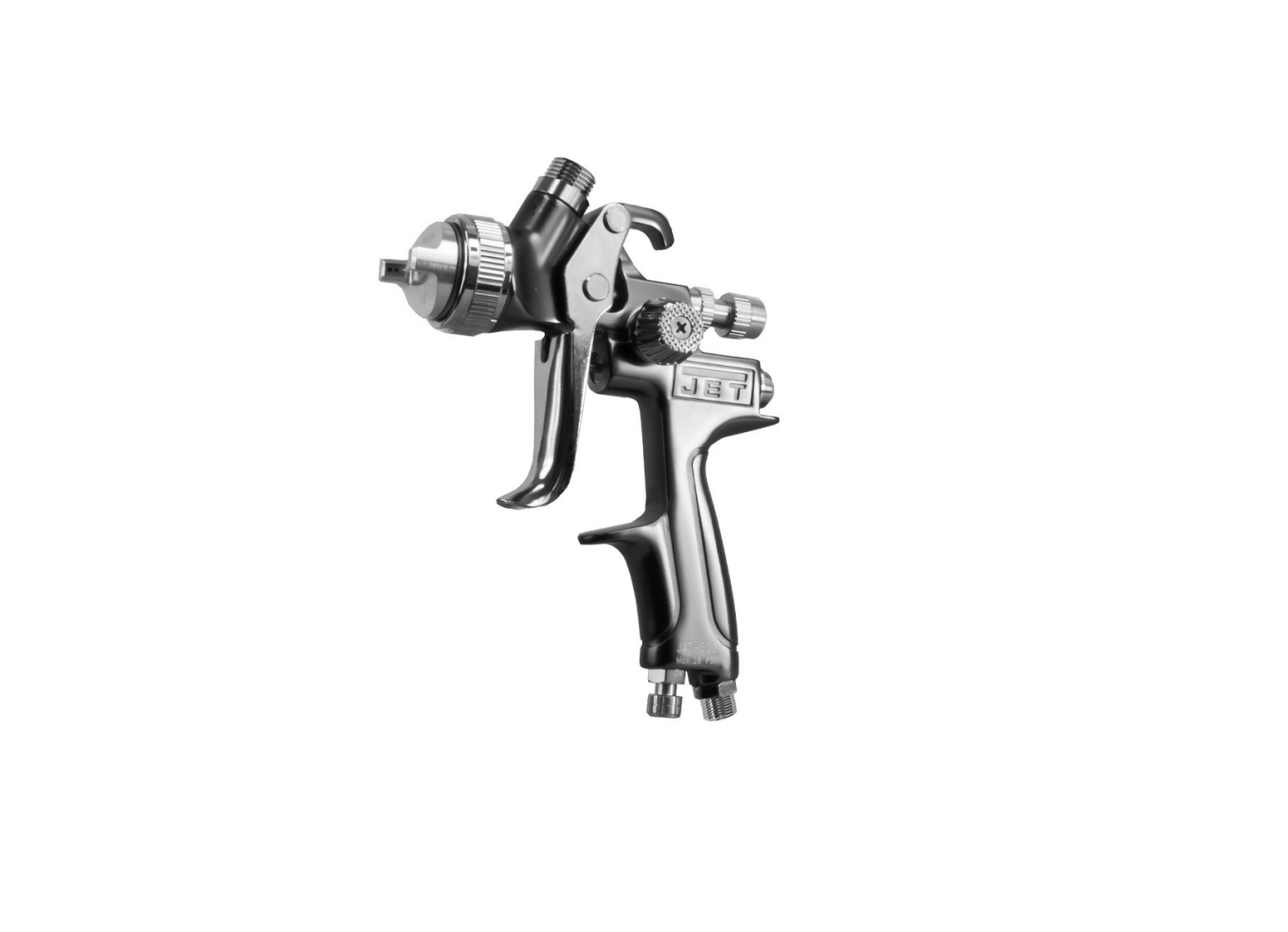
This manual is provided by JET, covering the safe operation and maintenance procedures for a JET Model JAT-500 Pneumatic Spray Gun. This manual contains instructions on safety precautions, general operating procedures, maintenance procedures and parts breakdown. Your tool has been designed and constructed to provide consistent, long-term operation if used in accordance with the instructions set forth in this document.
The instructions and warnings in this manual may not encompass all possible workplace environments. The operator is expected to take appropriate precautions and exercise common sense. As with any tool operation, safety of operator and bystanders should be first priority.
If there are questions or comments, please contact your local supplier or JET. JET can also be reached at our web site: www.jettools.com.
Record the serial number and purchase information of your tool on the cover of this manual for quick access. Retain this manual for future reference. If the tool transfers ownership, the manual should accompany it.
Tool specifications
| Model number | JAT-500 |
| Stock number | 505500 |
| Gun type | HVLP (High Volume Low Pressure) |
| Feed type | Gravity |
| Cup capacity | 600cc |
| Fluid nozzle provided | 1.3 mm |
| Fluid output | 170 cc/min |
| Maximum fan pattern size | 280 mm |
| Air consumption | 10 CFM at 28 PSI (2 bar) |
| Working pressure | 15-28 PSI (1.05-2 bar) |
| Air Inlet | 1/4 in. PS |
| Fluid inlet | M16 x 1.5P |
| Overall length | 13.1 in. (332.74 mm) with cap; 7.87 in. (200 mm) without cap |
| Body material | Die casting |
| Fluid tip and needle material | Stainless steel |
| Net weight, gun body | 1.01 lb. (0.46 kg) |
| Net weight, accessories | 0.59 lb. (0.27 kg) |
| Shipping weight | 2.05 lb. (0.93 kg) |
1 The specified values are emission levels and are not necessarily to be seen as safe operating levels. As workplace conditions vary, this information is intended to allow the user to make a better estimation of the hazards and risks involved only.
Specifications were current at time of publication, but because of our policy of continuous improvement, JET reserves the right to change specifications at any time and without prior notice, without incurring obligations.
Setup and Assembly
Any missing parts or damage should be reported immediately to your JET® distributor. Do not use a damaged tool. Read this instruction manual thoroughly for operation, maintenance and safety instructions.
Box contents:
1 Spray gun1 Gravity feed cup, 600cc1 Nylon strainer1 Spanner1 Bristle brush1 Operation and parts manual1 Warranty card
Operation
- Blow out air line to remove any dirt or moisture, then connect air supply hose to tool’s air inlet.IMPORTANT: Connecting a quick-change coupling directly to the tool is not recommended, as vibration may cause the connection to fail. Instead, add a leader hose and install any quick-change couplings farther down the line.
- Unscrew cup lid and add fluid to be sprayed. (Follow paint manufacturer’s instructions for proper mixing.)
- Set regulator to desired air pressure. (Refer to gun’s rated maximum pressure).
- Loosen air cap knurled ring and rotate air cap horns to effect horizontal or vertical spray. Retighten air cap. Horizontal horns (as shown in Figure 1) will produce vertical pattern for side-to-side motion. Vertical horns produce horizontal pattern used for top-to-bottom motion.
- Squeezing trigger part way opens air valve. Squeezing further retracts fluid needle, thus releasing fluid where it is atomized by the air flowing through air cap.
- Rotate fluid control knob clockwise to decrease flow of material, counterclockwise to increase
- Rotate fan control knob counterclockwise for full, flat spray pattern; clockwise for narrower pattern.
NOTE: To reduce overspray and obtain maximum efficiency, always spray with the lowest possible air pressure/fluid flow combination.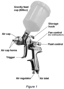 Spray gun movementThe gun should be held perpendicular to surface being covered, and moved parallel with it at a consistent pace. See Figure 2. The stroke should be started before the trigger is pulled, and the trigger released before the stroke is ended. Distance between gun and surface should be 6 to 12 inches depending upon material and atomizing pressure. Deposited material should be even and wet. Lap each stroke over the preceding stroke from 1/3 to 1/2, to obtain a uniform finish.
 Maintenance
Note: All parts on a spray gun should be screwed in hand tight at first; this will avoid the possibility of cross threading the parts. If parts cannot be turned by hand easily, make sure you have the correct parts, unscrew, realign and try again. Never use undue force in mating parts.All nozzles and needles are precision made they should be handled carefully. When changing to a different nozzle size, make sure that complete nozzle set is exchanged (air cap/nozzle/needle).Adjust fluid control knob so that when gun is triggered, air-flow occurs before fluid-flow.
CAUTION Do not probe any holes in nozzle with metal instruments, as damage to spray gun can affect proper operation.
Cleaning
- After use, remove cup and drain residual material. Rinse cup with a cleaning solution or water, depending upon material used. Place cleaning solution into cup and install on gun. Spray solution through the gun unit it sprays clear. Do NOT immerse the entire gun in solvent.
- Disconnect air hose from tool.
- Remove air cap and clean. Make sure holes in horns are clean.
- Use solvent and the provided brush to remove any deposits around fluid nozzle.
- For more detailed cleaning, use provided spanner to remove fluid control knob, fluid nozzle, and needle (in that order). Clean nozzle and needle with brush and solution. Reassemble parts by reversing above order.
- Periodically lubricate the gun. Use a light machine oil (Air Tool Oil or SAE #10) on the following areas. Do not use lubricants containing silicone.
- Fluid needle packing (to prevent needle from sticking)
- Air valve packing
- Trigger pivot point
- Threaded parts
Storage
Hang the spray gun by its hook when not in use, to prevent leaks or blockages. Disconnect air hose before storage.
Air system requirements
- Use proper air hose size (refer to tool specifications). The hose should be just long enough to serve the working area. Excessive hose length will cause pressure drop.
- Make sure air compressor supplies clean, dry air at correct CFM for tool.
- Set air pressure according to tool specifications.
CAUTION Excess air pressure and/or unclean air will shorten the tool’s life and may create a hazardous situation.
- Drain water from air compressor tank daily, as well as any condensation from air lines. Water in the air line may enter the tool and cause damage.
- Change filters on the air system on a regular basis.
- Air-line pressure may be increased accordingly to compensate for extra-long air hoses (usually over 25 feet). Inside diameter of hose should be minimum 3/8-inch.
General Air Tool Information
If the air tool is not performing according to specifications, the following are among the most common causes. (See also “Troubleshooting” section.)
- Contaminated air such as a dirty air system or water in the system.
- Using wrong size tool for the job.
- Poor maintenance practices, such as using excessive air pressure or air volume.
- Improper or no lubrication.
Air System Recommendations
Equip the air compressor intake with a replaceable air filter that can be easily cleaned.
Use safety shut-off valves so air flow can be stopped quickly in case of a line break.When using multiple hoses, air hoses should be larger than leader hose. Join multiple hoses directly, rather than with quick connect fittings which may cause pressure drops and tool power reduction.
Use anti-whip devices across hose couplings to prevent hose from whipping in the event of a hose failure or coupling disconnect.Always use moisture traps at the compressor for the main distribution line. Use moisture traps on each downline that is to be used for air tools.
RecyclingProtect the environment. Your tool contains materials which can be recovered or recycled. When its useful life has expired, please leave tool at a specialized facility.
Troubleshooting JAT-500 Spray Gun
| Problem | Possible cause | Remedy |
 RIGHT RIGHT |
Correct normal pattern | No correction necessary. |
| WRONGHeavy top orbottom pattern |
Dirty or damaged air cap. Dirty or damaged fluid tip. | Rotate air cap 180-degrees: If pattern is following air cap, problem is in air cap. Clean and inspect. If pattern does not correct, replacement is necessary. If pattern is NOT following air cap, problem is with fluid tip. Clean and inspect tip for dried paint, dirt or damage. If pattern does not correct, replacement is necessary. |
| Pressure too high for material viscosity being sprayed. | Reduce air pressure. | |
| Increase material viscosity. | ||
| Pattern may also be corrected by narrowing fan size with spray width adjuster control knob. | ||
| WRONG |
Dirty or distorted air horn holes | Rotate air cap 180-degrees: If pattern is following air cap, problem is in air cap. Clean and inspect the horn holes. If horn holes are distorted, replacement is necessary. |
| One of the air horn holes completely obstructed. | ||
| WRONGGun spiking |
Air getting into paint stream. | Check and tighten fluid needle packing nut. |
| Tighten fluid nozzle. | ||
| Check fluid nozzle seat for damage | ||
| Check for poor gun-to-cup seating. | ||
| Check that cup is correctly fastened on gun. | ||
| Material bubbles or “boils” in cup. | Excess air blowing back into cup | Tighten fluid nozzle. |
| Check fluid nozzle seat. | ||
| Check for damaged fluid seat on nozzle or seat on gun head. | ||
| Gun leaks from fluid nozzle. | Foreign substances between fluid nozzle and needle. | Disassemble and clean nozzle and needle. |
| Paint emerges from needle packing. | Needle packing is damaged or missing. | Replace packing. |
| Too much overspray | Gun too far away. | Move gun closer to work surface. |
| Excessive fluid | Reduce fluid flow. | |
| Excessive air pressure. | Reduce air flow | |
| Nozzle too large for project. | Try smaller nozzle kit. | |
| “Orange peel” finish (textured instead of smooth). | Insufficient air pressure for proper atomization. | Increase air flow. |
| Fluid too thick. | Thin the fluid and retry. | |
| Applying fluid at an angle | Apply perpendicular to work surface. |
Spray nozzle applications
Below are general applications for accessory nozzles available for this spray gun. This is only a general guide; consult the fluid material manufacturer for more information on efficient use of their product
| Nozzle size | General application | |
| mm | inch | |
| 1.3 | 0.05 | clearcoats, water-based and single stage paints |
| 1.4 | 0.055 | basecoats, thicker clearcoats, single stage urethanes |
| 1.7 | 0.066 | primers; upper level for urethanes, lower level for polyurethanes |
| 2.1 | 0.083 | heavy-bodied primers |
Replacement parts
Service parts are listed on the following pages. To order parts or reach our service department, call 1-800274-6848 Monday through Friday, 8:00 a.m. to 5:00 p.m. CST. Please have the stock number and serial number of your tool available when you call, so that we may serve you quickly and accurately.
#505500, JAT-500, HVLP Spray Gun exploded view T500-15
#505500, JAT-500, HVLP Spray Gun – parts list
| Index | Part No. | Description | Qty |
| 1 | JAT500-01 | Air cap assembly 1.3mm | 1 |
| 2 | JAT500-02 | Fluid nozzle 1.3mm | 1 |
| 3 | JAT500-03 | Distributor | 1 |
| 4 | JAT500-04 | Gun body | 1 |
| 5 | JAT500-05 | Fluid inlet for 600cc | 1 |
| 6 | JAT500-06 | Needle packing | 1 |
| 7 | JAT500-07 | Spring | 1 |
| 8 | JAT500-08 | Needle packing seat | 1 |
| 9 | JAT500-09 | Fluid needle assembly 1.3mm | 1 |
| 10 | JAT500-10 | Fluid needle spring | 1 |
| 11 | JAT500-11 | Fluid control knob | 1 |
| 12 | JAT500-12 | Air valve | 1 |
| 13 | JAT500-13 | Air valve shaft | 1 |
| 14 | JAT500-14 | Air valve gasket | 1 |
| 15 | JAT500-15 | Spring | 1 |
| 16 | JAT500-16 | Screw | 1 |
| 17 | JAT500-17 | Fan control assembly | 1 |
| 18 | JAT500-18 | Fan control knob | 1 |
| 19 | JAT500-19 | Screw M4x8 | 1 |
| 20 | JAT500-20 | Air inlet 1/4in. PS | 1 |
| 21 | JAT500-21 | Air regulator assembly | 1 |
| 22 | JAT500-22 | Pivot pin | 1 |
| 23 | JAT500-23 | Pin with hole | 1 |
| 24 | JAT500-24 | E-ring | 2 |
| 25 | JAT500-25 | Trigger | 1 |
| 26 | JAT500-26 | Nylon cup 600cc (not shown) | 1 |
| 27 | JAT501-26 | Wrench (not shown) | 1 |
| 28 | JAT501-27 | Bristle brush (not shown) | 1 |
| 29 | JAT500-29 | Nylon strainer (not shown) | 1 |
JAT500-RPK, Repair Kit, contains 6,7,10,14,15,24(2)JAT500-NK, Replacement Nozzle Kit 1.3mm, contains #1,2,9
Accessories for JAT-500:505590, 600cc Aluminum cup with plastic lid505591, Nozzle kit 1.4mm (includes air cap, fluid nozzle and fluid needle)505592, Nozzle kit 1.7mm (includes air cap, fluid nozzle and fluid needle)505593, Nozzle kit 2.1mm (includes air cap, fluid nozzle and fluid needle)505596, Spray Gun Cleaning Kit, 17pc.
505596
427 New Sanford Road Lavergne, Tennessee 37086Phone: 800-274-6848www.jettools.com16 JAT-500 HVLP Spray Gun
report this ad
References
[xyz-ips snippet=”download-snippet”]