
110*80mm,105
JC500
LTE Android BoxUser ManualV1.0
![]()
1. Introduction
1 .1 Overview
JC500 uses a high-performance quad-core ARM CPU, integrates a high-performance GNSS module, a 4G communication module, a WiFi module, and a BT module, and features 1080P HD cameras (optional), a 6-axis gravity sensor, RS232 ports, and extended I/O ports. The input supply is 9–36V. These features enable JC500 to: upload data; pinpoint, track, and monitor vehicles; and collect video data, mileage, fuel consumption, and Boolean values. Besides, driving behavior analysis and the driver monitoring system (DMS) underpinned by advanced software technologies make JC500 suitable for the rental, logistics, public transport, engineering, and many more industries.
1.2 Packing List
| Item | Quantity |
| Main unit | 1 |
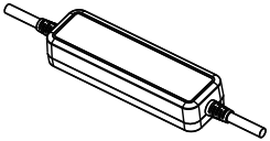
| 3-in-1 antenna (WIFI+4G+GPS) | 1 |
| Power cable | 1 |
| SOS key cable (speaker and MIC integrated) | 1 |
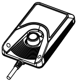
| Front-view camera (optional) | 1 |
| Rear-view camera (optional) | 1 |
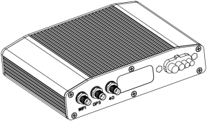
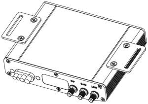
1.3 Appearance

1.4 Interfaces and Accessories
1.4.1 Interfaces
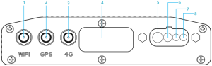
- WiFi ANT interface
- GPS ANT interface
- 4G ANT interface
- Extended ports (RS232/I/O)
- PWR cable connector
- SOS cable connector
- Front-view camera interface
- Rear-view camera interface
- USB port
- SIM card tray
- TF card slot
- Reset hole
- Red
- Green
- Blue
1.4.2 Accessories


Power cable *1 Antenna *1 SOS key cable *1 3M adhesive pad *4

![]()
AHD camera (optional) Main unit support plate *2 Screw *4
1.5 Operations
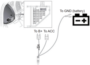
1.5.1 Power-On
- Power off the device and insert a TF card (Class 10 or above; max. 128GB) and a SIM card;
- Connect B+ and GND of the power cable to the positive and negative of the vehicle battery;
- Connect ACC with the vehicle ignition signal cable. In this case, when the vehicle starts, the device will automatically switch its power on.
- When the vehicle is ACC OFF, the device stays in sleep mode.
1.5.2 DVR
- ACC ON: The device operates and records.
- ACC OFF: The device sleeps and doesn’t capture videos.
- Storage: The video segments are saved every 3mins.They are normally saved in:Videos captured by the front-view camera:DVRMEDIA/CarRecorder/GENERAL/ForwardCam/Videos captured by the rear-view camera:DVRMEDIA/CarRecorder/general/InwardCam/
- Videos are recorded cyclically, that is, when the TF card reaches the full capacity, old videos will be overwritten by new ones.
- The device will sound an alert every 5mins when the free space of the TF card is less than 800MB or no TF card is identified.
- Upon the detection of a collision, the device will capture a 15s video (7s before and 8s after the time to trigger) and save the video to “DVRMEDIA/CardRecroder/EVENT”. The event videos can be uploaded to a file server designated by you.
1.5.3 Remote Real-time MonitoringYou can watch real-time videos via the mobile app or web client.
1.5.4 WiFi
| ACC ON | You can configure whether to enable the WiFi hotspot of your device upon ACC ON.The name of the hotspot is the device IMEI and the password is the last 8 digits of the IMEI. |
| ACC OFF | The hotspot is disabled. |
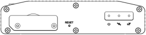
1.5.5 LED Indicators
| Red | Solid on | The device operates normally. |
| Slow blink (on every 10s) | The device is in sleep mode. | |
| Fast blink (on every 1s) | Storage error | |
| Off | The device is powered off. | |
| Green | Solid on | The GPS module operates normally after satellite search is complete. |
| Slow blink | The GPS module is in search of satellites or encounters an exception. | |
| Off | The device is powered off or in sleep mode. | |
| Blue | Solid on | The 4G module operates normally. |
| Slow blink | The 4G module encounters an exception or is in search of signals. | |
| Fast blink (on every 1s) | SIM card error | |
| Off | The device is powered off or in sleep mode. |
1.5.6 SOS KeyPress the SOS key for 3s, the device will send out an SOS alert.
1.5.7 SpeakerJC500 integrates DMS-based pre-warning feature (sold separately), which means when the visual AI detects driver fatigue, it will voice up to remind the driver.
2. Specifications and Features
2.1 Specifications
| Hardware Parameters | • Android 8.1 Go, ARM Cortex A53 1.4GHz, 2G+16GB• All bands (4G/WCDMA/GSM) and WiFi hotspot• 2.4G WiFi 802.11 b/g/n• GPS+BDS• Dual channel AHD remote camera• Microphone• Speaker• 6-axis G-Sensor• BT (data transfer supported)• TF card (max. 128GB) supported• USB data port• Extended ports: RS232 (*2), Input (*2), Output (*2), and ADC (*1) |
| Applicable Environment | • Operating temperature: –20°C to 70°C• Storage temperature: –30°C to 85°C• IP rating: IP53• Vibration standard: ISO 16750 |
| Electrical Performance | • Input voltage: 9–36V |
2.2 Features
- Remote surveillance and GPS-based positioning and tracking
- SOS alert
- Bad driving behavior analysis (optional)
- DMS-based driver fatigue pre-warning (optional)
- Dual-channel video cyclic recording
- Remote images and videos obtainment
- Auto upload of event videos
- Real-time remote monitoring
- Viewing and playback of recorded videos
- Remote power/fuel cutoff
- Extended ports (RS232, ADC, and I/O)
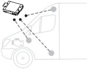
3. Installation
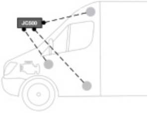
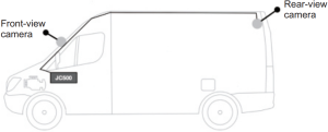 Figure 3-1 Installation Diagram of Front-view camera and rear-view camera
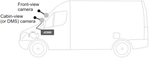
Figure 3-2 Installation Diagram of Front-view camera and cabin-view (or DMS) camera
3.1 Installing the Main Unit
Check and ensure the vehicle is in good condition and then select an installation position that is in good ventilation, dustproof, damp-proof, and easy for cabling and future maintenance.
3.1.1 Attach the 3M adhesive pad
Preparation:

JC500 main unit *1 3M adhesive pad *1
1. Select a proper installation position inside the cabin and clean it.
2. Remove the protective film from the 3M adhesive pad and attach it to the base of the main unit.
3. Remove the protective film from the other side of 3M adhesive pad and attach the main unit to the installation position.
4. Wait for 2 hours until the 3M adhesive pad attaches firmly.
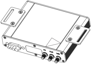
3.1.2 Install the support plate
Preparation:
![]()
![]()
JC500 main unit *1 Support plate *2 Screw *4 Screwdriver *1
1. Select a proper installation position and wipe it clean.

2. Fixate the two support plates to the bottom of the main unit with screws.
3.Drill holes into the installation position and fixate the main unit with screws. Or you can fixate the main unit with cable ties.
3.2 Installing Key Parts
3.2.1 Attach SIM and TF cardsTo attach the SIM and TF cards, do as follows:
1. Loosen the 2 screws from the SIM/TF protective plate at the back of JC500.
2. Remove the plate.
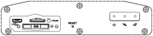
3. Use a SIM ejector tool (or paperclip) to unlock the SIM card tray. If a TF card is already in the TF card slot, you can push and then pull the card out.

Press here to unlock the SIM card tray
4. Fit both cards in and then fixate the protective plate with screws.
Note: To remove both cards, repeat the above procedure.
3.2.2 Install the antenna
Take the 3-in-1 antenna out and attach them to the corresponding interfaces by the labeled and silk-printed characters.
3.2.3 Install the front-view camera
- Take the front-view camera out and connect it to the corresponding interface on the device securely.
- Select a proper position. If the device is online, you can check via TrackSolid App whether the videos meet your requirements.
- Wipe the position clean, remove the protective film off the 3M adhesive pad, and attach the camera to position.
- Use the screwdriver to tighten the screw of the camera, so it keeps at a fixed angle.
3.2.4 Install the rear-view camera
- Take the rear-view camera out and connect it to the corresponding interface on the device securely.
- Select a proper position. If the device is online, you can check via TrackSolid App whether the videos meet your requirements.
- Wipe the position clean, remove the protective film off the 3M adhesive pad, and attach the camera to position.
- Use the screwdriver to tighten the screw of the camera, so it keeps at a fixed angle.
3.3 Wiring
3.3.1 Power cable wiring
3.3.2 Wiring for remote power/fuel cutoff
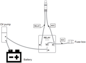
- By sending commands via the Web client or mobile app to the relay, you can cut off the power or fuel supply of the vehicle.
- This feature only works when the GPS module has successfully fixed and the vehicle speed is under 20km/h; otherwise, the execution of the cutoff command delays.
4. TrackSolid
4.1 Installation
By integrating features such as real-time tracking, playback, remote image and video capture, monitoring, geo-fence, and alert options, TrackSolid enables you to monitor your vehicle anywhere, anytime. To get the latest TrackSolid operation guide, please scan the following QR code.

5. Others
5.1 Safety Warnings and Instructions
1. Toxic and Hazardous Substances Checklist
| Statement on Toxic and Hazardous Substances in Electronic Information Products | ||||||
| Item | Toxic and Hazardous Substances or Elements | |||||
| Lead(Pb) | Mercury(Hg) | Cadmium(Cd) | Hexavalent chromium(Cr6+) | Polybromi nated Biphenyls(PBB) | Polybromi nated diphenyl ether(PBDE) | |
| Main unit | X | O | O | O | O | O |
| Accessories | X | O | O | O | O | O |
| O: This indicates the content of hazardous substances in all homogenous material of the part conforms to GB/T 26572 standards.X: This indicates the content of hazardous substances in at least one homogeneous material of the part exceeds the limit specified in GB/T 26572. |
2. Limitation on built-in battery
| Operating temperature | Charging temperature: 0℃ to 45℃ |
| Discharging temperature: –20℃ to 60℃ |
 report this ad
3. Precautions on Usage
- Ensure that the power cable is installed securely; Otherwise, it may fail to supply power for the device due to loose contact resulted from violent collision.
5.2 Troubleshooting
- The device fails to go online.a. Check whether the SIM card is active and valid, inversely inserted, or loose.b. Check if the device can power on normally by observing the LED indicator.c. Check if the login IMEI is consistent with that on the device.d. Check if the SIM card needs recharge.
- The device is slow in positioning.a. Check if the 3-in-1 antenna is correctly attached. The antenna should be placed horizontally with the BDS/GPS side facing upward.b. Ensure that you have parked your vehicle in an open area, where no high-voltage cables, large-area glass walls, or other signal-interfering objects exist.
- The camera fails to capture videos.a. Check if the red LED is solid on after the device is powered on.b. Check if the camera and the main power bundle are securely connected.c. Replace with a new camera to see if the new one captures normally.
[xyz-ips snippet=”download-snippet”]