![]()
GNSS VEHICLE TERMINALUSER MANUAL V2.0
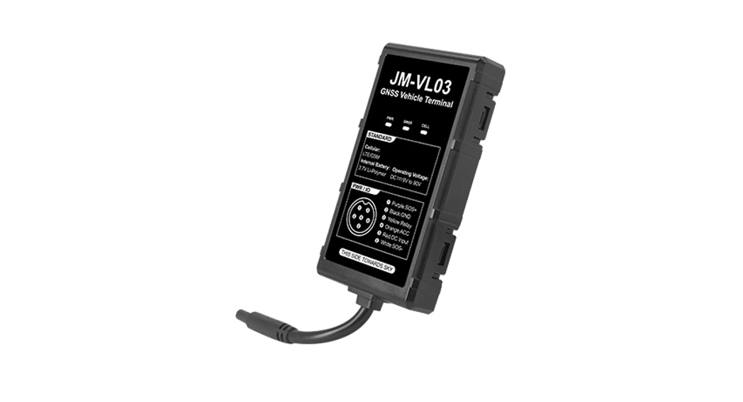
Product overview
Real-time trackingDriving behavior analysis (4 types)Serial port (optional)Over-speed alert SOS alertTamper alert Removal alertPower-supply-cut alertLow power alert Vibration alert Geo-fence
Standard Parts List
| Item | Quantity |
| JM-VLO3 | 1 |
| Power cable (Length:1m) | 1 |
| Relay | Optional |
| Panic button | Optional |
Specification
| Network | 4G & 2G |
| Frequency | JM-VLO3E:FDD: B1/B3/B5/B7/B8/B20TDD: B34/638/B39/B40/B41GSM: 900/1800 MHz |
| JM-VLO3A:LTE: B1/133/137/138/B28 GSM: 850/900/1800/1900 MHz | |
| JM-VLO3M:LTE: B2/B4/B5/B7/B12/1313 GSM: 850/900/1800/1900 MHz | |
| Location accuracy | <10 meters CEP |
| Relay | Optional |
| TIFF (open sky) | Avg. hot start51 sec Avg. cold start532sec |
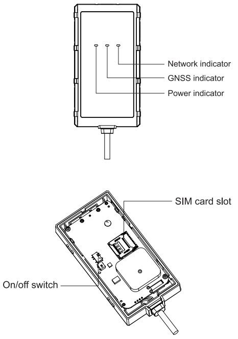
| Indication | GPS (Blue), Cellular (Green), Power (Red) |
| Battery | 60mAh, 3.7V Li-Polymer battery (270mAh/3.7V optional) |
| Operating voltage | 9-90VDC |
| Operating temperature | —20–C to +70″C |
| Device weight | 69g |
| Device dimension | 94.3mm*50.4mm*15.0mm |
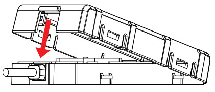
Product Setup
- Prepare a micro SIM card that supports the same network as this device.

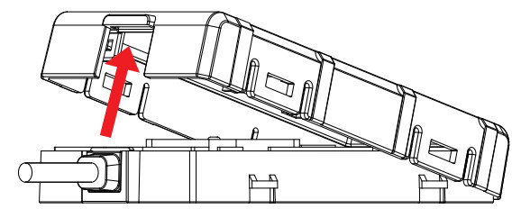
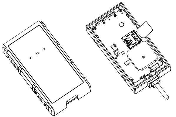
- Remove the upper cover of the device.
- Insert SIM card into the slot and toggle the switch to ON.
- Press the upper case down and make sure all 5 clips are completely in place.

LED Indication
Power Status (Red)
| On for 0.3s and off for 0.3s | Low power |
| On for 1s and off for 3s | Fully charged |
| On for 0.1s and off for 3s | Working normally |
| Solid on | Charging (Higher priority than the status of low power) |
| Off 1 | The battery is exhausted/Internal failure |
| GNSS Status (Blue) | |
| On for 0.3s and off for 0.3s | Searching GNSS signal |
| Solid on | Positioned |
| Off | GNSS module is in sleep mode or not working |
| Cellular Status (Green) | |
| On for 0.3s and off for 0.3s | Network initializing |
| On for 1s and off for 3s | Receiving signal normally |
| On for 0.1s and off for 3s | Network connected |
| Solid on | Calling |
| off | No signal received/No SIM card detected |
Power supply Status (Red, Blue, Green)
| Red, Blue and Green on for 3s | Connected/disconnected power supply |
Interfaces
6 Pin Standard Version
| Interface | Color | Description |
| V+ | Red | Power + (9-90V) |
| V- | Black | Power – Ground pin |
| ACCESS | Orange | Vehicle ignition detection |
| Relay | Yellow | Cut-off vehicle fuel supply |
| SOS+ | Purple | SOS trigger Pin |
| SOS- | White | SOS Ground Pin |
6 Pin RS485/TTL Version (Optional)
| Interface | Color | Description |
| V+ | Red | Power + (9-90V) |
| V- | Black | Power- Ground Pin |
| Tx/RS485 A | Blue | TTL Tx or RS485 A |
| Rx/RS485 B | Green | TTL Rx or RS485 B |
| SOS+ | Purple | SOS Trigger Pin |
| SOS- | White | SOS Ground Pin |
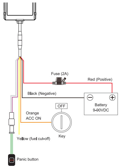
Wiring of Standard Version
Tips for finding the right wires:
- Use a multimeter to find out the positive and negative sides of the vehicle battery.Note: No matter the ignition key is switched to ON or OFF, the current battery voltage can be shown in the multimeter.
- The way to find ACC wire: Connect multimeter’s black probe to the negative side, and connect the red probe to a random wire, at this moment, the voltage shown in the multimeter is OV; turn the key to ON, if the supply voltage is shown, that’s the correct ACC wire.
- Connect the two connectors together, if the vehicle has no connector, please connect the device’s wires to the corresponding vehicle wires.
Installation recommendation
Please install the device under the guidance of professional personnel.


Note:
- The device should face up to the sky.
- Metal thermal barrier or heating layer, which are always installed on the windshield, may affect the signal, please avoid installing the device under these objects.
Platform & APP
- Login service platform Please login to the designated service platform to set and operate the device.
- Download APP Please download and install the APP on the designated website, APP Store, or Google Play store.
SMS Commands
| VERSION# | Query the firmware version | |
| STATUS# | Query the status | |
| PARAM# | Query parameters (IMEI, SOS numbers, center number, and time zone) | |
| WHERE# | Query the current location | |
| URL# | Query the location link | URL#Network connected and position Ifixed: <05-22 10:53> http://maps.google.com/maps? q=N23.111712,E114.409264 Network not connected but position fixed: <05-2210:53> http://maps.google.com/maps? q=N23.111712,E114.409264 Network not connected and position not fixed: NO DATA! |
| PRSSET# | Query network parameters (GPRS status, APN, server address, URI_, etc.) | GPRSSET#GPRS,ON;Currently use APN:CMnet,,;APN Auto set:OFF; SERVER.1,test.topstargps.com, 11139;URL,http://maps.google.com/maps?g= |
| APN# | Set APN parameters | APN, apnname# OR APN, name,user,pwd#Close automatic APN and set by yourself. APN#Check the current APN parameters. |
| SERVE R# | Set the parameters of the server | SERVER.mode.domainName/IP, portprotocol#eg:SERVER.1.www.ydpal.com,8011.0#SERVER,0.211.154.135.113, 011.0#mode = 1 means set with domain namemode = 0 means set with IPaddressprotocol = 0 means connect server with TCP protocolprotocol = 1 means connect the server with UDP protocolSERVER#Check the current sever parameters |
| SOS# | Set SOS numbers | SOS,A,phone number 1,phone number 2,phone number 3# Add SOS phone number. SOS,D, sequence number 1, sequence number 2, sequence number 3# Delete the phone number according to the sequence number. SOS, D, phone number# Delete the matching SOS phone number. SOS# Check the SOS phone number. |
| TIMER# | Set the time interval for the GNSS module to send data | TIMER,T1,T2# T1=5-18000 or 0, upload interval when ACC ON, unit: seconds; 0 means no upload; default is 10; T2=5-18000 or 0, upload interval when ACC OFF,unit: seconds; 0 means no upload; default is 10. TIMER# Check the current parameters of T1 and T2. |
| RELAY# | Control the power and fuel | RELAY,A# A=0/1.0 means connection, 1 means cut off;default: 0. RELAY# Check the status of the control. |
| ADT# | Set parameters to upload voltage values of the external battery | ADT,A,T#A=ON/OFF, On/Off ADC data upload,default: OffB=5-3600, Default: 600s; Upload time interval,unit: seconds ADT,OFF#Turn off analog data upload ADT#Query the ADT port parameters |
| RESET# | The device restarts 20 seconds later after receiving the command. | RESET#The device would reboot in 20S after receiving the command. |
| SPEEDCHECK# | Set and query the sudden speed change alert | SPEEDCHECK,ON,M,T,A,D# M=0/1,alarm reporting method, 0: only GPRS,1: GPRS+SMS,default: 0 T=1-30, detection duration, unit: seconds, default: 4 A=10-300(km/h),threshold ofHarsh acceleration speed difference default 30D=10-300(km/h),difference threshold for sudden brake deceleration speed, default 50 SPEEDCHECK,OFF#Turn off the SPEEDCHECK alarm SPEEDCHECK#Query the SPEEDCHECK port ‘parameters |
| SWERVE# | Set and query the sharp cornering alert | SWERVE,ON,M,A,S,T#M=0/1/,alarm reporting method,0: only GPRS,1: GPRS+SMS, default: 0 A=10-180(degrees),trigger alarm Angle threshold, default 30 S=10-200(km/h),trigger alarm Speed threshold, default 60T=1-30 detection duration, unit: seconds, default 3 SWERVE,OFF#Turn off the SWERVE alarm SWERVE# Query the SWERVE port parameters |
| PULLALM# | Set tamper alert | PULLALM,ON, M, N,T#M=0/1/, alarm reporting method,0: only GPRS,1: GPRS+SMS, default:0 N=1-40, Threshold of mean change, unit:0.1g g: acceleration of gravity, default 30T=2-10 The time interval between power cut-off event (triggered before rollover) and rollover event, unit: seconds, default 5 PULLALM, OFF# Turn off the PULLALM alarm PULLALM# Query the PULLALM port parameters |
Troubleshooting
| Type | Use |
| Unable to connectto tracking platform | Check the APN and IP settings.Check whether the data service of the SIM card is enabled.Check the balance of the SIM card. |
| Tracker shows offline | Check whether external power is still connected. Check if the vehicle entered the network blind area. Check the balance of the SIM card. |
| Unable to locate | Make sure the top side facing upward without metallic things shielded.Make sure it’s not in an area with no satellite coverage. |
| Location drift | In areas with poor GNSS signal all building around or basement), drifting may happen. Check whether vibration happens around to trigger the accelerator. |
| No command reply | Make sure the command format is correct. The vehicle may be in-network blind area.Make sure SIM card is well inserted and has * SMS service. |
Warranty instructions
- The warranty is valid only when the warranty card is properly completed and upon presentation of the proof of purchase consisting of the original invoice indicating the date of purchase, model, and serial No.of the product. We reserve the right to refuse a warranty if this information has been removed or changed after the original purchase of the product from the dealer.
- Our obligations are limited to repair of the defect or replacement of the defective part or at its discretion replacement of the product itself.
- Warranty repairs must be carried out by our Authorized Service Warranty cover will be void, even if a repair has been attempted by any unauthorized service center.
- Repair or replacement under the terms of this warranty does not provide the right to extension or renewal of the warranty period.
- The warranty is not applicable to cases other than defects in material, design, and workmanship.
Maintenance Record
| Date | Service by |
| Product Model | |
| IMEI Number | |
| FailureDescription | |
| Comments |
Output power:GSM 900MHz: 29dBm(MAX) , GSM 1800MHz: 26 dBm(MAX)Declaration of Conformity Hereby, Shenzhen Jimi loT Co., Ltd declares that the radio equipment type JM-VLO3 of is in compliance with Directive 2014/53/EU. and this product is allowed to be used in all EU member states.
[xyz-ips snippet=”download-snippet”]