JC400 SeriesEdgeCam2 User Manual Version:v3.0
Please read this manual carefully prior to use. The content of this manual may change due to improvement in performance without prior notice.
Introduction
1.1 Packing List
| Standard |
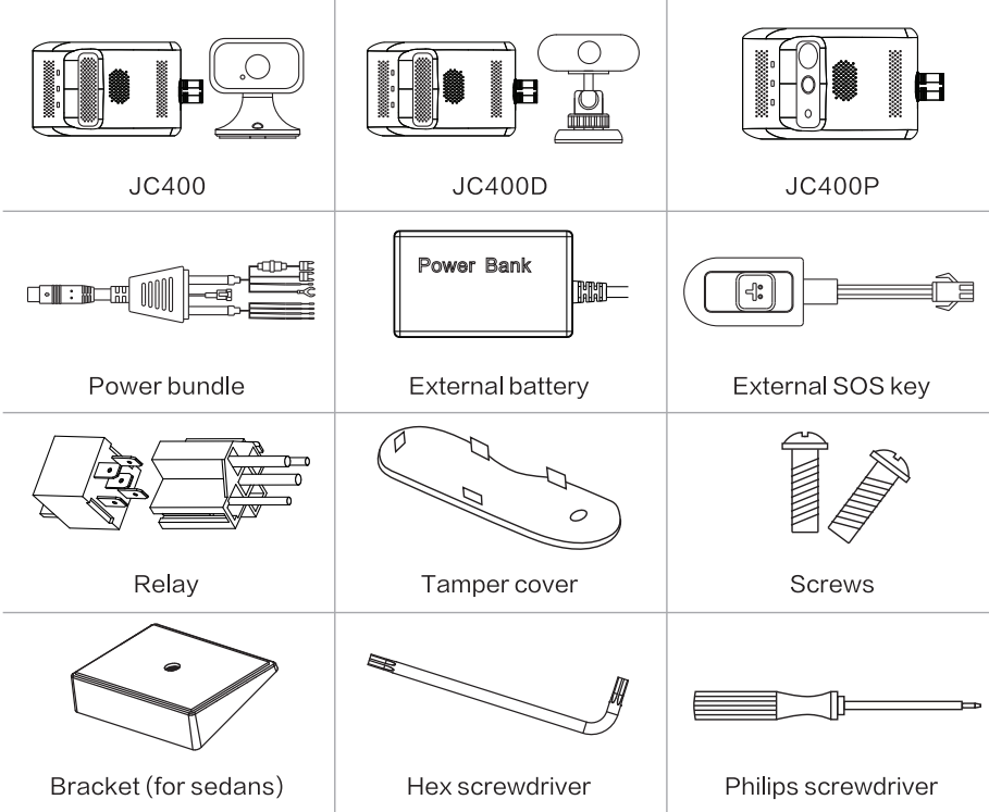 |
| Optional |
 |
Please check the product model you purchased carefully as the packing list varies with the model.
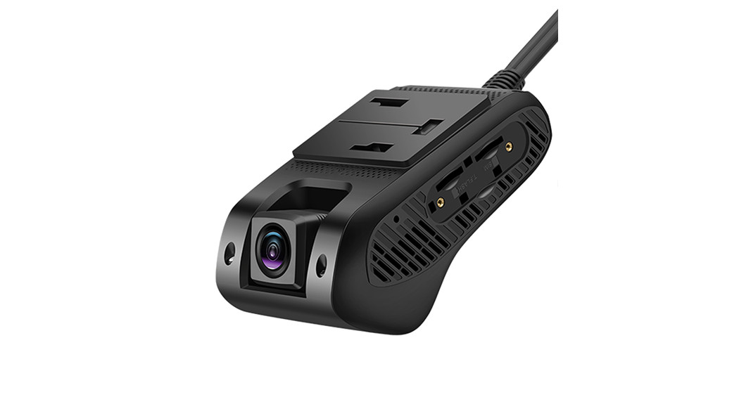
1.2 OverviewJC400 series uses 4G network for communication. For these dual-channel digital video recorders (DVRs), except to be able to record simultaneously, the two cameras can also record locally and live stream remotely at the same time. The front-facing HD camera is used for real-time recording; while the cabin-view camera with IR LED for monitoring at night time. Combined with DM S, driving behavior analysis, multiple alert options, and much more, they can assist the management in monitoring the vehicle condition and the driver’s behavior at any time. This is very useful to coach driver’s behavior, improve management efficiency, and lower operation costs, making the JC400 series an ideal option for remotely managing ridesharing, rental, public, government, and enterprise fleets.1.3 Appearance and LEDs1.3.1 Main Unit
| product Model | JC400/JC400D main unit |
| Camera | 1920×1080/25FPS/F 2.0/Full color |
1.3.2 Sub camera Options
| Product Model | JC400P | Integrated Version |
| Build-in Camera | 1280×720/15FPS/F2.0/ Full color in daytime and monochrome in dim light/No remote camera | 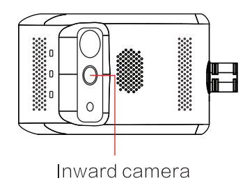 |
| Usage | Monitor the cabin | |
| Product Model | JC400 | Remote Cabin-view Version |
| Remote AHD camera | 1280×720/15FPS/F2.0/Full color in daytime and Camera monochrome in dim light |  |
| Product Model | JC400D | DMS Version |
| DMS camera | 1280×720/15FPS/F2.0/ DMS Camera Monochrome all-day |  |
| Usage | Monitor the driver’s head | |
Refer to the specifications and features of the product model you purchased. If you have any questions, please contact your supplier.
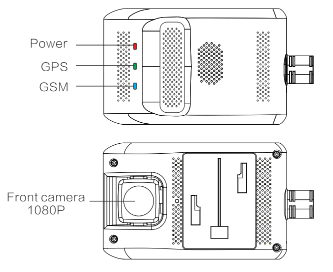
1.3.3 LEDs
|
LED |
Color | Connotation |
Status |
| Power LED
|
Red | Solid on | Device powered on (ACC ON) |
| Blink every lOs | Device in sleep (ACC OFF) | ||
| GPS LED | Off | No power connected | |
| GPRS LED | Green | Solid on | GPS signal normal |
| Blink every Is | Searching for GPS satellites | ||
| Off | Device in sleep (ACC OFF) | ||
| Defense LED | Blue | Solid on | Network healthy |
| Blink every is | Network error | ||
| No SIM | |||
| Off | Device in sleep (ACC OFF) | ||
| Defense LED | Blue | Fast blink for the 30s | Vibrating alert triggered |
| Blink every lOs | Defense on | ||
| Off | Defense off |
1.4 Wirings

| Cable | Definition | Color | Usage |
| Power | B+ | Red | To battery positive (9-30V), power input |
| GND | Black | To battery negative, power input | |
| ACC | Yellow | To ACC ON/Positive (9-30V), power input | |
| Relay | Green | To relay for remote power and fuel cutoff | |
| RS232 (optional) | I/O | / | To peripherals, such as oil sensors, card readers, etc. |
| SOS | SOS | / | To the external SOS key |
| Camera (optional) | Remote camera | / | |
| Battery | External battery | / | To provide a 45OrnAh backup battery for the device to protect it against power outages resulted from sudden power disconnection |
- Specifications and Features
2.1 Specifications
| Category Item | Parameter |
Remarks |
|
| Hardware | Memory | 1GB+16GB | |
| Standard version | 4G | FDD: B1/133/B5/137/138/89/1320 TDD: B38/639/1340/1341 (100M) | |
| 3G | WCDMA: B1/B2JB5/B8 | ||
| 2G | GSM: 850/900/1800/1900 | ||
| American version | 4G | FDD: B2/B3/134/135/B7/1312/B17 TDD: B38/B41 (100M) | |
| 3G | WCDMA: B2/134/B5 | ||
| 2G | GSM: 850/1800/1900 | ||
| WiFi | 2.4GHz | 802.11/b/g/n | |
| GNSS | Support | GPS/BDS | |
| Microphone | Support | For remote voice communication | |
| Speaker | Support | To notify drivers of status or events | |
| Interface/ Key | Reset key | Support | On the main unit |
| Interface | Micro USB | For commissioning and upgrade | |
| Others | Power supply | Fuse box | B+/ACC/GND |
| Supply voltage | DC 9-30V |
/ |
|
| Battery | External | 450mAh | |
| Operating temperature | _20°C-+70°C |
/ |
2.2 Features
|
No. |
Feature |
Description |
| 1 | Video recording | This enables the device to record in a loop when the vehicle is moving. |
| 2 | Live video | This enables the device to live stream images captured by cameras via the LTE network to the platform (web or app). |
| 3 | Tracking | This enables the device to upload location data and motion information via the mobile network to the platform for analysis. |
| 4 | Event alert | This enables the device to upload alert messages and video files to the platform when an event is triggered by a collision, vibration, dangerous driving behavior, emergency, DMS reminder, speeding, etc. |
| 5 | SOS call | This enables the driver to notify the platform at the earliest time possible, make a call, and activate video recording when an emergency occurs. |
| 6 | Remote control | This enables the user to deliver a lock command to the device via the platform (web or app) to remotely cut off the fuel and power to the vehicle when an exception occurs. |
Note: For details about features, refer to the operation guide.
- Installation
Precautions:
- This device is not suitable for battery electric vehicles (BEVs) and hybrid electric vehicles (HEVs).
- Use accessories specified by the manufacturer only.
- The standard supply for the device is DC9-30V, please use the original power cable and ensure that the positive and negative ends are correctly wired.
- Remove the protective film on the remote camera prior to installation.
- 1t is recommended to ask a distributor, a designated business, or an expert to do the installation and commissioning.
3.1 Preparation
Device check
Check visually whether the device is in good condition and whether the relevant accessories are complete.
3.2 SIM Card Attachment
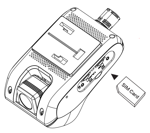
Ensure that the device is ACC OFF before attaching a proper SIM card.
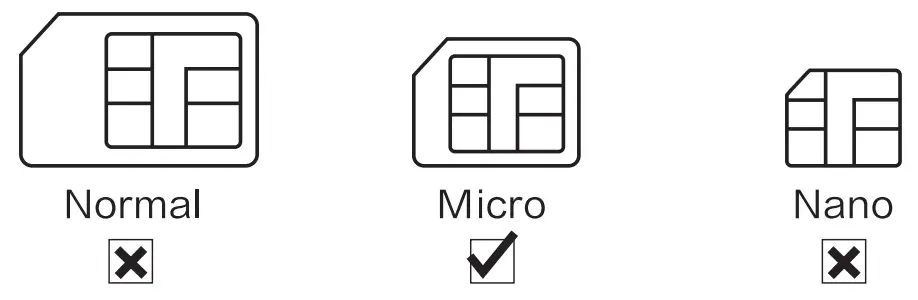
To attach and detach the SIM that may damage the contacts, please use the completed Micro SIM card instead. In addition, the SIM should have data service activated and not in arrears.
![]() Note: Refer to 3.2 for the SIM sizeFit the SIM in the correct slot.
Note: Refer to 3.2 for the SIM sizeFit the SIM in the correct slot.
 3.3 TF Card AttachmentEnsure that the device is ACC OFF before attaching a proper TF card.
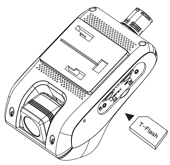
![]() Note
Note
- Use a TF card in speed class 10 or higher and with a capacity of 16GB or above.
- The TF card is recommended to change every half a year to ensure the recording performance of the device.
- Mount the tamper cover after the attachment.
Fit the TF card in the correct slot.
3.4 Main Unit Installation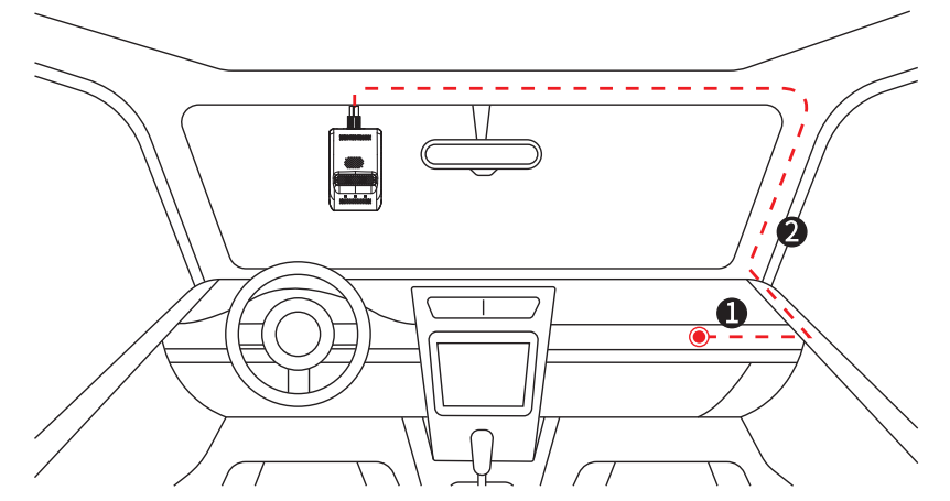
- Connect the power cable of the device to B+, ACC, and GND of the fuse box on the vehicle.
1is a reference position. - Route the power cable along the A-pillar of the vehicle to the upper center of the front windshield. The red dashed line
2in the figure is for reference.
- Select a proper installation position and wipe the position clean. Remove the protective film from the 3M tape of the mounting base and attach it to the position. Wait for 2 hours before proceeding to the next step. See
3for reference. - Mount the device to the base and connect its power cable correctly (see
4for reference). Then fasten the cable securely.

3.5 Installation of Accessories
You can select a proper position to install the remote camera according to actual conditions.3.5.1 Remote AHD Camera
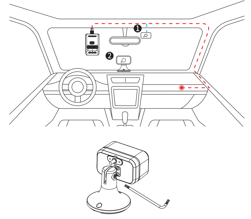
- Face the camera inward and install it to the windshield behind the rear-view mirror (as shown in
1) or to the middle of the dashboard (as shown in2). Wipe a selected position clean, remove the protective film from the 3M tape, and attach the device. - Use the supplied screwdriver to tighten the screw of the camera, so it keeps at the best angle. Connect the cables correctly and fasten them securely.
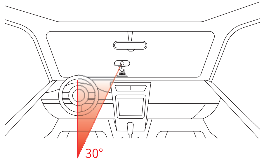
3.5.2 DMS CameraThis section is dedicated to JC400D.The DMS camera is mainly used for monitoring the driver. Fixate the camera at an angle about 30° to the steering wheel directly facing the driver’s head, as the following figure shows.
 3.5.3 Other Accessories

- External batteryIt is used to power the device for a while after its main supply is cut off. Connect the external battery to the corresponding interface on the device and place it in a proper position (such as 0 in the above figure).
- SOS keyIt is used to seek help in emergencies. Connect the SOS key to the corresponding interface on the device, remove the protective film from the 3M tape, and then attach it to a proper position (such as 0 in the above figure).
- RelayIt is used to cut off the power and fuel of the vehicle remotely to force it to stop. Connect it to the corresponding interface on the device and place it in a proper position, such in the above figure. For wiring details, see 1.4.
- RS232 (optional)It is used to connect to an external device for function expansion when a scenario requires a feature that cannot be offered by the device.
4is a reference installation position.
![]() Note:
Note:
- Choose proper accessories based on your actual needs.
- Select a relay that goes perfectly with the battery of your vehicle.
- 1t is recommended to ask a distributor, a designated business, or an expert to do the installation and commissioning.
3.6 Commissioning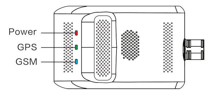
- Check the LED: See 1.3.3 for reference.
- Check the camera: The camera works correctly if you can view the live video of the camera and switch between the two cameras after logging in to the platform. You can also manually adjust the camera according to your needs.

Platform Operations
4.1 Installation4.1.1 Platform
Scan the QR code on the right with the browser of your mobile phone to download and install the app.
4.1.2 Calibration Tool for JC400D
 https://resadmin.blob.core.windows.net/other/dms.apk
Scan the QR code on the left with the browser of your mobile phone to download and install the calibration tool.
![]() Note:This app is used for feature calibration of JC400D.This calibration tool is only compatible with mobiles with Android OS.
Note:This app is used for feature calibration of JC400D.This calibration tool is only compatible with mobiles with Android OS.
4.2 Operation Guide
 https://www.jimilab.com/upfilesimg/file/15965223110.pdf
Scan the QR code on the right with the browser of your mobile phone to view relevant operations.
- Others
report this ad5.1 Battery Safety
- Use the original battery supplied by the manufacturer only. The use of any non-original accessories may damage the device, in which case the manufacturer will assume no repair liabilities for such damages.
- Avoid metal objects as they may cause short circuits on battery contacts.
- Do not remove the cover of the battery.
- Do not soak the battery in water or expose it to fire.
- it is forbidden to use batteries that are deformed, discolored, spilled, or package-damaged. If such an exception, such as over-temperature, deformation, discoloration, spillage, etc., occurs during use, charging, or storage of the battery, please stop using the device immediately and contact the aftersales center for a replacement.
- it is forbidden to dismantle or modify, or charge (in any other method other than stated) the battery.
[xyz-ips snippet=”download-snippet”]