NAVICCX0540 Rev 00.4 Automated Steerable Scanner
SAFETY WARNINGS / PRECAUTIONSKEEP THIS MANUAL DO NOT LOSE THIS MANUAL IS PART OF THE NAVIC SYSTEM AND MUST BE RETAINED FOR THELIFE OF THE PRODUCT. PASS ON TO SUBSEQUENT OWNERS. Ensure any amendments are incorporated with this document.WARNING! The NAVIC is designed for a specific use. Using theNAVIC outside of its intended use is dangerous. Failure to comply with the warnings, instructions, and specifications in this manual could result in SEVERE INJURY or DEATH. Read and understand this manual before using.WARNING! FALLING OBJECT HAZARD. The area below acrawler must be kept clear at all times. A clearly marked NO ENTRY ZONE must be cordoned off directly below the area of crawler operation. (see “Preparation for Safe Use” on page 40 for additional details)WARNING! Do NOT operate or place crawler on a surface higherthan 2 m (6 ft) without a proper tether held taut at all times. (see “Tether Requirements and Attachment” on page 41 for additional details)WARNING! ELECTRICAL CORDS CAN BE HAZARDOUS.Misuse can result in FIRE or DEATH by ELECTRICAL SHOCK. Inspect thoroughly before each use. Do NOT use if damaged. Do NOT use when wet. Keep away from water. Do NOT drive, drag or place objects over cord.WARNING! Do NOT operate scanner in an explosive environment.Do NOT operate scanner in the presence of volatile substances.
PAGE i of xi
CX0540 Rev 00.4
WARNING! MAGNETIC MATERIAL. The wheels of the crawlerproduce an extremely strong magnetic field which may cause failure or permanent damage to items such as watches, memory devices, CRT monitors, medical devices or other electronics. Tools, magnets and metal objects can cut, pinch or entrap hands and fingers. HANDLE WITH CARE. People with pacemakers or ICD’s must stay at least 75 cm (30 in) away.WARNING! MAGNETIC MATERIAL. The handheld controllerproduces a strong magnetic field which may cause failure or permanent damage to items such as watches, memory devices, CRT monitors, medical devices or other electronics. People with pacemakers or ICD’s must stay at least 10 cm (4 in) away.WARNING! MAGNETIC MATERIAL. When the carrying casecontains the crawler, a magnetic field exists outside the case which may cause failure or permanent damage to items such as watches, memory devices, CRT monitors, medical devices or other electronics. People with pacemakers or ICD’s must stay at least 10 cm (4 in) away from the carrying case when it contains the crawler.WARNING! MAGNETIC MATERIAL. The installation/removal mat(see “Scanner Installation/Removal Mat Use” on page 132) contains magnetic material. People with pacemakers or ICD’s must stay at least 10 cm (4 in) away.WARNING! LASER RADIATION. The battery powered opticalguide contains a Class 1M laser. Do not view directly with optical instruments.WARNING! If this product is to be used with any Child Productslisted in (Chaper 2.3), be sure to read and comply with the warnings, instructions, and specifications in the Child Product’s User Manual(s).WARNING! DO NOT DISASSEMBLE. No user-serviceable parts.Disassembling any of the components in this product, beyond the instructions in this user manual, could void the regulatory certifications and/or effect the safety of the product.PAGE ii of xi
CAUTION! Pinch points exist with this product. Keep fingers andhands clear of pinch points.CAUTION! Do NOT operate the NAVIC crawler on an inspectionsurface which is electrically connected to a component that is being welded.CAUTION! DO NOT DISCONNECT UNDER LOAD. Shut off powerbefore connecting or disconnecting. Permanent damage to electronics could occur.EMERGENCY STOP. This symbol indicates emergency stop button.The WEEE symbol indicates that the product must not be disposed of as unsorted municipal waste, but should be collected separately. (see “Disposal” on page 182 for additional details)
PAGE iii of xi
CX0540 Rev 00.4
TABLE OF CONTENTS
Identification 1Chapter1.1. Product Brand
1 1
1.2. Manufacturer
1
1.3. Compliance Declarations
1
1.3.1.ISED Emissions Compliance (Canada)
1
1.3.2.FCC Suppliers Declaration of Conformity (United States)
1
1.3.3.European Union CE Declarations
2
1.3.4.UKCA Declarations
2
Product Specifications 2Chapter2.1. Base NAVIC System
3 3
2.1.1.Intended Use
3
2.1.1.1Operating Limits
4
2.1.1.2Operating Environment
5
2.1.1.3User
5
2.1.2.Unintended Use
5
2.1.3.Dimensions and Weight
6
2.1.4.Power Requirements
8
2.1.5.Environmental Sealing
8
2.1.6.Performance Specifications
8
2.1.7.Encoder Interface Specifications
9
2.2. Compatible Components
10
2.2.1.Low Profile Probe Holder Frame
10
2.2.1.1Intended Use
10
2.2.1.2Operating Limits
10
2.2.2.Vertical Probe Holder Frame
10
2.2.2.1Intended Use
10
2.2.2.2Operating Limits
10
2.2.3.Pivoting Probe Holder Frame
11
2.2.3.1Intended Use
11
PAGE iv of xi
2.3.
2.2.3.2Operating Limits 2.2.4.Frame Bar2.2.4.1Intended Use 2.2.4.2Operating Limits 2.2.5.Slip Joint Probe Holder 2.2.6.Vertical Probe Holder 2.2.7.Heavy Duty Vertical Probe Holder 2.2.8.Corrosion Thickness Probe Holder 2.2.9.HydroFORM Cart 2.2.10.Preamp Bracket 2.2.10.1Intended Use 2.2.10.2Operating Limits 2.2.11.NAVIC Backpack 2.2.11.1Intended Use 2.2.11.2Operating Limits 2.2.12.NAVIC Camera Mount 2.2.12.1Intended Use 2.2.12.2Operating Limits 2.2.13.Battery Powered Optical Guide 2.2.13.1Intended Use 2.2.13.2Operating Environment 2.2.13.3Power Requirements 2.2.13.4Environmental Sealing 2.2.14.Medium Temperature Add-On Kit 2.2.14.1Intended Use 2.2.14.2Operating Limits 2.2.15.Encoder Adapter 2.2.15.1Intended Use 2.2.16.3-Axis Nozzle Scanner Add-On KitChild Products2.3.1.Motorized Couplant Pump 2.3.2.Motorized Raster Arm 2.3.3.Actuated Probe Lift 2.3.4.Preamp 2.3.5.Optical Guide 2.3.6.Tracker 2.3.7.Battery Kit
Definitions 3Chapter3.1. Definition of Symbols 3.2. Definitions of Terms 3.3. Safety Symbols 3.4. Safety Signal Words
PAGE v of xi
11 11 11 11 12 12 12 12 12 13 13 13 13 13 13 14 14 14 14 14 14 14 14 15 15 15 15 15 15 16 16 16 16 16 17 17 171818 18 19 19CX0540 Rev 00.4
System Components
20
4Chapter
4.1. Component Identification
20
4.1.1.Base System
20
4.1.2.Compatible Components
22
4.1.3.Child Products
24
4.2. Tools
25
4.2.1.Included Tools
25
4.2.2.Optional Tools
25
4.3. Base System Components
26
4.3.1.Crawler
26
4.3.1.1Right Drive Module
26
4.3.1.1.1Encoder
27
4.3.1.2Left Drive Module
27
4.3.2.Power Controller
28
4.3.2.1AC/DC Power Supply
29
4.3.3.Umbilical
30
4.3.3.1Umbilical Connections
30
4.3.3.2Emergency Stop Button
31
4.3.3.3Encoder Signal Isolation
32
4.3.4.Handheld Controller
32
4.3.5.Auxiliary Cable
33
4.3.6.J300 Encoder Cable
33
4.3.7.Installation/Removal Mat
34
4.3.8.Lifting Sling
34
4.3.9.Irrigation Kit
34
4.3.10.Cable Management
34
4.3.11.Cap & Plug
35
4.3.12.Tools
35
4.3.13.Cases
35
4.4. Compatible Components
35
4.4.1.Low Profile Probe Holder Frame
35
4.4.2.Vertical Probe Holder Frame
35
4.4.3.Pivoting Probe Holder Frame
35
4.4.4.Frame Bar
36
4.4.5.Slip Joint Probe Holder
36
4.4.6.Vertical Probe Holder
36
4.4.7.Heavy Duty Vertical Probe Holder
36
4.4.8.Corrosion Thickness Probe Holder
36
4.4.9.HydroFORM Cart
37
4.4.10.Preamp Bracket
37
4.4.11.NAVIC Backpack
37
4.4.12.NAVIC Camera Mount
37
PAGE vi of xi
4.4.13.Battery Powered Optical Guide 4.4.14.Automated Crawler Medium Temperature Add-On Kit 4.4.15.Encoder Adapter 4.4.16.3-Axis Nozzle Scanner Add-On Kit4.5. Child Products4.5.1.Motorized Couplant Pump 4.5.2.Motorized Raster Arm 4.5.3.Actuated Probe Lift 4.5.4.Preamp 4.5.5.Optical Guide 4.5.6.Tracker 4.5.7.Battery Kit
Preparation for Use
40
5Chapter
5.1. Preparation for Transportation
5.2. Preparation for Safe Use
5.2.1.No Entry Fall Zone
5.2.2.Tether Requirements and Attachment
5.2.3.Lifting Sling Setup
5.2.4.Lifting Sling Low Profile Setup5.3. Preparation of Inspection Surface 5.4. System Connectivity 5.5. Configurations
5.5.1.Single Drive Module with Frame Bar
5.5.2.Crawler with Actuated Probe Lift
5.5.3.Crawler with Multiple Probe Holders
5.5.3.1Vertical Probe Holder Frame
5.5.3.2Low Profile Probe Holder Frame
5.5.3.3Pivoting Probe Holder Frame
5.5.3.4Flange5.5.4.3-Axis Nozzle Scanning5.6. Right Drive Module
5.6.1.Swivel Mount
5.6.2.Umbilical
5.6.3.Handle
5.6.4.Dovetail Accessory Mount5.7. Left Drive Module
5.7.1.Swivel Mount
5.7.2.Umbilical Connection
5.7.3.Handle
5.7.4.Dovetail Accessory Mount
PAGE vii of xi
37 38 38 38 38 38 38 39 39 39 39 3940 40 40 41 42 44 44 45 47 47 49 51 51 53 55 57 59 61 61 62 64 65 66 66 67 67 67CX0540 Rev 00.4
5.8. Handheld Controller
68
5.8.1.Magnetic Mounts
68
5.8.2.Connecting/Disconnecting Left and Right Modules
69
5.8.3.Probe Holders
71
5.8.4.Vertical Probe Holder
71
5.8.4.1Probe Holder Setup
71
5.8.4.2Probe Holder Vertical Adjustment
72
5.8.4.3Probe Holder Transverse Adjustment
73
5.8.4.4Probe Holder Longitudinal Adjustment
74
5.8.4.5Probe Holder Left/Right Conversion
75
5.8.5.Slip Joint Probe Holder
77
5.8.5.1Probe Holder Setup
77
5.8.5.2Probe Holder Adjustment
79
5.8.5.3Probe Holder Force Adjustment
80
5.8.5.4Slip Joint Probe Holder Left/Right Conversion
82
5.8.6.Heavy Duty Vertical Probe Holder
84
5.8.6.1Probe Holder Setup
84
5.8.6.2Probe Holder Vertical Adjustment
86
5.8.6.3Probe Holder Left/Right Conversion
86
5.8.6.4Probe Holder 90° Adjustment
88
5.9. 3-Axis Nozzle Scanning
89
5.9.1.Scanner Preparation
89
5.9.2.3-Axis Nozzle Operation
94
5.9.3.Encoded Skew Vertical Probe Holder
98
5.9.4.Probe Holder Setup
98
5.9.5.Skew Encoder Cable
100
5.9.6.Encoded Skew Vertical Probe Holder Adjustment
100
5.9.6.1Latch Pin
101
5.9.7.Skew Angle Adjustment
102
5.9.7.1Ratchet Lever
103
5.9.8.Pivot Buttons
103
5.9.9. Cable Clips
104
5.10. Slider PPS
105
5.10.1.Slider PPS Encoder
107
5.11. Probe Holder Frames
108
5.11.1.Vertical Probe Holder Frame – Flat or Circumferential Only
108
5.11.2.Low Profile Probe Holder Frame – Flat or Circumferential Only
112
5.11.3.Pivoting Probe Holder Frame
116
5.11.3.1Mounting a Pivoting Probe Holder Frame
117
5.11.3.2Pivoting Probe Holder Frame Setup – Longitudinal Scanning
118
5.11.3.3 Pivoting Probe Holder Frame – Circumferential Scanning
119
5.11.3.4Pivoting Probe Holder Frame – Flange Scanning
120
5.11.3.5Optical Guide Pivot Mount
122
PAGE viii of xi
5.12.
Accessories5.12.1.Battery Powered Optical Guide 5.12.2.Cable Management5.12.2.1Mounting Cable Management 5.12.2.2Cable Management Setup 5.12.2.3Clamp Setup 5.12.3.NAVIC Backpack 5.12.4.Preamp Bracket 5.12.4.1Mounting Preamp Bracket 5.12.4.2Attaching Preamp with Screws 5.12.4.3Attaching Preamp with Velcro Straps
Operation
129
6Chapter
6.1. System Startup
6.2. Placement of Crawler on Inspection Surface
6.2.1.Scanner Installation/Removal Mat Use6.3. Operation
6.3.1.Handheld Controller Layout
6.3.1.1Touchscreen 6.3.1.2D-pad 6.3.1.3Joysticks 6.3.2.Mode Select Screen
6.3.3.Jog Mode
6.3.4.Latched Jog Mode
6.3.5.1 Axis Scan Mode
6.3.5.11 Axis Scan Screen 6.3.6.System Utilities Screen
6.3.6.1User Settings Screen 6.3.6.2Diagnostics Screens6.3.6.2.1Detected Modules 6.3.6.2.2System 1 6.3.6.2.3System 2 6.3.6.2.4System 3 6.3.6.2.5LeftDrv, Right Drv, 6.3.6.3Touch Calibration Screen 6.3.6.4Joystick Calibration Screen 6.3.6.5Draw 6.3.7.High Internal Temperature Screen
Maintenance
151
7Chapter
7.1. Safety Precautions Before Maintenance
7.2. Cleaning
7.3. Maintenance Schedule
PAGE ix of xi
123 123 124 124 124 125 126 127 127 127 128129 131 132 134 134 135 135 135 136 136 138 139 140 142 143 144144 145 145 146 146 147 148 149 149151 151 152CX0540 Rev 00.4
Troubleshooting 8Chapter8.1. Startup Issues
153 153
8.1.1.Joystick Off Center
153
8.1.2.Checking Network
153
8.2. Startup Override
154
8.2.1.Scan Devices
155
8.2.2.Reset Parameters
156
8.2.3.System Parameters
156
8.2.4.Device Address
156
8.3. Encoder Failure
157
8.4. Umbilical Troubleshooting
158
8.5. Additional Issues
158
8.6. Retrieval of a Stranded Crawler
159
Service and Repair 9Chapter9.1. Technical Support
160 160
Spare Parts 1 0 Chapter10.1. Crawler
161 161
10.2. Kit Components
162
10.2.1.Encoder Connector Type
164
10.2.2.Power Cord Type
164
10.3. Cable Management
165
10.3.1.Cable Management Sleeving
165
10.4. Probe Holder Frame
166
10.5. Low Profile Probe Holder Frame
167
10.6. Pivoting Probe Holder Frame
168
10.7. Slip Joint Probe Holder Parts
169
10.8. Vertical Probe Holder Parts
170
10.9. Heavy Duty Vertical Probe Holder
171
10.10. Corrosion Thickness Probe Holder
172
10.11. Encoded Skew Vertical Probe Holder
173
10.12. 3-Axis Nozzle Scanner Add-On Kit
174
10.12.1. Slider PPS Encoded Leadscrew
175
10.13. Probe Holder Components
175
10.13.1.Arm Style
175
10.13.2.Yoke Style
175
10.13.3.Swing Arm Style
175
10.13.4.Heavy Duty Yoke Style
175
PAGE x of xi
10.13.5.Pivot Button Style
176
10.14. Probe Holder Receptacle and Wear Plate
176
10.15. Variable Components
177
10.15.1.Frame Bar
177
10.15.2.Automated Crawler Medium Temperature Add-On Kit
178
10.16. Accessories
179
10.16.1.Preamp Bracket
179
10.16.2.NAVIC Backpack
179
10.16.3.Battery Powered Optical Guide
180
10.17. Cases
181
Disposal 11Chapter
182
Limited Warranty
183
12Chapter
PAGE xi of xi
CX0540 Rev 00.4
Chapter 1IDENTIFICATION1.1. Product BrandThis user manual describes the proper safety precautions, setup and use of the NAVIC system.
1.2. ManufacturerDistributor:
Manufacturer:Jireh Industries Ltd.53158 Range Road 224 Ardrossan, Alberta, Canada T8E 2KPhone: 780.922.4534jireh.com
1.3. Compliance Declarations
1.3.1.
ISED Emissions Compliance (Canada)CAN ICES-003(A) / NMB-003(A) This Class A digital apparatus complies with Canadian ICES-003. Cet appareil numérique de la classe A est conforme à la norme NMB-003 du Canada.
1.3.2.
FCC Suppliers Declaration of Conformity (United States)This device complies with Part 15 of the FCC Rules. Operation is subject to the following two conditions: (1) this device may not cause harmful interference, and (2) this device must accept any interference received, including interference that may cause undesired operation.This equipment has been tested and found to comply with the limits for a Class A digital device, pursuant to part 15 of the FCC Rules. These limits are designed to provide reasonable protection against harmful interference when the equipment is operated in a commercial environment. This equipment generates, uses, and can radiate radio frequency energy and, if not installed and used in accordance with the instruction manual, may cause harmful interference to radio communications. Operation of this equipment in a residential area is likely to cause harmful interference in which case the user will be required to correct the interference at his own expense.
PAGE 1 of 184
CX0540 Rev 00.4
RESPONSIBLE PARTY NAME: ADDRESS:TELEPHONE:
Jireh Industries2955 S Sam Houston Pkwy E Suite 300 Houston, Texas United States 77047832-564-0626
1.3.3.
European Union CE DeclarationsJireh Industries hereby declares that the NAVIC product complies with the essential requirements and other relevant provisions of the following European Union directives: 2014/30/EU EMC Directive 2014/35/EU Low Voltage Directive 2012/19/EU Directive on Waste Electrical and Electronic Equipment 2011/65/EU Directive on Restriction of Hazardous Substances (RoHS)
1.3.4.
UKCA DeclarationsJireh Industries hereby declares that the NAVIC product complies with the essential requirements and other relevant provisions of the following UK directives.
Title
Edition/Date of Issue
Electromagnetic Compatibility Regulations
2016
Electrical Equipment (Safety) Regulations
2016
Waste Electrical and Electronic Equipment Regulations 2013
Restriction of the Use of Certain Hazardous Substances 2012 in Electrical and Electronic Equipment Regulations
PAGE 2 of 184
Chapter 2PRODUCT SPECIFICATIONS2.1. Base NAVIC SystemThis section outlines the product specifications of the base system. When the base system is used together with compatible components (Chapter 2.2) or child products (Chapter 2.3), the product specifications of the base system may be superseded. See (see “Compatible Components” on page 10) and (see “Child Products” on page 16).2.1.1. Intended UseWARNING! FALLING OBJECT HAZARD.The NAVIC is intended for a specific use. Read and understand the intended and unintended use limits below. Using the NAVIC outside of its intended use is dangerous and could result in SEVERE INJURY or DEATH.The NAVIC’s primary purpose is to perform inspections of ferrous assets such as pipes, vessels, or storage tanks by moving an inspection tool over a ferrous surface. It is intended for industrial use only.
PAGE 3 of 184
CX0540 Rev 00.4
2.1.1.1 Operating Limits
CategoryInspection Surface
Parameter Maximum coating thickness: Up-side-down orientation Vertical orientation Horizontal, Right-side-up orientation Condition
Minimum thicknessMinimum ID, internal circumferential drivingMinimum OD, external Circumferential drivingMinimum OD, longitudinal drivingMaximum surface temperature
SpecificationBare metal only 0.5 mm (0.020 in) 1 mm (0.040 in)Clean, free of excess rust, scale, debris (i.e. dirt, sand, etc.), ice, frost 3 mm (0.120 in) 610 mm (24 in)70 mm (2.75 in)305 mm (12 in)50°C (122°F)
Category Scanner
ParameterMaximum umbilical lengthMaximum payload (performance may vary with surface condition)
Specification30 m (100 ft)10 kg (23 lb) (Umbilical and attachments are considered payload)
AttachmentsOrientation while driving at height >2 m (6 ft) on vertical surface Required radial clearance (handles removed, circumferential driving)
Restricted to those listed in compatible components or child productsUmbilical strain relief to point downwards, or at worst, horizontal. It is not to point upwards70 mm (2.75 in) on outer diameters <200 mm (8 in) 81.5 mm (3.2 in) on outer diameters >200 mm (8 in)
PAGE 4 of 184
2.1.1.2 Operating EnvironmentThe NAVIC is for use in dry industrial environments having ambient temperatures shown below. It is NOT intended for use in explosive environments.
Category Parameter Environment Minimum ambient temperatureMaximum ambient temperature
Specification -20°C (-4°F) 50°C (122°F)*
* CAUTION! In some high temperature conditions, the surface temperatures may become too hot for prolonged touch. When operating with the maximum payload of 10 kg (23 lb) and at an ambient temperature of 50°C (122°F), reduce the operation to a 25% duty cycle with a maximum on time of 30 minutes to ensure safe surface temperatures. It is important that the operator be aware of the possibility of hot surfaces and utilize gloves when necessary.The NAVIC has built-in temperature protections for its electronics and will warn the operator and shut down before temperatures are reached, which might damage the system (see “High Internal Temperature Screen” on page 149).
2.1.1.3 UserThe NAVIC is intended to be used by persons who have read and understand the user manual. The intended user is to be a person without limitations in the physical abilities of the upper and lower limbs, sight, hearing, or anyone with a pacemaker.For operating at a height greater than 2 m (6 ft), the NAVIC is intended to be used by two people:1. a person who is trained in rigging and fall protection and is able to effectively apply the same safety principles to the crawler, and2. a person who is trained to operate the NAVIC
2.1.2.
Unintended UseThe NAVIC is NOT intended for: use outside of its intended use lifting / lowering objects or people (i.e. using the Navic as a crane / elevator) driving into / over obstructions, excluding standard weld caps installation on a surface on which welding is actively occurring In addition to the above points, for operating at a height greater than 2 m (6 in), the crawler is NOT intended for: operation without a proper tether system
PAGE 5 of 184
CX0540 Rev 00.4
operating up-side-downoperating while oriented such that the umbilical strain relief points upward (front for the Navic is lower than the umbilical connection).
2.1.3. Dimensions and WeightCrawler height: Crawler width: Crawler depth: Crawler height (handles removed): Crawler width (right drive module): Crawler weight: * Crawler weight (right drive module):
12.5 cm 28.2 cm 30.8 cm 8.1 cm 16.1 cm 7.7 kg 4.2 kg
4.9 in 11.1 in 12.1 in 3.2 in 6.3 in 17 lb 9.3 lb
30.8 cm (12.1 in)Fig. 1 – Crawler dimensions
PAGE 6 of 184
8.1 cm (3.2 in)
28.2 cm (11.1 in)Fig. 2 – Dual module dimensions
12.5 cm (4.9 in)
8.1 cm (3.2 in)16.1 cm (6.3 in)Fig. 3 – Single module dimensions * Dual module configuration excluding case, attachments, umbilical, power controller and handheld controller.
PAGE 7 of 184
CX0540 Rev 00.4
2.1.4. Power RequirementsWARNING! A reliable power source must beused to power the crawler. Connections must be secured to prevent accidental disconnection. Power failure may cause the crawler to freewheel down when operating in a vertical orientation. Portable generator usage is not recommended unless accompanied by the use of an uninterruptible power supply.WARNING! Proper grounding of the powersupply is important for safe operation. When a generator is used to supply power to the system (not recommended), the generator must be properly grounded (refer to generator manual).CAUTION! DO NOT DISCONNECT UNDERLOAD. Shut off power before connection or disconnecting. Permanent damage to electronics could occur.CAUTION! Power must be supplied from anapproved Jireh power source.
Input Voltage: Input Power:
25-45VDC 320 W
2.1.5. Environmental SealingDust-tight, watertight (not submersible).
2.1.6. Performance Specifications
Category Crawler
ParameterMaximum speedEncoder resolution, right module (idler encoder) Encoder resolution, left module (motor encoder)
Specification25 cm/sec (10 in/sec)13.78 counts/mm (349.9 counts/in) 872.5 counts/mm (22161.8 counts/in)
PAGE 8 of 184
2.1.7.
Encoder Interface SpecificationsOutput type: 4 channel quadrature 5VDC RS422 compatible.Power: Power must be supplied to the interface. 5VDC +/-10% power limited to < 15w.
1 Enc B 2 Enc B’ 3 Enc A 4 Enc A’ 5 Aux Enc A’ 6 Aux Enc A 7 Aux Enc B’ 8 Aux Enc B 9 Enc +5V 10 Enc Com H Shield
1
2
9
7
3
10
6
4
5
Fig. 4 – JIREH Industries pin out configuration
PAGE 9 of 184
CX0540 Rev 00.4
2.2. Compatible ComponentsThe components listed in this section integrate with the base system to perform certain tasks. Their use may modify the product specifications (i.e. intended use, power requirements, etc.) from those of the base system. The specifications listed here supersede those of the base system. If no specifications are listed here, the specifications of the base system remain effective.2.2.1. Low Profile Probe Holder Frame CXG004-
2.2.1.1 Intended Use
The Low Profile Probe Holder Frame is
intended to be mounted in the NAVIC’s swivel
mount to provide mounting of multiple probe holders. Its use limits the NAVIC’s operation
Fig. 5 – Low profile probe holder frame
to inspection surfaces that are either flat or driven on, in the circumferential
direction.
2.2.1.2 Operating Limits
Category Inspection SurfaceMaximum number of probe holders
ParameterMinimum OD, longitudinal drivingSlip joint probe holders
Specification Not recommended4
2.2.2. Vertical Probe Holder Frame CXG007-
2.2.2.1
Intended Use
The Vertical Probe Holder Frame is intended
to be mounted in the NAVIC’s swivel mount to
provide mounting of multiple probe holders. Its
use limits the NAVIC’s operation to inspection
Fig. 6 – Vertical probe holder frame
surfaces that are either flat or driven on, in the circumferential direction.
2.2.2.2 Operating Limits
Category Inspection SurfaceMaximum number of probe holders
ParameterMinimum OD, longitudinal drivingVertical probe holders
Specification Not recommended6
PAGE 10 of 184
2.2.3. Pivoting Probe Holder Frame CXG013-
2.2.3.1
Intended UseThe Pivoting Probe Holder Frame is intended to be mounted in the NAVIC’s swivel mount to provide mounting of multiple probe holders. Its use limits the NAVIC’s operation to the operating limits shown below.
Fig. 7 – Pivoting probe holder frame
2.2.3.2 Operating Limits
Category Inspection SurfaceMaximum number of probe holders
ParameterMinimum OD, longitudinal driving Vertical probe holders
Specification 305 mm (12 in)6
2.2.4. Frame Bar BG0038-
2.2.4.1 Intended Use
The Frame Bar is intended to be mounted in
the NAVIC’s swivel mount to provide mounting
of multiple probe holders. Its use limits the NAVIC’s operation to inspection surfaces that
Fig. 8 – Frame bar
are either flat or driven on in the circumferential direction.
2.2.4.2 Operating Limits
Category Inspection SurfaceMaximum number of probe holders
ParameterMinimum OD, longitudinal driving Slip joint probe holdersVertical probe holdersHeavy duty vertical probe holders
Specification Not recommended2 2 2
PAGE 11 of 184
CX0540 Rev 00.4
2.2.5.
Slip Joint Probe Holder PHA012-The Slip Joint Probe Holder is intended to provide a probe holding solution for probes and wedges with pivot button holes. It is useful for situations requiring a lower profile. It is mounted in the dovetail groove of any probe holder frame or frame bar.
Fig. 9 – Slip joint probe holder
2.2.6.
Vertical Probe Holder PHA015-The Vertical Probe Holder is intended to provide a probe holding solution for probes and wedges with pivot button holes. It is mounted in the dovetail groove of any probe holder frame or frame bar.
2.2.7.
Heavy Duty Vertical Probe Holder PHS043-The Heavy Duty Vertical Probe Holder is intended to provide a probe holding solution for larger, heavier probes. It is mounted in the dovetail groove of any probe holder frame or frame bar.
Fig. 10 – Vertical probe holder
2.2.8.
Corrosion Thickness Probe Holder PHS046- / PHS056-The Corrosion Thickness Probe Holder is intended to provide a probe holding solution for specific probes or wedges that do not have pivot button holes. It is mounted in the dovetail groove of any probe holder frame or frame bar.
Fig. 11 – Heavy duty vertical probe holder Fig. 12 – Corrosion thickness probe holder
2.2.9.
HydroFORM Cart PHS044The HydroFORM Cart is intended to provide a solution for holding the Olympus HydroFORM probe. It is used in conjunction with the heavy duty vertical probe holder.
Fig. 13 – HydroFORM cart
PAGE 12 of 184
2.2.10. Preamp Bracket CES029-
2.2.10.1 Intended Use
The Preamp Bracket is intended to mount
objects such as preamps, splitters, etc. on
a probe holder frame or frame bar that is mounted to the NAVIC crawler. The mounted
Fig. 14 – Preamp bracket
object is attached to the NAVIC with a lanyard or probe cables strong enough
to prevent the object from falling, should the straps or screws that hold it to
the bracket fail. Also, if the object is mounted with straps, it is to have smooth
edges so as not to cut the straps.
2.2.10.2 Operating Limits Category Preamp BracketScanner
Parameter
Specification
Maximum weight of mounted objectRequired radial clearance (handles removed, circumferential driving)
1.36 kg (3 lb)Dependent on object mounted on Preamp Bracket
2.2.11. NAVIC Backpack CXS077
2.2.11.1 Intended Use
The NAVIC Backpack is intended to mount
objects such as preamps, splitters, etc. on the
NAVIC crawler. The mounted object is to be attached to the NAVIC with a lanyard or probe
Fig. 15 – NAVIC backpack
cables strong enough to prevent the object from falling, should the straps fail.
Also, the object is to have smooth edges so as not to cut the strap.
2.2.11.2 Operating Limits Category NAVIC BackpackScanner
ParameterMaximum weight of mounted objectRequired radial clearance
Specification 1.36 kg (3 lb)Dependent on object mounted to Backpack
PAGE 13 of 184
CX0540 Rev 00.4
2.2.12. NAVIC Camera Mount CXG067
2.2.12.1
Intended UseThe NAVIC Camera Mount is intended to mount any small action camera on the NAVIC crawler.
2.2.12.2 Operating Limits
Fig. 16 – NAVIC camera mount
Category CameraScanner
ParameterMaximum weightRequired mounting hole Required radial clearance
Specification 0.5 kg (1.1 lb) 1/4 in – 20 threadDependent on camera size
2.2.13. Battery Powered Optical Guide CXS080
2.2.13.1 Intended Use
The Battery Powered Optical Guide is
intended to provide a point of reference useful
for guiding the NAVIC along a given path (i.e. a weld cap). It is intended to be mounted in
Fig. 17 – Battery powered optical guide
the dovetail groove of any probe holder frame or frame bar.
2.2.13.2 Operating Environment Category Scanner
ParameterRequired radial clearance
SpecificationDependent on mounted orientation of Battery Powered Optical Guide
2.2.13.3 Power Requirements Power requirements: 1 AA battery2.2.13.4 Environmental Sealing IP64
PAGE 14 of 184
2.2.14. Medium Temperature Add-On Kit CXG031-
2.2.14.1
Intended UseThe Medium Temperature Add-On Kit allows the NAVIC to operate on inspection surfaces that are hotter.
2.2.14.2 Operating Limits
Fig. 18 – Automated crawler medium temperature add-on kit
Category Inspection surfaceScanner
ParameterMaximum surface temperatureRequired radial clearance
Specification 150°C (302°F)Dependent on object mounted to Backpack
2.2.15. Encoder Adapter UMA010-
2.2.15.1
Intended UseThe Encoder Adapter adapts a scanner’s existing encoder cable connector to a different instrument’s encoder input.
2.2.16.
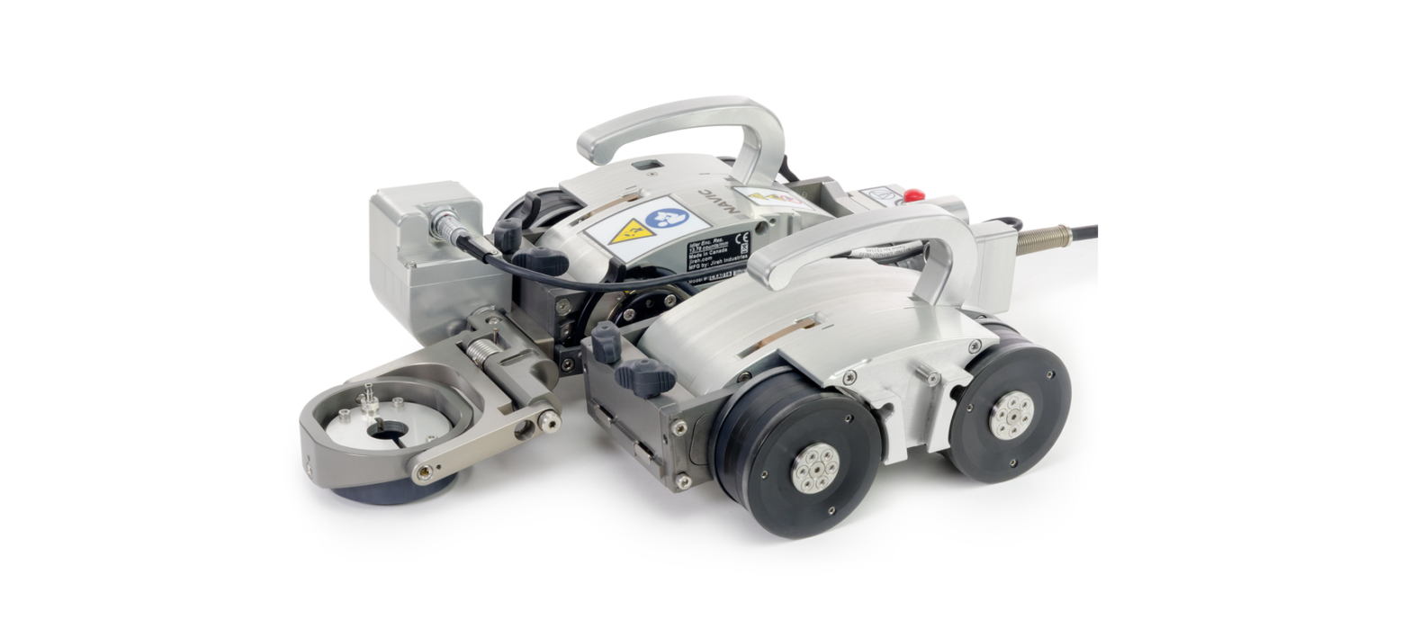
3-Axis Nozzle Scanner Add-On Kit CXG028-Mounted on a single NAVIC pod, the 3-axis nozzle scanner add-on kit includes a specialized probe holding system for inspection of nozzle and fitting welds.
Fig. 19 – Encoder adapter
Fig. 20 – 3-axis nozzle scanner add-on kit
PAGE 15 of 184
CX0540 Rev 00.4
2.3. Child ProductsThe products listed in this section integrate with the base system to perform certain tasks. Their use may modify the product specifications (i.e. intended use, power requirements, etc.) from those of the base system. These products have a user manual of their own, and shall be referred to for their product specifications as well as how their use modifies the product specifications of the base system.
2.3.1.
Motorized Couplant Pump CMA015The Motorized Couplant Pump is a powered pumping unit used to supply couplant fluid to scanning equipment.
2.3.2.
Motorized Raster Arm CWG002-Available in various lengths, the Motorized Raster Arm can carry many different probes for various types of corrosion scans. The Motorized Raster Arm is intended to be mounted in the NAVIC’s swivel mount.
2.3.3.
Actuated Probe Lift CXG030-The Actuated Probe Lift allows the user to raise and lower a corrosion thickness probe holder remotely from the handheld controller. This allows the probe to avoid obstacles and large welds, preventing damage and unnecessary wear to the probe. The Actuated Probe Lift is intended to be mounted in the NAVIC’s swivel mount.
2.3.4.
Preamp CXG032The Preamp is used to amplify the return signal from an ultrasonic transducer and improve the signal-to-noise ratio for transmission over long cables.
Fig. 21 – Motorized couplant pump Fig. 22 – Motorized raster arm Fig. 23 – Actuated probe lift Fig. 24 – Preamp
PAGE 16 of 184
2.3.5.
Optical Guide CXG035The Optical Guide mount’s to any dovetail attached to a motorized crawler. The Optical Guide provides a green colour, point of reference for guiding scanners along a given path (i.e. a weld).
2.3.6.
Tracker DRG001The Tracker uses advanced laser guidance to follow elevated profiles (i.e. a weld) on a ferrous surface. It is intended to be mounted in the dovetail groove of any probe holder frame or frame bar.
2.3.7.
Battery Kit DVG001-The battery provides portable power to the crawler.
Fig. 25 – Optical guide Fig. 26 – Tracker
Fig. 27 – Battery
PAGE 17 of 184
CX0540 Rev 00.4
Chapter 3DEFINITIONS3.1. Definition of SymbolsInstructions to `look here’ or to `see this part’.Denotes movement. Instructing user to carry out an action in a specified direction. Indicates alignment axis Alerts the user that the view has changed to a reverse angle3.2. Definitions of Terms
Fig. 28 – Circumferential scanning
Fig. 29 – Longitudinal scanning
Circumferential Longitudinal
Direction of scan travel is around the circumference of the pipe/tube (Fig. 28).Direction of scan travel is lengthwise of the pipe/tube (Fig. 29).
PAGE 18 of 184
3.3. Safety SymbolsThe following safety symbols might appear on the product and in this document. Read and understand their meaning below:
General warning symbolShock hazard caution symbolLaser warning symbol
This symbol is used to alert the user to potential hazards. All safety messages that follow this symbol shall be obeyed to avoid possible harm or material damage.This symbol is used to alert the user to potential electric shock hazards. All safety messages that follow this symbol shall be obeyed to avoid possible harm.This symbol is used to alert the user to potential laser hazards. All safety messages that follow this symbol shall be obeyed to avoid possible harm or material damage.
3.4. Safety Signal WordsThe following safety signal words might appear in this document. Read and understand their meaning below:
DANGER! WARNING! CAUTION!
The DANGER signal word indicates an imminently hazardous situation. It calls attention to a procedure, practice, or the like that if not correctly performed or adhered to will result in death or serious personal injury. Do not proceed beyond a DANGER signal word until the indicated conditions are fully understood and met.The WARNING signal word indicates a potentially hazardous situation. It calls attention to a procedure, practice, or the like that if not correctly performed or adhered to could result in death or serious personal injury. Do not proceed beyond a WARNING signal word until the indicated conditions are fully understood and met.The CAUTION signal word indicates a potentially hazardous situation. It calls attention to a procedure, practice, or the like that if not correctly performed or adhered to may result in minor or moderate personal injury, material damage, particularly to the product, destruction of part or all of the product, or loss of data. Do not proceed beyond a CAUTION signal word until the indicated conditions are fully understood and met.
PAGE 19 of 184
CX0540 Rev 00.4
Chapter 4SYSTEM COMPONENTS4.1. Component Identification4.1.1. Base System
Fig. 30 – NAVIC (crawler) CXA016-
Fig. 31 – Power controller CXA040-
Fig. 32 – Umbilical UMA030-
Fig. 33 – Handheld controller DMA006
Fig. 34 – Auxiliary cable UMA017-06
Fig. 35 – J300 Encoder cable UMA025-
Fig. 36 – Installation/removal mat AAS061
Fig. 37 – Lifting sling CXA009
Fig. 38 – Irrigation kit CMG009-
Fig. 39 – Cable management CXS046-
Fig. 40 – Cap: NAVIC hinge cover CXS066PAGE 20 of 184
Fig. 41 – Plug CX0174
Fig. 42 – 3 mm hex driver EA414
Fig. 43 – 3/8 in wrench EA470
Fig. 44 – 3 mm flat driver EA480
Fig. 45 – Case, NAVIC crawler CXA044
Fig. 46 – Umbilical/probe holder frame case CXA023
Fig. 47 – Umbilical case EA421
Fig. 48 – Motorized pump / umbilical case CMA016
Fig. 49 – Motorized pump / umbilical case CXA042
Fig. 50 – Battery DVA001
Fig. 51 – Charger and Power Adapter DVG002-
PAGE 21 of 184
CX0540 Rev 00.4
4.1.2. Compatible Components
Fig. 52 – Low profile probe holder frame CXG004-
Fig. 53 – Vertical probe holder frame CXG007-
Fig. 54 – Pivoting probe holder frame CXG013-
Fig. 55 – Frame bar BG0038-
Fig. 56 – Slip joint probe holder PHA012-
Fig. 57 – Vertical probe holder PHA015-
Fig. 58 – Heavy duty vertical probe holder PHS043-
Fig. 59 – Corrosion thickness probe holder PHS046-
Fig. 60 – Corrosion thickness probe holder PHS056-
Fig. 61 – HydroFORM cart PHS044
Fig. 62 – Preamp bracket CES029-
Fig. 63 – NAVIC backpack CXS077
PAGE 22 of 184
Fig. 64 – NAVIC camera mount CXS067
Fig. 65 – Battery powered optical guide CXS080
Fig. 66 – Automated crawler medium temperature add-on kit CXG031-
Fig. 67 – Encoder adpater UMA010-
Fig. 68 – 3-axis nozzle scanner add-on kit CXG028-
PAGE 23 of 184
CX0540 Rev 00.4
4.1.3. Child Products
Fig. 69 – Motorized Couplant Pump CMA015
Fig. 70 – Motorized raster arm CWG002-
Fig. 71 – Actuated probe lift CXG030-
Fig. 72 – Preamp kit CXG032
Fig. 73 – Optical guide CXG035
Fig. 74 – Tracker DRG001
Fig. 75 – Battery Kit DVG001-
PAGE 24 of 184
4.2. Tools4.2.1. Included Tools
Fig. 76 – 3 mm hex driverThe included 3 mm hex driver (Fig. 76) is suitable for most typical adjustments within the NAVIC system.Also included in this kit is a 3/8 in wrench (Fig. 77), which is used to remove and install probe holder pivot buttons.The included 3 mm flat driver (Fig. 78) is useful for releasing the flaps of the raster arm’s cable tray.
Fig. 77 – 3/8 in wrench Fig. 78 – 3 mm flat driver
4.2.2. Optional ToolsSome specialized adjustments require tools that are not included with this kit.
Fig. 79 – 1.5 mm hex wrench
Fig. 80 – 2 mm hex wrench
Fig. 81 – 2.5 mm hex wrench
Fig. 82 – 3 mm hex wrench
PAGE 25 of 184
CX0540 Rev 00.4
4.3. Base System Components4.3.1. CrawlerWARNING! MAGNETIC MATERIAL. Thewheels of the crawler produce an extremely strong magnetic field which may cause failure or permanent damage to items such as watches, memory devices, CRT monitors, medical devices or other electronics. People with pacemakers or ICD’s must stay at least 75 cm (30 in) away. 4.3.1.1 Right Drive ModuleFig. 83 – Right drive moduleThe right drive module includes the encoder, umbilical connections and accessory mounting point. When connected with the left drive module, the NAVIC scanner is able to steer on an inspection surface.NOTE: The ability to effectively steer the crawler in the circumferential direction decreases as pipe diameters decrease below 300 mm (12 in).It is possible to use the right drive module independently to carry out weld scanning when steering is not required and/or overall scanner size is a concern.PAGE 26 of 184
4.3.1.1.1 EncoderFig. 84 – Encoder wheelThe right drive module includes an independent encoder wheel. This encoder wheel provides accurate encoding even in the event of drive wheel slip. The spring-loaded encoder wheel maintains scan surface contact through all listed scan diameter sizes (see “Operating Limits” on page 4). Adjustment of the encoder wheel is not required. 4.3.1.2 Left Drive Module
Fig. 85 – Left drive moduleThe left drive module is only used in conjunction with the right drive module. Combining both modules allows the NAVIC scanner to steer on an inspection surface.NOTE: Steering is limited on smaller diameter inspection surfaces.
PAGE 27 of 184
CX0540 Rev 00.4
4.3.2. Power ControllerCAUTION! DO NOT DISCONNECTUNDER LOAD. Shut off power before connection or disconnecting. Permanent damage to electronics could occur.WARNING! There are no user serviceablecomponents inside the power controller. Dangerous voltages can be present inside the case. Do NOT open. Return to manufacturer for repair.2
34
1
5
6
7
8
9Fig. 86 – Power controllerThe power controller accepts 25-45VDC power from the AC/DC power supply or battery. A start/stop safety circuit, and physical ON and OFF push-buttons are integrated into the power controller.
1 AC/DC power supply2 Release button 3 Power button
Connect the plug from a properly grounded source. Use IEC320 cord approved for AC/DC power supply.Unlatch the AC/DC power supply or battery from the power controller.Activate system power by pressing (and releasing) the silver button.
PAGE 28 of 184
4 Stop button5 ScanlinkTM connector 6 CTRL socket 7 ENC socket 8 Status LCD 9 Umbilical connection
The red stop button latches down when pressed. This stop button shuts down the system. Twist the stop button clockwise to return to the released position. This must be done before power can be activated. Connection for Scanlink devices.Connection for the auxiliary cable.Connection for the encoder cable.Power controller status display.Connection for the umbilical.
In the event of a break in the stop circuit (the stop circuit runs through the power controller cable, umbilical and the crawler’s emergency stop button), power will shut off.
NOTE: Always inspect the power cable and plug for damage before use. The power controller should not be used if visible damage is present. The use of damaged components may be a safety hazard.
4.3.2.1 AC/DC Power SupplyThe 1 AC/DC power supply (Fig. 86) is used to connect the power controller to a suitable 100-240VAC, 50/60Hz grounded power source capable of supplying a minimum of 5 amps.The safety of the power controller relies on the provision of a proper ground connection.In environments with moisture present, a GFCI (Ground Fault Circuit Interrupter) must be used to ensure operator safety.NOTE: Some generators or DC-AC inverters may introduce significant levels of noise to the system. This may degrade overall system performance or reduce the system life expectancy. The use of generators or DC-AC inverters is not recommended and are used at the operator’s risk.
PAGE 29 of 184
CX0540 Rev 00.4
4.3.3. UmbilicalWARNING! FALLING OBJECT HAZARD.Ensure the umbilical can freely uncoil during operation and does not become snagged. If umbilical becomes snagged, the crawler may fall and SEVERE INJURY or DEATH could result.
Fig. 87 – UmbilicalThe umbilical is the backbone of the NAVIC system. It provides all power, network distribution as well as encoder signal transmission. The circuitry is incorporated into the umbilical to protect or isolate all signals. The umbilical provides separation between the power controller and the crawler. Various umbilical lengths are available, from 5 m to 30 m (16.4 ft to 98.4 ft) long.NOTE: Before use, inspect the cable and connectors for damage. When any damage is evident, the cable must NOT be used. Using a damaged cable may be a safety hazard and could put other system components at risk.
4.3.3.1 Umbilical Connections
5
1
2
6
ENC ENC
4
3
Fig. 88 – Umbilical (crawler side) PAGE 30 of 184
Fig. 89 – Umbilical (cable side)
Multiple 4-pin and 8-pin Lemo® receptacles are located on both ends of the umbilical. Any 4-pin connector can be plugged into any 4-pin receptacle. Any 8-pin connector can be plugged into any 8-pin receptacle.System power and network wiring are identical on each type of plug. The only difference is, the 8-pin receptacle encoder pin wiring is unique to either the primary 4 X ENC (Fig. 88) or secondary 2 Y ENC (Fig. 88) encoder axis. The 3 unlabeled receptacle (Fig. 88) contains no encoder wiring.TIP: Cables may be plugged into any 8-pin receptacle. This only affects which encoder signal is transmitted to the umbilical’s 10-pin encoder output connector plug.
1 4-pin accessory connector Typical usage: Optical guide, Tracker, Actuated probe lift, Handheld controller
2 8-pin expansion connector The module connected to the Y-ENC 8-pin Lemo® will transmit encoder signals through the umbilical as the 2nd encoder axis. Typical usage: Optional raster arm
3 8-pin connector
The unlabeled 8-pin Lemo® does not support encoder signals. Typical usage: Left drive module
4 8-pin expansion connector The module that is connected to the X-ENC 8-pin Lemo® transmits encoder signals through the umbilical as the 1st encoder axis. Typical usage: Right drive module
5 Emergency stop button
(see “Emergency Stop Button” on page 31).
6 4-pin accessory connector Typical usage: Optical guide, Tracker, Actuated probe lift, Handheld controller
4.3.3.2 Emergency Stop Button
The 5 red button (Fig. 88) located on the umbilical provides an emergency off button to the entire system. When pressed, all power to the NAVIC system will disengage.
Fig. 90 – Emergency off
To restore system power, it is necessary to press the power button located on the power controller (see “Power Controller” on page 28).
NOTE: Terminating system power may cause the crawler to freewheel down when operating in a vertical orientation.
PAGE 31 of 184
CX0540 Rev 00.4
4.3.3.3 Encoder Signal Isolation The umbilical contains a built-in circuit which buffers encoder signals in addition to providing isolation and protection to user instrumentation. The isolator requires 5VDC from the user’s instrument, and this is built into the supplied encoder cables.4.3.4. Handheld ControllerWARNING! MAGNETIC MATERIAL. Thehandheld controller contains magnetic material. Those with pacemakers or ICD’s must stay at least 10 cm (4 in) away.CAUTION! DO NOT DISCONNECTUNDER LOAD. Shut off power before connection or disconnecting. Permanent damage to electronics could occur.Fig. 91 – Handheld controllerThe handheld controller is used to manipulate a scanner installed on an inspection surface. User settings and scan information are edited using the handheld controller. The handheld controller is connected to the power controller or umbilical with the auxiliary cable. The handheld controller utilizes a resistive touch screen. Care should be taken not to use sharp or gritty objects on the screen as the touch membrane can scratch. All programmed functions can still be accessed using the D-pad if the screen is damaged. NOTE: Do NOT connect the handheld controller while the system is activated.PAGE 32 of 184
4.3.5.
Auxiliary CableThe auxiliary cable connects the handheld controller to the power controller. 36VDC and network signals are used in the cable.Both auxiliary cable connectors are identical and interchangeable. The cable may be plugged into the 4-pin receptacle on the power controller or the crawler’s umbilical.
Fig. 92 – Auxiliary cable
NOTE: Inspect the cable and connectors for damage before use. When any damage is evident, the cable must NOT be utilized. The use of a damaged cable may be a safety hazard and could also put other system components at risk.
4.3.6.
J300 Encoder CableThe encoder cable connects the NAVIC system to the user’s instrument. This cable allows transmission of two-axis position signals from the NAVIC to the instrument. The encoder cable also provides 5VDC from the user’s instrument to the encoder isolation circuitry.Various encoder styles are available for various instruments.
Fig. 93 – Encoder cable
NOTE: Inspect the cable and connectors for damage before use. When damage is evident, the cable must NOT be used.
PAGE 33 of 184
CX0540 Rev 00.4
4.3.7. Installation/Removal MatWARNING! MAGNETIC MATERIAL. Theinstallation/removal mat contains magnetic material. Those with pacemakers or ICD’s must stay at least 10 cm (4 in) away.
The installation/removal mat is used to install and remove motorized magnetic-wheeled scanners from the inspection surface. A motorized scanner can drive on/off the mat while the integrated magnets in the mat hold it firmly in place on the inspection surface. The scanner installation mat can be used on both round and flat surfaces.
4.3.8.
Lifting SlingThe lifting sling attaches to the crawler to provide an attachment point for tethers. When operating a NAVIC at a height greater than 2 m (6 ft), the crawler MUST be tethered with a proper tether system to prevent the crawler from falling (see “No Entry Fall Zone” on page 40).
4.3.9.
Irrigation KitThe irrigation kit provides a variety of hoses, fittings, connectors and splitters commonly used during non-destructive inspection.
Fig. 94 – Installation/removal mat Fig. 95 – Lifting sling
4.3.10.
Cable ManagementThe cable management provides a means of protecting and organizing cables, tubes and hoses.
PAGE 34 of 184
Fig. 96 – Irrigation kit Fig. 97 – Cable management
4.3.11. 4.3.12.
Cap & Plug
Prevent contamination and damage to the NAVIC’s connection pivots. When the left and right modules are separated, it is imperative the connection pivots remain free of dirt, sand, mud, etc. (see “Connecting/Disconnecting Left and Right Modules” on page 69 for additional details).Tools
Fig. 98 – Cap & plug
Several tools are included for various scanner and accessory adjustments. (see “Included Tools” on page 25 for additional details)
4.3.13.
CasesDepending on the configuration selected at the time of purchase. This will determine the types and amount of cases included with the system.
4.4. Compatible Components
4.4.1.
Low Profile Probe Holder FrameThe low profile probe holder frame carries up to four probes during limited access, circumferential weld inspection. Removal of the NAVIC handles and using the low profile probe holder frame allow inspection when radial clearance is limited.
4.4.2.
Vertical Probe Holder FrameThe vertical probe holder frame carries up to six probes during circumferential weld inspection. Available in a myriad of configurations and lengths, the vertical probe holder frame attaches to the front of the NAVIC crawler.
Fig. 99 – Low profile probe holder frame Fig. 100 – Vertical probe holder frame
4.4.3.
Pivoting Probe Holder FrameThe pivoting probe holder frame carries up to six probes during longitudinal weld inspection. Available in a myriad of configurations and lengths, the pivoting probe holder frame may also be used for circumferential weld inspection.
Fig. 101 – Pivoting probe holder frame
PAGE 35 of 184
CX0540 Rev 00.4
4.4.4.
Frame BarFrame bars use dovetail grooves into which probe holders and accessories may be attached. Available in various lengths.
4.4.5.
Slip Joint Probe HolderThe slip joint probe holder is generally used during limited access inspection. The low profile design requires minimal radial clearance. The slip joint probe holder is designed to carry many different types of probes and wedges. It is available with various types of yokes, arms and pivot buttons.
4.4.6.
Vertical Probe HolderThe vertical probe holder is designed to carry many different types of probes and wedges. Available with various types of yokes, arms and pivot buttons. The vertical probe holder features several different adjustment options for each unique probe/wedge setup.
4.4.7.
Heavy Duty Vertical Probe HolderThe heavy duty vertical probe holder is designed to carry larger probes. Available with various arm, yoke and pivot buttons, the heavy duty vertical probe holder exerts more downforce on a large footprint probe/wedge.
Fig. 102 – Frame bar Fig. 103 – Slip joint probe holder Fig. 104 – Vertical probe holder
4.4.8.
Corrosion Thickness Probe HolderThe corrosion thickness probe holder carries various probes for the purpose of corrosion inspection and is available with either a flat or curved wear plate.
Fig. 105 – Heavy duty vertical probe holder
Fig. 106 – Corrosion thickness probe holder
PAGE 36 of 184
4.4.9.
HydroFORM CartThe HydroFORM Cart carries an Olympus HydroFORMTM probe. The HydroFORM cart is designed to be used with the heavy duty vertical probe holder.
4.4.10.
Preamp BracketThe preamp mounts to any dovetail groove. It is compatible with most standard preamps.
Fig. 107 – HydroFORM cart
4.4.11.
NAVIC BackpackThe NAVIC backpack provides a means of carrying equipment/hardware on a NAVIC crawler.
Fig. 108 – Preamp bracket
4.4.12.
NAVIC Camera MountThe NAVIC camera mount provides a mounting point for cameras on a NAVIC crawler.
Fig. 109 – NAVIC backpack
4.4.13.
Battery Powered Optical GuideThe battery powered optical guide provides a red colour point of reference useful for guiding scanners along a given path (i.e. a weld).
Fig. 110 – NAVIC camera mount
Fig. 111 – Battery powered optical guide
PAGE 37 of 184
CX0540 Rev 00.4
4.4.14.
Automated Crawler Medium Temperature Add-On KitThe automated crawler medium temperature addon kit enables a NAVIC crawler to operate on an inspection surface with a temperature up to 150°C (302°F).
4.4.15.
Encoder AdapterThe encoder adapter changes the scanner’s built-in encoder connector style.
Fig. 112 – Automated crawler medium temperature add-on kit
4.4.16.
3-Axis Nozzle Scanner Add-On KitThe 3-axis nozzle scanner add-on kit mounts to the right drive module of the NAVIC crawler to offer encoded inspection of nozzle and fitting welds.
Fig. 113 – Encoder adapter
4.5. Child Products
4.5.1.
Motorized Couplant PumpThe motorized couplant pump is a powered pumping unit used for supplying couplant fluid to the scanning surface.
Fig. 114 – 3-axis nozzle scanner add-on kit
4.5.2.
Motorized Raster ArmThe motorized raster arm is available in various lengths and offers programmable speed and travel settings.
Fig. 115 – Motorized couplant pump
PAGE 38 of 184
Fig. 116 – Motorized raster arm
4.5.3.
Actuated Probe LiftThe actuated probe lift allows the probe to be lifted from the inspection surface, preserving the life of the probe as well as allowing travel over small obstacles and large welds. The actuated probe lift is compatible with various probe styles and is available with either a flat or curved wear plate.
4.5.4.
PreampThe preamp is used to amplify the return signal from an ultrasonic transducer and improve the signal-to-noise ratio for transmission over long cables.
4.5.5.
Optical GuideThe optical guide mounts to any dovetail and provides a green colour point of reference useful for guiding scanners along a given path (i.e. a weld).
Fig. 117 – Actuated probe lift Fig. 118 – Preamp
4.5.6.
TrackerThe tracker is mounted atop any probe holder frame and uses advanced laser guidance to follow elevated profiles (i.e. welds).
Fig. 119 – Optical guide
4.5.7.
Battery KitThe rechargeable battery provides portable power to the crawler and components (i.e. motorized raster arm).
Fig. 120 – Tracker
Fig. 121 – Battery
PAGE 39 of 184
CX0540 Rev 00.4
Chapter 5PREPARATION FOR USE5.1. Preparation for TransportationCAUTION! PINCH / CRUSH HAZARD. BECAREFUL when passing the NAVIC crawler through narrow ferrous (magnetic) openings, such as manholes. The magnetic drive wheels can cause bodily harm if allowed to slam onto the walls of the opening.5.2. Preparation for Safe Use5.2.1. No Entry Fall ZoneWARNING! FALLING OBJECT HAZARD.The area below a crawler must be kept clear at all times. A clearly marked NO ENTRY FALL ZONE must be cordoned off directly below the area of crawler operation.The area below a crawler must be kept clear at all times. A clearly marked NO ENTRY FALL ZONE must be cordoned off directly below the area of crawler operation, according to the dimensions shown in (Fig. 122).Area of crawler operationHNo Entry Fall Zone
Radius = H/2 (minimum)
Fig. 122 – No entry fall zone PAGE 40 of 184
Radius = H/2 (minimum)
Example: If inspecting a tank that is 6 m (20 ft) tall, the No Entry Fall Zone radii must be no smaller than 3 m (10 ft) from the area below the area of crawler operation.5.2.2. Tether Requirements and AttachmentWARNING! FALLING OBJECT HAZARD.Failure to comply with the warnings, instructions, and specifications in this manual could result in SEVERE INJURY or DEATH.WARNING! Do NOT operate or placecrawler on a surface higher than 2 m (6 ft) without a proper tether held taut at all times.WARNING! Hook the tether hook to theprovided lifting sling BEFORE placing the crawler on the surface to be inspected (e.g. tank). IMPORTANT: Tether hook must have a safety latch to prevent accidental disconnection.When used at a height greater than 2 m (6 ft), the NAVIC crawler MUST be tethered with a proper tether system to prevent the crawler from falling. The tether system must:be capable of safely suspending the crawler from above in case the crawler detaches from the inspection surface;have sufficient capacity to catch and hold a 70 kg (150 lb) load;include a mechanism (i.e. self retracting inertia reel fall arrester) or person to continuously take up slack in the tether as the crawler moves;include a lifting hook with a safety latch to prevent accidental disconnection. The hook must be free of sharp edges that may cut or abrade the provided lifting sling.Before placing the crawler on the surface to be inspected (e.g. tank), attach the provided lifting sling to the NAVIC and then hook the tether hook to the lifting sling.CAUTION! The overhead attachment pointfor the tether must be located as close as possible to a location directly above the crawler to minimize dangerous swinging of the crawler should it detach from the inspection surface.
PAGE 41 of 184
CX0540 Rev 00.4
5.2.3. Lifting Sling SetupIMPORTANT! Carefully inspect the liftingsling for damage prior to each use. Ensure the tether hook does not have sharp edges that may cut the lifting sling.Secure the lifting sling to the NAVIC as indicated here:
Fig. 123 – Lift tether attachment points1. Lift the two tether attachment points (Fig. 123).
Fig. 124 – Press release button PAGE 42 of 184
Fig. 125 – Pull pin from
2. Simultaneously press the pin’s release button (Fig. 124) and pull the pin from the shackle (Fig. 125).
Fig. 126 – Align shackle with tether holes
Fig. 127 – Insert pin
3. Slide the shackle around the tether attachment point (Fig. 126).x 4. Align the tether attachment point and shackle. Insert the pin while pressing the pin’s release button (Fig. 127).
Fig. 128 – Proper shackle setup
Fig. 129 – Incorrect shackle setup
NOTE: Ensure proper orientation of the shackles (Fig. 129).
PAGE 43 of 184
CX0540 Rev 00.4
5.2.4. Lifting Sling Low Profile SetupThe following adjustment allows low profile scanning when required.
Fig. 130 – Proper shackle setup
Fig. 131 – Proper shackle setup
1. The shackle plate (Fig. 130), in conjunction with the tether attachment point, provides the necessary clearance for scanning equipment.2. Reverse the lifting sling and shackles (Fig. 131) so that the shackles are free to lay down flat, allowing for a low profile sling setup.
5.3. Preparation of Inspection SurfaceWARNING! FALLING OBJECT HAZARD.The inspection surface must adhere to the conditions outlined in sections “Intended Use” on page 3 and “Operating Environment” on page 5 of this manual.Remove build-up of scale, and other debris (i.e. dirt, ice) from surface on which the crawler is to drive. Excessive build-up will cause the wheels to lose magnetic attraction which may lead to wheel slippage or crawler detachment.Ensure that no obstructions (other than standard butt welds) or voids are in the drive path. Obstructions and voids could cause the crawler to fall if driven into or over.Ensure that there are no patches of non-ferrous material in the drive path of the crawler. If the crawler drives over a non-ferrous patch, it will lose magnetic attraction and will cause the crawler to fall.
PAGE 44 of 184
5.4. System Connectivity1 23
5
6
4 89
7a
7b 10
Fig. 132 – Standard crawler configuration PAGE 45 of 184
CX0540 Rev 00.4
BOM ID 1 2 3 4 5 6 7a 7b 8 9 10
Description Right drive module Left drive module ScanlinkTM cable Encoder cable User instrument Handheld controller Auxiliary cable Auxiliary cable (alternate) Umbilical Power controller AC/DC power supply
To configure the NAVIC system for scanning, follow these steps:
CAUTION! DO NOT DISCONNECTUNDER LOAD. Shut off power before connection ordisconnecting. Permanent damage to electronicscould occur.
1. Mount and connect the 8 umbilical to 1 right drive module of the crawler. 2. Connect 8 umbilical to 9 power controller. 3. Connect 6 handheld controller to 9 power controller usingthe 7a auxiliary cable.NOTE: The 6 handheld controller may also be connected directly to the 8 umbilical using the 7b auxiliary cable.4. Connect 4 encoder cable from the 5 user’s instrument to the 9 power controller.5. Insert 10 AC/DC power supply into the 9 power controller. 6. (see “Configurations” on page 47) to set up a particular component.
PAGE 46 of 184
5.5. Configurations5.5.1. Single Drive Module with Frame Bar
1 2
3
Fig. 133 – Single drive module configuration
BOM ID 1 2 3
Description Frame bar Right drive module Umbilical
PAGE 47 of 184
CX0540 Rev 00.4
To configure the NAVIC system for scanning using a single drive module with a frame bar, follow these steps:CAUTION! DO NOT DISCONNECTUNDER LOAD. Shut off power before connection or disconnecting. Permanent damage to electronics could occur. 1. Separate the left and right drive modules (see “Connecting/Disconnecting Left and Right Modules” on page 69). 2. Mount and connect the 3 umbilical to 2 right drive module. 3. Attach a configured 1 frame bar to the 2 right drive module (see “Swivel Mount” on page 66).PAGE 48 of 184
5.5.2. Crawler with Actuated Probe Lift12 3 45
Fig. 134 – Standard NAVIC configuration with actuated probe lift
BOM ID 1 2 3 4 5
Description Actuated probe lift Auxiliary cable Right drive module Left drive module Umbilical
PAGE 49 of 184
CX0540 Rev 00.4
To configure the NAVIC system for single-line corrosion scanning using dual drive modules with an actuated probe lift, follow these steps (see “Actuated Probe Lift” user manual):CAUTION! DO NOT DISCONNECTUNDER LOAD. Shut off power before connection or disconnecting. Permanent damage to electronics could occur. 1. Mount and connect the 5 umbilical to 3 right drive module of the crawler. 2. Attach the 1 actuated probe lift (see “Actuated Probe Lift” user manual) to the 3 right drive module (see “Swivel Mount” on page 61). 3. Connect the 2 auxiliary cable to the 1 actuated probe lift and to the 5 umbilical.PAGE 50 of 184
5.5.3. Crawler with Multiple Probe Holders 5.5.3.1 Vertical Probe Holder Frame1
2 3
4 56
Fig. 135 – Standard crawler configuration with vertical probe holder frame
BOM ID 1 2 3 4 5 6
Description Tracker Tracker cable Vertical probe holder frame Right drive module Left drive module Umbilical
PAGE 51 of 184
CX0540 Rev 00.4
To configure the NAVIC system for scanning using dual drive modules with a vertical probe holder frame, follow these steps (see “Vertical Probe Holder Frame – Flat or Circumferential Only” on page 108):CAUTION! DO NOT DISCONNECTUNDER LOAD. Shut off power before connection or disconnecting. Permanent damage to electronics could occur. 1. Mount and connect the 6 umbilical to 4 right drive module of the crawler. 2. Attach a configured 3 vertical probe holder frame (see “Vertical Probe Holder Frame – Flat or Circumferential Only” on page 108) to the crawler (see “Swivel Mount” on page 61). 3. Optional: Attach the 1 tracker (see “Tracker” user manual) to the front of the 3 vertical probe holder frame. Connect the 2 tracker cable to the 6 umbilical’s 4-pin expansion connector.PAGE 52 of 184
5.5.3.2 Low Profile Probe Holder Frame
1
2 3
4
Fig. 136 – Standard crawler configuration with low profile probe holder frame
BOM ID 1 2 3 4
Description Low profile probe holder frame Right drive module Left drive module Umbilical
PAGE 53 of 184
CX0540 Rev 00.4
To configure the NAVIC system for scanning using dual drive modules with a low profile probe holder frame, follow these steps (see “Low Profile Probe Holder Frame – Flat or Circumferential Only” on page 112):CAUTION! DO NOT DISCONNECTUNDER LOAD. Shut off power before connection or disconnecting. Permanent damage to electronics could occur. 1. Mount and connect the 4 umbilical to 2 right drive module of the crawler. 2. Attach a configured 1 low profile probe holder frame (see “Low Profile Probe Holder Frame – Flat or Circumferential Only” on page 112) to the crawler (see “Swivel Mount” on page 61).PAGE 54 of 184
5.5.3.3 Pivoting Probe Holder Frame1 23
4 5
6
Fig. 137 – Standard crawler configuration with pivoting probe holder frame
BOM ID 1 2 3 4 5 6
Description Tracker Tracker cable Pivoting probe holder frame Right drive module Left drive module Umbilical
PAGE 55 of 184
CX0540 Rev 00.4
To configure the NAVIC system for scanning using dual drive modules with a pivoting probe holder frame, follow these steps (see “Pivoting Probe Holder Frame” on page 116):CAUTION! DO NOT DISCONNECTUNDER LOAD. Shut off power before connection or disconnecting. Permanent damage to electronics could occur. 1. Mount and connect the 6 umbilical to 4 right drive module of the crawler. 2. Attach a configured 3 pivoting probe holder frame (see “Pivoting Probe Holder Frame” on page 116) to the crawler (see “Swivel Mount” on page 61). 3. Optional: Attach the 1 tracker (see “Tracker” user manual) to the front of the 3 pivoting probe holder frame. Connect the 2 tracker cable to the 6 umbilical’s 4-pin expansion connector.PAGE 56 of 184
5.5.3.4 Flange1 2 34
Fig. 138 – Standard crawler configuration with pivoting probe holder frame configured for flange scanning
BOM ID 1 2 3 4
Description Flange probe holder frame Right drive module Left drive module Umbilical
PAGE 57 of 184
CX0540 Rev 00.4
To configure the NAVIC system for scanning using dual drive modules with a pivoting probe holder frame configured for flange scanning, follow these steps (see “Pivoting Probe Holder Frame – Flange Scanning” on page 120):CAUTION! DO NOT DISCONNECTUNDER LOAD. Shut off power before connection or disconnecting. Permanent damage to electronics could occur. 1. Mount and connect the 4 umbilical to 2 right drive module of the crawler. 2. Attach a configured 1 flange probe holder frame (see “Pivoting Probe Holder Frame – Flange Scanning” on page 120) to the crawler (see “Swivel Mount” on page 61).PAGE 58 of 184
5.5.4. 3-Axis Nozzle Scanning
1 23
4
5
6
7
9
8a
8b
10
Fig. 139 – Single module with nozzle scanner configuration
PAGE 59 of 184
CX0540 Rev 00.4
BOM ID Description
1
Slider PPS encoder
2
Encoded skew vertical P.H.
3
Right drive module
4
3-axis encoder cable
5
Umbilical
BOM ID
6
User instrument
7
Handheld controller
8a
Auxiliary cable
8b
Auxiliary cable (alternate)
9
Power controller
10
AC/DC power supply
To configure the NAVIC system for scanning using a single module and a 3-axis nozzle scanning system, follow these steps (see “3-Axis Nozzle Scanning” on page 89):
CAUTION! DO NOT DISCONNECTUNDER LOAD. Shut off power before connection ordisconnecting. Permanent damage to electronicscould occur.
1. Separate the crawler’s drive modules (see “Connecting/Disconnecting Left and Right Modules” on page 69).2. Mount and connect the 5 umbilical at a 90° angle to 3 right drive module. 3. Connect the 5 umbilical to the 9 power controller. 4. Connect the 7 handheld controller to the 9 power controller using the8a auxiliary cable.NOTE: The 7 handheld controller may also be connected directly to the 5 umbilical using the 8b auxiliary cable.5. Mount the appropriate 3-axis nozzle configuration to the swivel mount of the crawler.6. Connect the 4 3-axis encoder cable to the encoder cables of the 2 encoded skew vertical probe holder and the 1 slider pps encoder.7. Connect the opposite end of the 4 3-axis encoder cable to the 6 user’s instrument and to the 9 power controller.
PAGE 60 of 184
5.6. Right Drive Module5.6.1. Swivel Mount
Fig. 140 – Frame bar installation
Fig. 141 – Swivel mount angle
Located at the front of the right drive module, the swivel mount is used to connect scanning accessories such as a raster arm module or probe frame system.Rotate the two black wing knobs (Fig. 140) to loosen the dovetail jaws. Slide the accessory’s frame bar along the dovetail jaws. Rotate the two black wing knobs to clamp the frame system/raster arm in place.
Fig. 142 – Align dovetail jawsAlternatively, accessories can also be mounted straight to the swivel mount. Rotate the black wing knobs aligning the dovetail jaws with the mount’s grooves (Fig. 142). Press the frame bar or accessory to the swivel mount (Fig. 143) and tighten the black wing knobs. The swivel mount utilizes two levers (Fig. 141) to lock the swivel mount at the desired angle.PAGE 61 of 184
Fig. 143 – Mount frame barFig. 144 – Pivot swivel mount CX0540 Rev 00.4
The etched line (Fig. 144) is to be used to align the front swivel mount to a horizontal position (Fig. 145).
5.6.2. Umbilical
Fig. 145 – Align swivel mount with etched line
WARNING! FALLING OBJECT HAZARD.For operating at heights greater than 2 m (6 ft), ensure the umbilical strain relief is aligned according to the below instructions and never points upwards as shown in (Fig. 148). The crawler could fall. SEVERE INJURY or DEATH could result.
xx
Fig. 146 – Align umbilical mount
Fig. 147 – Incorrect use
Fig. 148 – Incorrect use
1. For scanning at heights greater than 2 m (6 ft), the umbilical must be set parallel to the scanning surface (Fig. 146).
PAGE 62 of 184
2. Do not have umbilical pivoted away from the inspection surface (Fig. 147).3. Ensure the umbilical strain relief never points downwards during operation (Fig. 148).
Fig. 149 – Connect to umbilical
Fig. 150 – Align with drive module mount
4. Connect the right drive module’s connector to the umbilical (Fig. 149).
5. Align the umbilical to the umbilical mount of the drive module (Fig. 150).
Fig. 151 – Tighten knob
Fig. 152 – Adjust umbilical mount angle
6. Fasten the umbilical to the crawler’s umbilical mount by tightening the black wing knob (Fig. 151).7. Unlock the umbilical mount lock lever, align the umbilical parallel to the scan surface (Fig. 153), and lock (Fig. 152).
Fig. 153 – Align umbilical parallel to scan surface
PAGE 63 of 184
CX0540 Rev 00.4
5.6.3.
HandleThe handle is removable to achieve low profile scanning.To remove the handle:Lift the handle lock latch (Fig. 154). Pivot the handle down (Fig. 155) and then pull the handle up to remove from the drive module (Fig. 156).To reinstall the handle, reverse the preceding steps.
Fig. 154 – Lift handle lock latch
Fig. 155 – Pivot handle nose down
Fig. 156 – Lift handle from module PAGE 64 of 184
5.6.4.
Dovetail Accessory MountAffix optional accessories to the crawler, such as a NAVIC backpack, using the dovetail accessory mount.
Fig. 157 – Dovetail accessory mounts
PAGE 65 of 184
CX0540 Rev 00.4
5.7. Left Drive Module
5.7.1.
Swivel MountLocated at the front of the left drive module, the swivel mount is used to connect scanning accessories such as a raster arm module or probe frame system.
Fig. 158 – Frame bar installation
Fig. 159 – Swivel mount angle
Rotate the two black wing knobs (Fig. 158) to loosen the dovetail jaws. Slide the accessory’s frame bar along the dovetail jaws. Rotate the two black wing knobs to clamp the frame system/raster arm in place.The front mount pivots freely (Fig. 159) and cannot be locked in a fixed position. When a frame bar is connected to both dovetail mounts on the two modules, this free movement allows the scanner to flex while steering.
TIP: Alternate mounting procedure is possible (see “Swivel Mount” on page 61 for additional details).
PAGE 66 of 184
5.7.2. Umbilical Connection
Fig. 160 – Connect to umbilical1. Connect the left drive module’s connector to the umbilical (see “Umbilical” on page 30 for additional details).5.7.3. Handle(see “Handle” on page 64)5.7.4. Dovetail Accessory Mount(see “Dovetail Accessory Mount” on page 65)
PAGE 67 of 184
CX0540 Rev 00.4
5.8. Handheld Controller
WARNING! MAGNETIC MATERIAL. Thehandheld controller produces a strong magnetic field which may cause failure or permanent damage to items such as watches, memory devices, CRT monitors, medical devices or other electronics.People with pacemakers or ICD’s must stay at least 10 cm (4 in) away.
CAUTION! DO NOT DISCONNECTUNDER LOAD. Shut off power before connection ordisconnecting. Permanent damage to electronicscould occur.
5.8.1.
Magnetic MountsMagnetic mounts on the rear of the handheld controller assist in preventing the handheld controller from falling.
Fig. 161 – Mount to ferrous surfaces
PAGE 68 of 184
5.8.2. Connecting/Disconnecting Left and Right ModulesCAUTION! PINCH POINT HAZARD. Keepfingers clear of pinch points when connecting/ disconnecting left and right modules.TIP: This operation is best performed with two people.
Fig. 162 – Press release pin
Fig. 163 – Press pin and rotate modules
1. Locate the release pin at the bottom of the NAVIC (Fig. 162). Using the supplied 3 mm hex driver, press the pin while rotating the two modules (Fig. 163).
Fig. 164 – Rotate modules to 90°
Fig. 165 – Pull modules apart
2. Once the two modules are 90° perpendicular (Fig. 164), gently pull the two modules apart (Fig. 165).
PAGE 69 of 184
CX0540 Rev 00.4
3. Label the left drive module with a magnetic warning that is clearly visible.WARNING! MAGNETIC MATERIAL. Thewheels of the crawler produce an extremely strong magnetic field which may cause failure or permanent damage to items such as watches, memory devices, CRT monitors, medical devices or other electronics. People with pacemakers or ICD’s must stay at least 75 cm (30 in) away.
Fig. 166 – Use cap on connection pivot
Fig. 167 – Use cap on connection pivot
4. Always use the provided cap and plug to protect the connection pivots from dirt, dust, mud, etc.
NOTE: When modules are separated. It is imperative that the connection pivots remain free of dirt, sand, mud, etc. If contamination of the pivots occurs, clean the pivots thoroughly. Once the pivot connections are completely free of debris, apply a liberal amount of anti-seize compound (e.g. Kopr Kote®) to the connection pivots of both modules.
PAGE 70 of 184
5.8.3. Probe Holders
5.8.4. Vertical Probe Holder
A Latch
B Probe Holder Adjustment Knob
A
C Vertical Adjustment Knob
D Pivot Buttons
H
E Probe Holder Arms
B C I
F Yoke
G
G Probe Holder Arm Adjustment Knob
F E
H Transverse Adjustment Screw
D
I Frame Bar
Fig. 168 – Vertical probe holder
5.8.4.1 Probe Holder Setup
To mount a UT wedge in the probe holder, follow these steps:
Fig. 169 – Adjust on frame bar
Fig. 170 – Vertical adjustment
Fig. 171 – Place buttons
1. The probe holder adjustment knob allows the probe holder to be attached to a frame bar and adjust horizontal positioning (Fig. 169).
2. The vertical adjustment knob allows the vertical probe holder height adjustment (Fig. 170).
3. Position the pivot buttons where necessary. When a narrow scanning footprint is required, use the pivot button holes closest to the yoke (Fig. 171).
TIP: Probe pivoting may be impeded when closer to the yoke.
PAGE 71 of 184
CX0540 Rev 00.4
Fig. 172 – Adjust inner arm
Fig. 173 – Adjust outer arm
Fig. 174 – Tighten arm knob
4. Position the wedge on the inner probe holder arm (Fig. 172).
TIP: The probe holder yoke can accommodate many different probe and wedge sizes of varying widths. It is best to centre the wedge with the yoke’s pivot axis. This can reduce wedge `rocking’ when scanning. Position the inner probe holder arm accordingly (Fig. 172) using the supplied 3 mm hex driver (Fig. 76).
5. Loosen the probe holder arm adjustment knob (Fig. 173) and slide the probe holder arm along the yoke pinching the wedge in place.6. Tighten the probe holder arm adjustment knob (Fig. 174).
5.8.4.2 Probe Holder Vertical Adjustment To adjust the probe holder vertically, follow these steps:
approx. 6 mm
Fig. 175 – Latch probe holder
Fig. 176 – Lower toward scan surface
1. Ensure the probe holder is in the latched, upper position. Lift the probe
PAGE 72 of 184
holder until the latch is fully exposed and snaps out to lock (Fig. 175).2. Loosen the vertical adjustment knob and slide the probe holder down until the wedge is approximately 6 mm (¼ in) above inspection surface.3. Tighten the vertical adjustment knob (Fig. 176).
Fig. 177 – Press latch button
Fig. 178 – Lower toward scan surface
4. Lift the yoke slightly and press the latch button (Fig. 177), then slowly lower towards scanning surface to apply spring pressure to the wedge (Fig. 178).
TIP: If less spring force is desired, refer to step 2 and place the wedge approximately 20 mm (¾ in) above the inspection surface.
5.8.4.3 Probe Holder Transverse Adjustment To adjust the probe holder’s transverse angle, follow these steps:
Fig. 179 – Loosen 3 mm screw
Fig. 180 – Rotate and tighten
Fig. 181 – Stop post locates 90°
1. Ensure the probe holder is in the latched, upper position (Fig. 175).
PAGE 73 of 184
CX0540 Rev 00.4
2. Using the supplied 3 mm hex driver loosen the transverse adjustment screw (Fig. 179) and rotate the yoke about the vertical shaft achieving the desired angle.3. Tighten the transverse adjustment screw (Fig. 180).To return the transverse adjustment to neutral (90°). The probe holder must be in the latched, upper position (Fig. 175). Rotate the yoke until the stop post contacts the base of the probe holder (Fig. 181). Then tighten the transverse adjustment screw.5.8.4.4 Probe Holder Longitudinal AdjustmentTo adjust the probe holder’s vertical angle for longitudinal scanning, follow these steps:
Fig. 182 – Loosen 3 mm screw
Fig. 183 – Rotate to position
Fig. 184 – Line up markers
1. Ensure the probe holder is in the latched, upper position (Fig. 175).2. Using the supplied 3 mm hex driver (Fig. 76), loosen the longitudinal adjustment screw (Fig. 182).3. Rotate the main body of the probe holder until it is at the desired angle (Fig. 183).4. Tighten the longitudinal adjustment screw (Fig. 183).To return the longitudinal adjustment to neutral (90°). Line up the longitudinal adjustment indicator markers (Fig. 184).
PAGE 74 of 184
5.8.4.5 Probe Holder Left/Right Conversion To reverse the probe holder, follow these steps:NOTE: To perform this operation, the 1.5 mm hex wrench (Fig. 79) is required.1. Ensure the probe holder is in the latched, upper position (Fig. 175).
Fig. 185 – Unscrew yoke pivot screw
Fig. 186 – Remove probe holder arms
2. Using the supplied 3 mm hex driver (Fig. 76), unscrew the yoke pivot screw and remove the yoke (Fig. 185).3. Loosen the probe holder arm adjustment knob and the arm clamp screw. Slide the probe holder arms off the yoke (Fig. 186).
Fig. 187 – Flip yoke and reverse arms
Fig. 188 – Attach arms & move buttons
4. Flip the yoke 180° and reverse the probe holder arms (Fig. 187).5. Place the pivot buttons on the inside of the probe holder arms (Fig. 188) using a 3/8 in wrench (Fig. 77).
PAGE 75 of 184
CX0540 Rev 00.4
Fig. 189 – Screw yoke to opposite side
Fig. 190 – Lower 90° stop post
6. Mount the yoke to the opposite side of the base using the supplied 3 mm hex driver (Fig. 189).
TIP: Keep the yoke level with the base to ensure no conflicts with the plunger/set screw attached to the yoke.
7. Locate the recessed M3 screw (stop post) on the bottom of the probe holder. Unscrew the stop post using a 1.5 mm hex wrench until it has cleared all obstructions. Do not remove the stop post (Fig. 190).
Fig. 191 – Raise opposite 90° stop post
Fig. 192 – Reversed probe holder
8. Raise the stop post on the opposite side until the side of the post clearly contacts the 90° stop point on the probe holder’s base (Fig. 191).
PAGE 76 of 184
5.8.5. Slip Joint Probe Holder
B A
C D
A Frame Bar B Probe Holder Adjustment Knob
C Latch E D Swing Arm Knob
H I
E Yoke
F Probe Holder Arm Adjustment Knob F G Probe Holder Arm
G
H Arm Clamp Screw
I Pivot Buttons
Fig. 193 – Slip Joint Probe Holder
5.8.5.1 Probe Holder Setup To mount a UT wedge in the probe holder, follow these steps:
Fig. 194 – Attach to frame bar
Fig. 195 – Adjust on frame bar
1. Rotate the probe holder adjustment knob and attach the probe holder to a frame bar (Fig. 194).2. Use the probe holder adjustment knob to position the probe holder along the frame bar (Fig. 195).
PAGE 77 of 184
CX0540 Rev 00.4
Fig. 196 – Adjust swing arm
Fig. 197 – Place pivot buttons
3. Use the swing arm knob to position the swing arm (Fig. 196).
TIP: The swing arm is typically used to adjust TOFD center to center distance relative to the phased array probes on a four probe configuration.
4. Using the supplied 3/8 in wrench (Fig. 77), place the pivot buttons (Fig. 197) farthest from the yoke for maximum wedge clearance.
TIP: If narrow scanning footprint is required, use pivot button holes closest to the yoke. Wedge pivoting may be impeded when closer to the yoke.
Fig. 198 – Adjust probe holder arms
Fig. 199 – Place wedge
5. Loosen the probe holder arm adjustment knob (Fig. 198) and remove the outer probe holder arm from yoke.6. Adjust the inner probe holder arm as required to best centre the probe on the yoke’s pivot axis (Fig. 198).
PAGE 78 of 184
TIP: The probe holder yoke can accommodate many different probe and wedge sizes of varying widths. It is best to centre the wedge with the yoke’s pivot axis to reduce wedge tipping when scanning. Position the inner probe holder arm accordingly with the centre of the yoke (Fig. 198).7. Position the wedge on the inner probe holder arm (Fig. 199).8. Slide the outer probe holder arm along the yoke pinching the wedge in place.9. Tighten the probe holder arm adjustment knob (Fig. 200).Fig. 200 – Pinch wedge with arm5.8.5.2 Probe Holder Adjustment To adjust the probe holder, follow these steps:
6 mm approx.
Fig. 201 – Lift to latched position
Fig. 202 – Lower to scanning surface
1. Ensure the probe holder is in the latched, upper position (Fig. 201). If the probe holder is already latched, it will only move within the slip joint adjustment range and have no spring tension.2. Push the probe holder yoke down toward the inspection surface until the wedge is approximately 6 mm (¼ in) from the inspection surface (Fig. 202).
PAGE 79 of 184
CX0540 Rev 00.4
Fig. 203 – Lift and press latch button
Fig. 204 – Spring loaded scan position
3. Lift the probe slightly and press the latch button (Fig. 203) to apply spring pressure to the wedge.4. Gently lower probe holder and wedge to the scanning surface (Fig. 204).
5.8.5.3 Probe Holder Force Adjustment It is possible to adjust the tension of the probe holder spring.NOTE: To perform this operation, the 2 mm hex wrench (Fig. 80) and 3 mm hex wrench (Fig. 82) are required.
Light Medium Heavy
1 kg 2 lb 2 kg 4 lb 3 kg 6 lb
When configured correctly, these settings exert the indicated spring force on the Probe.
To adjust the probe holder’s force, follow these steps:
NOTE: Do not perform this operation on the scanning surface.
Fig. 205 – Lift slightly and press latch
Fig. 206 – Unlatched position
1. Ensure the probe holder is in the upright latched position (Fig. 201).2. Lift the probe holder slightly and press the latch button (Fig. 205) to release the probe holder the full 45° degrees.3. Insert the short arm of a 3 mm hex wrench into the 3 mm slot (Fig. 206).
PAGE 80 of 184
Fig. 207 – Insert hex tools
Fig. 208 – Press 3 mm hex wrench down
4. Place the 2 mm hex wrench into the force adjustment screw (Fig. 207).
5. Lightly press the long arm of the 3 mm hex wrench down. Using the 2 mm hex wrench, loosen the force adjustment screw but do not remove it (Fig. 208).
6. Gently apply pressure on the long leg of the 3 mm hex wrench until the force adjustment marker lines up with the desired spring tension. While keeping the markers in line, tighten the force adjustment screw (Fig. 209).
Heavy Force Adj. Marker
Medium Light
Fig. 209 – Choose desired tension
PAGE 81 of 184
CX0540 Rev 00.4
5.8.5.4 Slip Joint Probe Holder Left/Right Conversion To reverse the probe holder, follow these steps:
Fig. 210 – Unscrew yoke pivot screw
Fig. 211 – Remove arms
1. Unscrew the yoke from the swing arm (Fig. 210).2. Loosen the probe holder arm adjustment knob and arm clamp screw. Slide the arms from the yoke (Fig. 211).
Fig. 212 – Flip yoke and reverse arms
Fig. 213 – Attach arms and move buttons
3. Flip the yoke 180° and reverse the probe holder arms (Fig. 212).4. Place the pivot buttons on the inside of the probe holder arms (Fig. 213) using a 3/8 in wrench (Fig. 77). Slide the arms onto the yoke and tighten the probe holder arm adjustment knob and the arm clamp screw.
PAGE 82 of 184
Fig. 214 – Position swing arm
Fig. 215 – Install yoke to swing arm
5. Loosen the swing arm knob and slide the swing arm to the opposite end of the probe holder bracket (Fig. 214) or preferred position. Tighten swing arm knob.6. Using the 3 mm hex driver, screw the yoke pivot screw into the opposite side of the probe holder swing arm (Fig. 215). Ensure the yoke is level to avoid issues with the plunger/set screw.
Fig. 216 – Reversed probe holder
PAGE 83 of 184
CX0540 Rev 00.4
5.8.6. Heavy Duty Vertical Probe HolderA
A Latch
B Probe Holder Arm Adjustment Knob
C Yoke HD Probe Holder Arms
E Pivot Buttons
F Arm Clamp Screw
G
G Probe Holder Adjustment Knob
F
H Vertical Adjustment Knob
BC D E
Fig. 217 – Heavy duty vertical probe holder
5.8.6.1 Probe Holder Setup
Fig. 218 – Mount probe holder to carrier
Fig. 219 – Vertical adjustment
1. Loosen the probe holder adjustment knob (Fig. 218) and mount the heavy duty vertical probe holder’s dovetail jaw to the carrier.2. The vertical adjustment knob (Fig. 219) allows the heavy duty vertical probe holder’s height adjustment. This adjustment also controls the probe holder’s spring tension.
PAGE 84 of 184
Fig. 220 – Remove outer arm
Fig. 221 – Adjust inner arm
3. Loosen the probe holder adjustment knob and remove the outer probe holder arm (Fig. 220).4. Loosen the arm clamp screw (Fig. 221).5. Place the wedge on the pivot button of the inner probe holder arm (Fig. 221).
Fig. 222 – Align probe with yoke
Fig. 223 – Tighten knob and screw
6. Align the middle of the wedge with the centre of the yoke (Fig. 222).7. Tighten both the probe holder adjustment knob and the arm clamp screw (Fig. 222) while ensuring the wedge remains centred with the yoke.
PAGE 85 of 184
CX0540 Rev 00.4
5.8.6.2 Probe Holder Vertical Adjustment
Fig. 224 – Press up and pull latch
Fig. 225 – Lowered toward scan surface
1. Gently lift the heavy duty vertical probe holder and simultaneously pull the latch (Fig. 224). This action will unlock the probe holder. Slowly lower the probe holder towards the scan surface (Fig. 225).
5.8.6.3 Probe Holder Left/Right Conversion
Fig. 226 – Remove yoke
Fig. 227 – Orient to opposite side
1. Using the supplied 3 mm driver, unscrew the yoke (Fig. 226).2. Position the yoke and arms to the opposite side of the probe holder (Fig. 227).
PAGE 86 of 184
Fig. 228 – Remove probe holder arms
Fig. 229 – Reverse position around yoke
3. Loosen the arm clamp screw and probe holder arm adjustment knob allowing removal of the probe holder arms (Fig. 228).
4. Position removed arms to opposite sides of the yoke (Fig. 229).
Fig. 230 – Position pivot buttons
Fig. 231 – Place arms back onto yoke
PAGE 87 of 184
CX0540 Rev 00.4
5. Position the pivot buttons to the inside of the probe holder arms (Fig. 230).6. Place the probe holder arms on the yoke and tighten the arm clamp screw and probe holder adjustment knob (Fig. 231).7. Screw the yoke to the probe holder (Fig. 232).TIP: When using a standard yoke length, position the yoke in the threaded hole closest to the frame bar. When using a long yoke length, position the yoke in the threaded hole furthest from the frame bar.
5.8.6.4
Probe Holder 90° Adjustment1. Remove the yoke using the supplied 3 mm hex driver (Fig. 76).2. Orient the yoke to the front of the probe holder and screw the yoke into the threaded hole provided (Fig. 233).
Fig. 232 – Screw into threaded hole
Fig. 233 – 90° probe holder positioning
PAGE 88 of 184
5.9. 3-Axis Nozzle ScanningUsing the right drive module, the NAVIC may be configured to perform nozzle scan operations. To set up the scanner, follow these steps:WARNING! MAGNETIC MATERIAL. Thewheels of the crawler produce an extremely strong magnetic field which may cause failure or permanent damage to items such as watches, memory devices, CRT monitors, medical devices or other electronics. People with pacemakers or ICD’s must stay at least 75 cm (30 in) away.CAUTION! PINCH POINT HAZARD. Keepfingers clear of pinch points when connecting/ disconnecting left and right modules.
5.9.1.
Fig. 234 – NAVIC nozzle scanning configurationScanner Preparation1. Remove the left drive module from the crawler (see “Connecting/Disconnecting Left and Right Modules” on page 69).
PAGE 89 of 184
CX0540 Rev 00.4
Fig. 235 – Mount the umbilical at 90° from standard mounting angle
2. Mount the umbilical at a 90° angle to the right drive module (see “Umbilical” on page 62), tighten the black wing knob (Fig. 235).3. Plug in the right drive module’s connector to the umbilical (Fig. 235).4. Mount cable management to the umbilical (see “Mounting Cable Management” on page 124).5. Mount the probe/wedge (Fig. 237) to the long stroke vertical probe holder (see “Probe Holder Setup” on page 98).
Fig. 236 – Mount cable management to the umbilical
Fig. 237 – Probe/wedge affixed to probe holder PAGE 90 of 184
Fig. 238 – Adjust pivot, tapered lock to 90° angle
6. Release the pivot, tapered lock and position the 3-axis nozzle frame 90° (Fig. 238). Tighten the pivot tapered lock.
7. Ensure the swivel mount of the NAVIC is horizontally aligned (Fig. 239) with the etched line on the crawler (see “Swivel Mount” on page 61 for additional details).
Fig. 239 – Align swivel mount with etched line
PAGE 91 of 184
CX0540 Rev 00.4
112Fig. 240 – Mount the umbilical at 90° from standard mounting angle8. Loosen the black wing knobs of the NAVIC swivel mount (Fig. 240-1). 9. Mount the frame bar of the 3-axis nozzle frame to the right drive module’sswivel mount (see “Swivel Mount” on page 61). 10. Tighten the swivel mount’sblack wing knobs. NOTE: Reposition the sliderpps if the probe holder contacts right drive module. 11. Route the 3-axis encoder cable (Fig. 241) through the cable management (see “Cable Management” on page 124).Fig. 241 – Route the 3-axis encoder cable through the cable managementPAGE 92 of 184
12. Using the cable clips, route the encoder cable from the slider pps to the 3-axis encoder cable (Fig. 242).13. Using the cable clips, route the encoder cable from the probe holder to the 3-axis encoder cable (Fig. 242).14. Plug the encoder cables into the 3-axis encoder cable connectors (Fig. 242).
15. Plug the opposite end of the 3-axis encoder cable into the power controller’s encoder receptacle (Fig. 243).16. Connect the 3-axis encoder cable to the user’s instrument (see “3-Axis Nozzle Scanning” on page 59).
Fig. 242 – Connect encoder cables to 3-axis encoder cable
Fig. 243 – Plug 3-axis encoder cable into the power controller PAGE 93 of 184
CX0540 Rev 00.4
17. Connect the handheld controller to the power controller using the auxiliary cable (Fig. 244).Fig. 244 – Connect handheld controller to power controller5.9.2. 3-Axis Nozzle OperationNOTE: The encoder cabling removed for illustration purposes.Fig. 245 – Place scanner on surface using installation/removal mat1. Place the configured scanner on the inspection surface (see “Scanner Installation/Removal Mat Use” on page 132).PAGE 94 of 184
Fig. 246 – Unlatch encoded skew vertical probe holder2. Unlatch the encoded skew vertical probe holder (see “Encoded Skew Vertical Probe Holder Adjustment” on page 100).
Fig. 247 – Drive crawler3. Using the handheld controller, drive the crawler around the nozzle as required (see “Jog Mode” on page 136).
PAGE 95 of 184
CX0540 Rev 00.4
Fig. 248 – Adjust the slider PPS as required4. Adjust the Slider PPS as required (Fig. 248) to position the probes distance from the weld.5. Ensure the A slider lock knob is tight and rotate the main knob to position the slider (Fig. 249). AFig. 249 – Slider positioningPAGE 96 of 184
6. Adjust the skew angle of the probe as required (see “Skew Angle Adjustment” on page 102).Fig. 250 – Adjust skew angle
PAGE 97 of 184
CX0540 Rev 00.4
5.9.3. Encoded Skew Vertical Probe Holder
A
Probe Holder Adjustment Knob
B
Extension Bracket
C
Encoder Cable
D
Pivot Buttons
E
Probe Holder Arm Adjustment Knob
F
Skew Adjustment Indicator
G
Ratchet Lever
H
Probe Holder Arms
I
Cable Clip
J
Latch Pin
C
G
A
F
J
B
I E
H
D Fig. 251 – Encoded skew vertical probe holder identification
5.9.4.
Probe Holder Setup1. Using the supplied 3/8 in wrench (Fig. 77), install the appropriate pivot buttons to the probe holder arms (Fig. 252).
Fig. 252 – Attach pivot buttons PAGE 98 of 184
Fig. 253 – Mount to slider pps
Fig. 254 – Mount to slider pps
2. Loosen the probe holder adjustment knob to attach the encoded skew vertical probe holder to the slider pps slider (Fig. 253).3. Loosen the knob to position the probe holder horizontally along the slider pps slider (Fig. 254). Tighten the probe holder adjustment knob when positioning is complete.To mount a UT wedge in the probe holder, follow these steps:
Fig. 255 – Loosen knobs and move arms
Fig. 256 – Align probe
4. Loosen the two probe holder arm adjustment knobs and move the arms apart to create space for the probe (Fig. 255).5. Align the probe to be used with the centre of yoke pivot (Fig. 256).
PAGE 99 of 184
CX0540 Rev 00.4
6. Move the probe holder arms and insert the pivot buttons into the probes pivot button holes while maintaining the probes alignment relative to the yoke’s pivot (Fig. 257).7. Tighten the two probe holder arm adjustment knobs (Fig. 257).
Fig. 257 – Clamp probe with arms and tighten knobs
5.9.5.
Skew Encoder CableThe encoder cable of the encoded skew vertical probe holder provides encoded feedback of the probe holder’s skew angle. Cable routing is at the discretion of the user. Cable clips have been provided to assist with cable management.1. Route the skew encoder cable through any required cable clips.2. Plug the skew encoder cable into the 3-axis encoder cable.
5.9.6. Encoded Skew Vertical Probe Holder AdjustmentTo lower the probe (and probe holder) to the scan surface, follow these steps:TIP: The skew encoder cable removed for illustration purposes.
Fig. 258 – Lift probe holder
Fig. 259 – Pull latch pin
1. Lift the probe holder slightly to allow the release of the latch pin (Fig. 258).
PAGE 100 of 184
2. Pull the latch pin (Fig. 259) and slowly lower the probe holder to the scan surface (Fig. 260).NOTE: The probe holder must be lifted slightly to pull and release the latch pin.
5.9.6.1 Latch PinThe latch pin may be used in one of two methods:1. Slightly lift the probe holder (Fig. 258).2. Pull the latch pin to allow movement of the probe holder (Fig. 261).3. Release latch pin and probe holder will lock when lifted to the uppermost position.Method two allows free movement of the probe holder along the entire length of the stroke without locking in place at the uppermost position:4. Slightly lift the probe holder (Fig. 258).5. Pull the latch pin and slightly rotate the latch pin left or right (Fig. 262).6. Release the latch pin, and probe holder movement is now available through the entire
Fig. 260 – Lower probe to inspection surfaceFig. 261 – Pull latch pin2 1Fig. 262 – Pull latch pin and rotate
PAGE 101 of 184
CX0540 Rev 00.4
length of the stroke without latching. 7. Rotate the latch pin to return the probe holder to the locking capableposition.5.9.7. Skew Angle AdjustmentRotation of the probe holder is possible through adjustment of the skew angle.
Fig. 263 – Loosen ratchet lever
Fig. 264 – Adjust skew angle
1. Loosen the ratchet lever above the yoke (Fig. 263).
2. Rotate the yoke (Up to 90° in either direction) to the angle required (Fig. 264).
3. Tighten the ratchet lever to lock the yoke in place. Should the ratchet lever be unable to fully tighten or release the yoke (see Ratchet Lever on page103 for more information).
4. The engraved arrow above the yoke may be used to align the yoke to the required degree.
Fig. 265 – Engraved arrow aligns with various degree measurements PAGE 102 of 184
5.9.7.1 Ratchet Lever
Fig. 266 – Pull ratchet handle
Fig. 267 – Rotate handle
Fig. 268 – Tighten handle
The rachet levers are used for various locking functions on the NAVIC system. Occasionally, movement of the lever locking position is required. The lever placement can be adjusted by following these steps:1. Pull the ratchet lever away from the base to which it is connected (Fig. 266).2. Continue to pull while rotating the lever in the appropriate direction (Fig. 267).3. Release the lever and utilize the new tightening position (Fig. 268).
5.9.8.
Pivot ButtonsAvailable in a variety of shapes and sizes, fitting various wedge dimensions.Use the supplied 3/8 in wrench (Fig. 77) to remove and install pivot buttons (Fig. 269).
Fig. 269 – Tighten pivot buttons to probe holder arms
PAGE 103 of 184
CX0540 Rev 00.4
5.9.9. Cable ClipsCable clips have been provided to assist with cable management. Simply pinch the clip and press it into the dovetail groove of the frame bar or the probe holder.
Fig. 270 – Pinch clip Fig. 271 – Cable clip
Fig. 272 – Route cables
PAGE 104 of 184
5.10. Slider PPS (Slider Probe Positioning System)The slider PPS uses a slide and leadscrew system to manipulate a probes position along a frame bar. To setup and install a slider PPS follow these steps:Fig. 273 – Place slider on frame bar and loosen slider lock knob1. Ease the slider onto the frame bar and push it into position (Fig. 273). The slider’s friction fit requires an appropriate amount of force to position the slider.2. Loosen the slider’s lock knob (Fig. 273 – note red highlight).
Fig. 274 – Place main knob on frame bar3. Loosen the main knob’s hexagonal screw and lock screw (Fig. 274 – note red highlight).4. Align the dovetail nut of the main knob with the frame bar and slide it into position (Fig. 274).
PAGE 105 of 184
CX0540 Rev 00.4
Fig. 275 – Insert leadscrew into main knob and slider5. Rotate the leadscrew to insert it into the main knob and slider (Fig. 275).Fig. 276 – Tighten screws6. Position the slider and main knob where required along the frame bar. 7. Tighten the main knob’s hexagonal screw and lock screw, as well as tighten theslider lock knob (Fig. 276 – note red highlight).PAGE 106 of 184
5.10.1.
Slider PPS EncoderThe slider PPS (probe positioning system) encoder is used to provide positional feedback perpendicular to the scan direction of travel. Follow these steps for installation:
Fig. 277 – Loosen and slide post in place
Fig. 278 – Align and mount post
1. Ensure the encoder’s lock screw is loose.2. Slide the encoder’s dovetail nut onto the frame bar (Fig. 277), and continue sliding the encoder towards the leadscrew until the leadscrew is pressed snuggly into the encoder’s coupling (Fig. 278).3. Tighten the encoder’s lock screw (Fig. 278 – note red highlight).
Fig. 279 – Route encoder cable to the 3-axis encoder cable4. Route the PPS encoder cable as required to plug into the 3-axis encoder cable (Fig. 279).
PAGE 107 of 184
CX0540 Rev 00.4
5.11. Probe Holder Frames5.11.1. Vertical Probe Holder Frame – Flat or Circumferential OnlyWARNING! FALLING OBJECT HAZARD.When the Probe Holder Frame is mounted in both the left hand and right hand swivel mounts, operation must be limited to driving in the circumferential direction. Only very slight corrective steering is permitted. Excessive steering may cause the crawler to fall and SEVERE INJURY or DEATH could result.WARNING! FALLING OBJECT HAZARD.It is imperative that the steps below be followed to properly set the height of the probe holder frame. If the height of the probe holder frame is set too low, the crawler may fall and SEVERE INJURY or DEATH could result.Fig. 280 – Vertical probe holder frameThe vertical probe holder frame adds weld scanning capability to the NAVIC motorized scanner. This frame uses (4) vertical probe holders. Additional frame components allow up to six probes to be used (contact Jireh Industries Ltd. on page 1).PAGE 108 of 184
1. Attach the wedges to the probe holders that will be used (see “Probe Holder Setup” on page 71 for additional details).
2
1
Fig. 281 – Position primary and secondary probe holders2. Affix the probe holders (with attached wedges) to the probe holder frame. Place the secondary probe holder at the front of the 1 frame and place the primary probe holders at the rear of the 2 frame bar (Fig. 281).
TIP: Due to their larger size, scan results are generally improved when pulling or dragging phased array wedges.
3. Mount the probe holder frame to the crawler (see “Swivel Mount” on page 66 for additional details). When mounting the probe holder frame, ensure the attachment knobs (Fig. 281) are at the front (non-crawler side).
Fig. 282 – Align swivel mount with scan surface PAGE 109 of 184
CX0540 Rev 00.4
4. Release the two swivel mount levers (Fig. 282) to position the swivel mount parallel to the scan surface (Fig. 283). When alignment with the scan surface is achieved, lock the crawler swivel mount levers.AFig. 283 – Set rear rotational adjustment knob5. Loosen the rear rotational adjustment knob to lower the weld scan frame towards the inspection surface. Ensure gap B (Fig. 284) is no smaller than gap A (Fig. 283).BFig. 284 – Set front rotational adjustment knob6. Loosen the front rotational adjustment knob (Fig. 284) to lower the weld frame towards the inspection surface while ensuring gap C (Fig. 285) is no smaller than gap A (Fig. 283).PAGE 110 of 184
CFig. 285 – Align probes with the scan surface tangent7. Lower the probe holders to the inspection surface. (see “Probe Holder Vertical Adjustment” on page 72).
PAGE 111 of 184
CX0540 Rev 00.4
5.11.2. Low Profile Probe Holder Frame – Flat or Circumferential OnlyWARNING! FALLING OBJECT HAZARD.When the Probe Holder Frame is mounted in both the left hand and right hand swivel mounts, operation must be limited to driving in the circumferential direction. Only very slight corrective steering is permitted. Excessive steering may cause the crawler to fall and SEVERE INJURY or DEATH could result.WARNING! FALLING OBJECT HAZARD.It is imperative that the steps below be followed to properly set the height of the probe holder frame. If the height of the probe holder frame is set too low, the crawler may fall and SEVERE INJURY or DEATH could result.Fig. 286 – Low profile probe holder frameThe low profile frame adds weld scanning capability to the NAVIC motorized scanner. This frame can utilize (4) slip joint probe holders (2 Phased Array and 2 TOFD, typically). The low profile design of this frame allows for scanning on diameters where radial clearance is limited.PAGE 112 of 184
1. Attach the wedges to the probe holders that are to be used (see “Probe Holder Setup” on page 71 for additional details).
1
2
Fig. 287 – Position primary and secondary probe holders
2. Affix the probe holders (with attached wedges) to the low profile probe holder frame. On the frame bar, place the 2 secondary probe holders at the front and the 1 primary probe holders at the rear (Fig. 287).
TIP: Due to their larger size, scan results are generally improved when pulling or dragging phased array wedges.
3. Mount the low profile probe holder frame to the crawler (see “Swivel Mount” on page 66 for additional details). When mounting the low profile frame, ensure the attachment knobs (Fig. 287) are at the front (non-crawler side).
Fig. 288 – Align swivel mount with scan surface4. Release the two swivel mount levers (Fig. 288) to position the swivel mount parallel to the scan surface (Fig. 289). When alignment with scan surface is achieved, lock the crawler swivel mount levers.
PAGE 113 of 184
CX0540 Rev 00.4
AFig. 289 – Set rear rotational adjustment knob5. Loosen the rear rotational adjustment knob to lower the front frame bar of the low profile frame towards the inspection surface (Fig. 289). Ensure gap B (Fig. 290) is no smaller than gap A (Fig. 289).BFig. 290 – Align probe holder tangent with scan surface6. Loosen the front rotational adjustment knob (Fig. 290) to align the frame bar parallel with the scan surface (Fig. 290).PAGE 114 of 184
Fig. 291 – Low profile probe holder frame7. Lower the probe holders to the inspection surface. (see “Probe Holder Adjustment” on page 79).
PAGE 115 of 184
CX0540 Rev 00.4
5.11.3. Pivoting Probe Holder FrameWARNING! FALLING OBJECT HAZARD.It is imperative that the steps below be followed to properly set the height of the probe holder frame. If the height of the probe holder frame is set too low, the crawler may fall and SEVERE INJURY or DEATH could result. The pivoting probe holder frame utilizes vertical probe holders. The NAVIC can guide as many as 6 probes in the longitudinal or circumferential direction. NOTE: A minimum OD of 305 mm (12 in) is required for longitudinal scanning.Fig. 292 – Pivoting Probe Holder FramePAGE 116 of 184
5.11.3.1 Mounting a Pivoting Probe Holder FrameWARNING! FALLING OBJECT HAZARD.The Pivoting Probe Holder Frame is to be mounted only in the right hand swivel mount. Mounting it in both the left hand and right hand swivel mounts may cause the crawler to fall and SEVERE INJURY or DEATH could result.1. Attach the wedges that are to be used with the probe holders (see “Probe Holder Setup” on page 71 for additional details).
21Fig. 293 – Connect frame to right drive module2. Affix the probe holders (with attached wedges) to the probe holder frame. Place the secondary probe holders at the front of the 1 frame while placing the primary probe holders at the rear of the 2 frame system (Fig. 293). TIP: Phased array wedges are designed to be pulled along a scan surface.3. Mount the pivoting probe holder frame to the crawler (see “Swivel Mount” on page 66 for additional details).
PAGE 117 of 184
CX0540 Rev 00.4
5.11.3.2 Pivoting Probe Holder Frame Setup – Longitudinal ScanningWARNING! FALLING OBJECT HAZARD.When scanning in the longitudinal direction with the Pivoting Probe Holder Frame, operation must be limited to driving in the longitudinal direction only. Only very slight corrective steering is permitted. Excessive steering may cause the crawler to fall and SEVERE INJURY or DEATH could result. To prepare the pivoting probe holder frame for longitudinal scanning, follow these steps:Fig. 294 – Loosen pivot wing knobs NOTE: The swivel mount must be in a horizontal position duringlongitudinal scanning (see “Swivel Mount” on page 61). 1. Loosen the pivot wing knobs at the centre of the frame system (Fig. 294).Lower the left side of the frame system to align with the tangent of the scan surface. Tighten the pivot wing knobs.PAGE 118 of 184
Fig. 295 – Tighten pivot wing knobs2. Lower the vertical probe holders (see “Probe Holder Vertical Adjustment” on page 72).
Fig. 296 – Correct probe holder longitudinal adjustment
3. Ensure probe holder arms are parallel to the scan surface (see “Probe Holder Longitudinal Adjustment” on page 74).
5.11.3.3
Pivoting Probe Holder Frame – Circumferential Scanning(see “Vertical Probe Holder Frame – Flat or Circumferential Only” on page 108 for additional details)
PAGE 119 of 184
CX0540 Rev 00.4
5.11.3.4 Pivoting Probe Holder Frame – Flange ScanningNOTE: The optical guide pivot mount is incompatible with the following configuration.The pivoting probe holder frame may be configured to allow scanning of flanges and the like. The following steps explain setup of this configuration:Fig. 297 – Configure assembly and mount to NAVIC1. Disassemble the pivoting probe holder frame to achieve the setup shown (Fig. 297). Ensure proper placement of the frame bar with attached mounting point in relation to the NAVIC. TIP: When the scanning surface is circumferential, only one frame bar with two probes can be used.Fig. 298 – Lift frame bar to avoid interference PAGE 120 of 184
2. Loosen the pivot wing knob and raise the frame bar to an angle greater than the surface to be scanned (Fig. 298). Tighten the pivot wing knob and place crawler on scan surface (see “Placement of Crawler on Inspection Surface” on page 131).Fig. 299 – Align swivel mount with scan surface3. Release the front swivel mount adjustment levers to align the swivel mount parallel to the scan surface (Fig. 299).
Fig. 300 – Align frame bar with flange scan surface4. Loosen the pivot wing knob and align the frame bar parallel with the scan surface (Fig. 300).
PAGE 121 of 184
CX0540 Rev 00.4
5.11.3.5 Optical Guide Pivot Mount
1
2
Fig. 301 – Optical guide pivot mount installationAn optional mounting point for any optical guide is available. (see “Battery Powered Optical Guide” on page 123) (see “Optical Guide” user manual) To install the pivot mount, see these following instructions: 1. Remove the dovetail bar pivot from one of the sets of 1 frame bars (Fig. 301).The choice of which dovetail bar pivot to remove is at the user’s discretion. 2. Attach the optical guide pivot mount to the 2 frame bars (Fig. 301), tighten thedovetail knobs and the dovetail screws. Ensure a flush alignment of the pivot mount and the frame bars to achieve proper centring of the optical guide pivot mount. 3. To mount an optical guide see the appropriate instructions listed above.PAGE 122 of 184
5.12. Accessories5.12.1. Battery Powered Optical GuideWARNING! LASER RADIATION. Thebattery powered optical guide contains a Class 1M laser. Do not view directly with optical instruments.
Fig. 302 – Battery powered optical guide
The battery powered optical guide provides a reference point to align the NAVIC to a given path (i.e. a weld).
1. Loosen the battery powered optical guide knob (Fig. 303) and mount the optical guide to the frame bar.
2. Tighten the optical guide knob.
Fig. 303 – Mount on frame bar
3. Adjust the optical guide’s friction pivot to direct the laser beam as required (Fig. 304).
4. Loosen the optical guide knob to adjust the side-to-side position as required. Retighten the optical guide knob.
Fig. 304 – Aim guide
5. The included perpendicular mount allows for alternate mounting positions when required.
Fig. 305 – Perpendicular mount
NOTE: The battery powered optical guide requires 1 AA battery for operation.
PAGE 123 of 184
CX0540 Rev 00.4
5.12.2.
Cable ManagementThe cable management is offered in a variety of lengths and provides a means of bundling and protecting cables and hoses that connect to the scanner.
5.12.2.1 Mounting Cable Management To attach the cable management with threaded mount, follow these steps:
Fig. 306 – Align with umbilical
Fig. 307 – Tighten wing knob
1. Align the cable management clamp with the appropriate mounting position on the umbilical (Fig. 306).2. Tighten the cable management clamp wing knob (Fig. 307).
5.12.2.2 Cable Management Setup
Fig. 308 – Insert cables and hoses
Fig. 309 – Zip to close
1. Open the cable management tube. Begin at the clamp end and start placing the cabling in the tube (Fig. 308).2. Follow the cable placement zipping the tube closed (Fig. 309).
PAGE 124 of 184
Fig. 310 – Zip opposite end
Fig. 311 – Flexible routing
3. Once the cable is placed the entire length of tube, bring the zipper from the opposite end to meet at any point in the middle.When necessary, the two zippers may be opened to allow any cables to be routed out of the tube.
5.12.2.3 Clamp SetupIn the event the tube becomes disconnected from the cable management clamp, follow these instructions to reattach the tube and clamp.Loosen the clamp screw using the supplied 3 mm hex driver. Slide the clamp around the tube first, and then slide the tube around the outside of the cable management mount (Fig. 312). Align the tube opening and the cable management clamp opening.Slide the clamp over the tube and cable management mount, pinching the tube in between (Fig. 313).Tighten the clamp screw (Fig. 314).
Fig. 312 – Slide tube around mount Fig. 313 – Slide clamp onto mount
Fig. 314 – Tighten clamp screw
PAGE 125 of 184
CX0540 Rev 00.4
5.12.3.
NAVIC BackpackIntended Use The NAVIC backpack is intended to mount objects (e.g. preamps, splitters, etc.)that: have a maximum weight of 1.36 kg (3 lb) are attached to the NAVIC with a lanyard or probe cables strong enough toprevent the object from falling have smooth edges so as not to cut backpack velcro strap To install and use the backpack, follow these steps:
NOTE: The backpack is only compatible with NAVIC crawlers manufactured after the spring of 2015.
Fig. 315 – Pivot and insert dovetail nut1. Allow the NAVIC crawler to pivot, exposing the inside of the left drive module (Fig. 315).2. Slide the dovetail nuts of the backpack into the accessory dovetail groove (Fig. 315).3. Tighten the two backpack screws using the supplied 3 mm hex driver (Fig. 316).4. Pull the Velcro straps tight around the item on the backpack (Fig. 317).
Fig. 316 – Tighten screws Fig. 317 – Use velcro straps
PAGE 126 of 184
5.12.4.
Preamp BracketCompatible with most standard preamps, use screws or the optional velcro straps to attach a preamp to the preamp bracket.Intended UseThe NAVIC preamp bracket is intended to mount objects (e.g. preamps, splitters, etc.) that:have a maximum weight of 1.36 kg (3 lb)are attached to the NAVIC with a lanyard or probe cables strong enough to prevent the object from fallinghave smooth edges so as not to cut bracket’s velcro strap
5.12.4.1 Mounting Preamp Bracket The preamp bracket mounts to any dovetail groove.
Fig. 318 – Loosen knob and mount to dovetail groove
Fig. 319 – Tighten knob
1. Loosen the knob and align with the dovetail groove (Fig. 318). 2. Tighten the knob to lock the preamp bracket in place (Fig. 319).
5.12.4.2 Attaching Preamp with ScrewsUse the adjustable screw mounting channel on the bottom of the bracket to attach a preamp (screws not included).
Fig. 320 – Attach preamp with screws
PAGE 127 of 184
CX0540 Rev 00.4
5.12.4.3 Attaching Preamp with Velcro StrapsTo attach the preamp to the bracket using velcro straps (sold separately, follow these steps:
Fig. 321 – Insert velcro straps1. Slide the velcro strap through the bracket’s holes (Fig. 321).2. Centre and place the preamp on the bracket wrapping the velcro around the preamp (Fig. 322).3. Secure the preamp to the bracket attaching each side of the velcro (Fig. 323).
Fig. 322 – Place preamp and wrap velcro
Fig. 323 – Velcro wrapped around preamp
PAGE 128 of 184
Chapter 6OPERATION6.1. System Startup
Fig. 324 – Insert power source
To activate the system, follow these steps: 1. Insert the power source (Fig. 324) into the power controller dock. 2. Connect the components (see “Configurations” on page 47).
1
2
Fig. 325 – Power controller3. Locate the 2 red emergency stop push-button on the power controller. Rotate this button clockwise to unlatch (Fig. 325).4. The 1 power button (Fig. 325) on the power controller activates the system.
PAGE 129 of 184
CX0540 Rev 00.4
NOTE: If the crawler is moving due to an external force when power is applied, the system will display a “Please Wait Motor Moving” message until the movement stops. The crawler must be stationary for system initialization to be performed.DANGERSEVERE INJURY OR DEATH HAZARD. READ ANDUNDERSTAND USER MANUAL AND HEED ALL WARNINGS. OkFig. 326 – Handheld controller5. A warning message will display on the handheld controller when power has been activated. Once the dangers of using the NAVIC are recognized and understood by reading this user manual, touch Ok to acknowledge the warning (Fig. 326).DANGERHAVE YOU IMPLEMENTED FALLING OBJECTSAFEGUARDING AS PER USER MANUAL? YesFig. 327 – Falling object warning6. A second warning message (Fig. 327) will display requesting assurance that a no-entry fall zone has been established (see “Preparation for Safe Use” on page 40) and tether requirements are met (see “Tether Requirements and Attachment” on page 41). Acknowledge this warning by touching Yes.Once the system is initialized, the Mode Select screen will appear (see “Mode Select Screen” on page 136). The system is now ready for operation.PAGE 130 of 184
6.2. Placement of Crawler on Inspection SurfaceWARNING! FALLING OBJECT HAZARD.Read and understand the proper procedure for using the Installation/Removal Mat. If crawler installation is done at elevated heights, improper use may cause the crawler to fall and SEVERE INJURY or DEATH could result.CAUTION! Do NOT handle crawler using theumbilical cable. Use the provided handles.CAUTION! Do not place the crawler directlyon the inspection surface. Use of the scanner installation/removal mat as a spacer between the wheels and the inspection surface is required during scanner placement. This is necessary to protect the electronic components within the crawler from damaging shock, should the crawler be slammed directly onto the inspection surface.WARNING! MAGNETIC MATERIAL. Thewheels of the crawler produce an extremely strong magnetic field which may cause failure or permanent damage to items such as watches, memory devices, CRT monitors, medical devices or other electronics.Tools, magnets and metal objects can cut, pinch or entrap hands and fingers. HANDLE WITH CARE.People with pacemakers or ICD’s must stay at least 75 cm (30 in) away.WARNING! MAGNETIC MATERIAL. Theinstallation/removal mat contains magnetic material. Those with pacemakers or ICD’s must stay at least 10 cm (4 in) away.
PAGE 131 of 184
CX0540 Rev 00.4
6.2.1. Scanner Installation/Removal Mat UseTo place the crawler on the inspection surface using a scanner installation mat, follow these steps:NOTE: For scanner installation/removal on inspection surfaces with a temperature between 50°C and 150°C (122°C and 302°C), use the medium temperature installation/removal mat found in the automated crawler medium temperature add-on kit. Also, ensure the medium temperature cable management is used in place of cable management (see “Cable Management” on page 124)NOTE: The manufacturer recommends two persons install the crawler on an inspection surface when using the scanner installation/removal mat.
1
Once crawler preparation is complete (see “Preparation for Use” on page 40).Raise the front swivel mounts (see “Swivel Mount” on page
x Fig. 328 – Front swivel adjustment levers
61) and umbilical
mount (see “Umbilical”
on page 62) to
ensure they will not hinder the wheels
Fig. 329 – Proper swivel mount position Fig. 330 – Incorrect swivel mount position
from contacting the inspection surface (Fig. 330).
1. Set the crawler to Jog Mode (see “Jog Mode” on page 136).
PAGE 132 of 184
Fig. 331 – Place installation/removal mat
Fig. 332 – Lower crawler to mat
2. Place the installation/removal mat (Fig. 331) on the inspection surface (Fig. 331).
3. Place and hold the crawler on the installation/removal mat (Fig. 332).
Fig. 333 – Drive crawler off the mat
Fig. 334 – Magnetized to surface
NOTE: Do NOT let go of the crawler until instructed to do so below.4. Ensure all four wheels of the crawler are held firmly against the installation/ removal mat. While holding the crawler, use Jog Mode (see “Jog Mode” on page 136) to carefully drive (Fig. 333) the crawler off the installation/removal mat and onto the inspection surface (Fig. 334).5. Once the crawler is securely on the inspection surface, the user may let go of the crawler (Fig. 334).TIP: Avoid the drive modules slamming onto the inspection surface. This can occur when all four wheels are not in contact with the installation/removal mat while the crawler is driven onto the inspection surface.6. Remove the installation/removal mat from the inspection surface.
PAGE 133 of 184
CX0540 Rev 00.4
TIP: Circumstance may arise when only one person is available for placement of the crawler on an inspection surface. With the system power off, it is possible to place the crawler on the inspection/removal mat and manually push the crawler off the mat and onto the inspection surface.7. Align front swivel mounts and umbilical mount to appropriate relationship to the scan surface (Fig. 335).
6.3. Operation
Fig. 335 – Align swivel mounts parallel to scan surface
6.3.1. Handheld Controller Layout
1
2
3
4
5
Fig. 336 – Handheld Controller
PAGE 134 of 184
1 Steering/Raster joystick2 Touchscreen3 Fwd/Rev joystick4 Controller cable connector5 D-pad
(see “Joysticks” on page 135) (see “Touchscreen” on page 135) (see “Joysticks” on page 135) Connection point for the auxiliary cable.A means of navigating the on-screen menus of the handheld controller.
6.3.1.1 TouchscreenThe 2 handheld controller’s touchscreen is the primary operator interface for the system (Fig. 336). Buttons are indicated on-screen with a red border.
6.3.1.2
D-padThe 5 D-pad (Fig. 336) provides a redundant system control that may be utilized as an alternative to the touchscreen. A blinking box around a button indicates the D-pad selection. Pressing the outer buttons of the D-pad selects different buttons on-screen. Press the centre button of the D-pad to choose the button currently selected.
6.3.1.3 Joysticks
R
L
Fig. 337 – Handheld controller joysticksThe joysticks control system motion. The L left joystick controls the forward/ reverse movement of the crawler. The R right joystick function is selected on screen. Functions include crawler steering or raster arm movement (Fig. 337).
PAGE 135 of 184
CX0540 Rev 00.4
6.3.2. Mode Select Screen
Mode SelectJog Latched Jog 1 Axis Scan System Utilities
Fig. 338 – Mode selectThe Mode Select screen offers four modes of operation for the system:
Jog Mode Latched Jog Mode 1 Axis Scan Mode System Utilities
(see “Jog Mode” on page 136) (see “Latched Jog Mode” on page 138) (see “1 Axis Scan Mode” on page 139) (see “System Utilities Screen” on page 142)
6.3.3. Jog Mode
1
Jog 3 4
SCAN
Crawler
0 mm
Zero
2
200 mm/s
Exit 5Fig. 339 – Button identificationJog mode manually controls the system movement using the joysticks.
1 Scan/Rapid Button (Fig. 339)
Used to quickly switch between crawler speeds. The speed in either mode can be manually set to the user’s preference. Rapid mode also changes the steering sensitivity according to the user settings.TIP: Fine adjustments to speed and steering can be made in the User Settings (see “User Settings Screen” on page 143).
PAGE 136 of 184
2 Zero Button
Sets the current position to zero for all modules.
3 Module Position Button(s) Displays the current position of the crawler. Press to set the position to any value using the Edit screen. When a module position is modified, the position will be modified for all other system modes. When the right crawler module is connected, the crawler position displayed refers to the position of the auxiliary idler encoder, which is located between the module’s wheels.
NOTE: This function only zeroes the number displayed on the NAVIC handheld controller. It does not zero the position used in the data acquisition instrument.
4 Module Rate Button(s)5 Exit Button 6 BiasOn/BiasOff button(Fig. 340)
Displays the current maximum rate for the selected speed mode. Press to set the maximum rate using the Edit screen. The movement commanded by the joysticks will be limited to the indicated rate. When a rate is modified, the rate will be modified for all other system modes.Exits the jog mode and returns to the Mode Select screen.When the Steering Bias setting is non-zero, a button is displayed to allow steering bias for the right steering joystick to be turned on and off. (see “User Settings Screen” on page 143)
6
Jog
BiasOff
SCAN
Crawler 0 mm
Zero
200 mm/s
Exit Fig. 340 – BiasOn/BiasOff button identification
PAGE 137 of 184
CX0540 Rev 00.4
6.3.4. Latched Jog Mode
Jog 7
SCAN
Crawler 0 mm
Zero
200 mm/s
FWD REV
7
Exit Fig. 341 – Latched jog mode
Jog
SCAN
Crawler
0 mm
Zero
200 mm/s
ScreeFnWoDr PadRtEoVSTOP
ExitFig. 342 – Latched jog stop screenIdentical to standard jog mode, latched jog mode adds forward or reverse crawler movement at the selected scan rate. This eliminates the need to manually hold the left joystick (see “Jog Mode” on page 136).
7 FWD & REV Buttons:
The FWD and REV buttons are located in the crawler tab. Press the FWD or REV button to drive the crawler at the current maximum scan rate. When the crawler is in motion, the steering joystick is still enabled. Touching the handheld controller screen or pressing the D-pad stops crawler movement.
NOTE: The FWD & REV Buttons will not be present in rapid mode.
PAGE 138 of 184
6.3.5. 1 Axis Scan Mode
1
2
1 Axis Scan Setup
C A 134 mm
Speed
200 mm/s
B 0 mm
3
D C 200 mm
B A
D
0 mm
Run
4
Exit
6
5
Fig. 343 – 1 Axis scan mode
1 Axis Scan mode drives the crawler in a straight line, stopping at programmed intervals.
1 Point A 2 Speed Button 3 Point B4 Run Button 5 Point C 6 Setting D
The current encoder position of the crawler.Access the User Settings screen to set the crawler’s scan speed.The start point of the scan travel. The system will move the scanner from the A point to this point at the start of a scan.Enables the 1 Axis Scan screen (see “1 Axis Scan Screen” on page 140).The finish point of the overall scan travel.The distance the system will advance.
The 1 Axis Scan Setup screen indicates the scan functions that may be entered. Each point and setting, A, B, C, D, corresponds to a coordinate entry button on the screen.A typical scan begins at the A position and moves to the B position. Scanning begins at the B position and scans the distance of D until the C position is reached.
PAGE 139 of 184
CX0540 Rev 00.4
6.3.5.1 1 Axis Scan Screen
1 Axis Scan
9
1
Crawler (Motor) 134 mm
8
2
Idler Encoder 134 mm
7 6
Start Reset
Exit
34
5
Fig. 344 – 1 Axis scan screen
The 1 Axis Scan screen initiates and monitors the scan and advances the set distance. The initial scan screen is an approximation of a full view (zoomed out) of the entire scan path.
1 Crawler (Motor) (Fig. 344)2 Idler Encoder3 Start/Stop button 4 Reset 5 Scan location 6 Scanner position 7 Next scanner position
The current encoder position of the crawler. If an idler encoder is available, it will also indicate the encoder selected (Motor or Idler) for crawler positioning as set in the User Settings (see “User Settings Screen” on page 143).If an idler encoder is available, the position of the secondary encoder (Motor or Idler) is displayed for reference. This encoder is not used for positioning as per the User Settings but is only for reference (see “User Settings Screen” on page 143).Start or stop the scan sequence. When a scan has been stopped while in progress, the start button resumes the scan.Return the scanner to the A position. Press the start button to begin the scan sequence from the initial setting.Small red circle indicates the A position.The blinking crosshair indicates the current scanner position.Where the scanner will travel to next.
NOTE: The red indicator is always where the scanner will go next.
PAGE 140 of 184
8 Summary screen
A visual representation of the scan area.
9 End position
The completed distance of programmed travel.
When Start is pressed the first time, the scanner will travel to point B and pause. The summary screen will show a closer view (zoom in) of the scan path.
1 Axis ScanCrawler (Motor) 134 mmIdler Encoder 134 mmStart Reset
1413 12Exit
10 11Fig. 345 – 1 Axis scan screen
10 Scanner location 11 Exit button
The current encoder position of the crawler.Pressing Exit stops all scanning motion. When the scanner is not in the A position, a warning appears (Fig. 346). The warning alerts that the A position of the scanner will be changed to the current position.
Scan
Crawler (Motor)
Warning: Scanner position has Cnroatwbleeern reset.
Back
Continue
12 Scanner position
Fig. 346 – Exit warningPress Back to return to the 1 Axis Scan screen to reset the scanner and maintain original A position. Press Continue to exit to 1 Axis Scan Setup screen.The blinking crosshair indicates the scanner position.
PAGE 141 of 184
CX0540 Rev 00.4
13 Next scanner position
Where the scanner will travel to next.NOTE: The red indicator is always where the scanner will go next.
14 End point
Arrow indicates travel will continue to advance. A straight line indicates the end of programmed travel.
6.3.6. System Utilities Screen
Utilities
User Settings
Diagnostics
Touch Cal
Joystick Cal
Draw Bounce
Exit
Fig. 347 – Utilities screen
The Utilities screen provides access to the setup, diagnostics and user preference settings.
User Settings Button (Fig. 347) Diagnostics ButtonTouch Cal Button Joystick Cal Button Draw Button
Access the User Settings screen allowing for various user preferences to be adjusted.Enters the Diagnostic screens to monitor system components and function.Used to initiate the Touch Calibration screen.Used to enter the Joystick Calibration screen.Enters mode used to test the touch screen accuracy and response.
PAGE 142 of 184
6.3.6.1 User Settings Screen
User SettingsUnits Scan Steering Rapid Steering Crawler Scan Crawler Rapid Raster Scan Raster Rapid Raster Flip Steering Bais
mm30% 30%3mm/s 254mm/s0 mm/s 0mm/s Disabled 0%
1 Edit Exit
Fig. 348 – User settings screen
Allows a user to customize the system to their preferences. The blinking highlighted box indicates the current selection. Use the D-pad or Up and Down buttons to select different settings. Press Edit to enter the Edit screen to apply changes to the selected setting. The Exit button directs to the System Utilities screen.
Title Units Scan SteeringRapid Steering Crawler Scan Crawler Rapid
Description
Valid Range Default
Change the measurement units for display inches or mm and user entry. When set to 0, units measure mm in inches. When set to 1, units measure in millimetres.
Sets the steering limit maximum when using 0-100 the jog mode scan setting. Lower values make the steering joystick less sensitive and more accurate, enabling better control following a guide or feature. Units are a percentage of the maximum system allowed.
100%
Sets the steering limit maximum when using the Rapid setting within Jog mode. Recommended to be left at 100 to allow maximum crawler maneuverability.
0-100
100%
Sets the crawler scan rate in the current units/second. This setting can also be changed through the Jog or Two Axis Scan Speed screens.
0-254 mm/s 76 mm/s
(0-10 in/s)
(3.0 in/s)
Sets the crawler rapid rate in the current units/second. This setting can also be changed through the Jog screen.
 report this ad
0-254 mm/s
References
[xyz-ips snippet=”download-snippet”]