
Johan Lewis Athena Statement Chandelier User Manual

Athena Statement Chandelier
Thank you for purchasing this Athena statement chandelier. Please read the instructions carefully before use to ensure safe and satisfactory operation of this product
Warnings!
- For your safety, this product must be installed in accordance with local Building Regulations. If in any doubt, or where required by the law, consult a competent person who is registered with an electrical self-certification scheme. Further information is available online or phone your Local Authority.
- To prevent electric shock, switch off the mains supply before installing or maintaining this product. Ensure other persons cannot restore the electricity supply without your knowledge.
- Always use the correct bulb type with the correct wattage as indicated in the specification table. Never exceed the Max. power rating. When changing a bulb always switch off at the mains first and allow the bulb to cool down before handling. Dispose of used bulbs carefully. The bulb and surrounding parts can become extremely hot during use.
- This product is Class II = and should be fitted to a lighting Supply protected by a 5 amp fuse or equivalent circuit breaker.
- For indoor use only.
Assembly
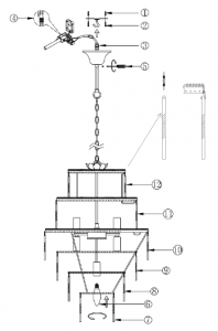
Never install your appliance on a wet, freshly painted or plastered surface. Ensure the house electricity supply is switched off at the fuse box. If removing an existing fitting, note down all wiring connections. Follow the diagram below for fixing detail. Check the fixings will not touch any existing wiring before drilling and attaching the light to the wall. Ensure you thread the wall wires through the black insulating tube fixed to the appliance.
- Ensure the house electricity supply is off at the fuse board.
- If removing an existing fitting, first note down all wiring connections.
- Remove mounting bracket from fitting by removing the retaining screws and washers, retain for later.
- Remove mounting hook from the ceiling cup. Using mounting bracket as a template, mark and then drill the fixing holes in the ceiling (ensure holes are drilled into a secure joist). Take care not to damage wiring.
- Attach mounting bracket to the mounting surface using suitable fixings. Do not attach fitting to mounting bracket at this stage. Make sure no wires are trapped in the process.
- This fitting is height adjustable at point of installation only. No attempt must be made to adjust the height once it has been attached to the ceiling. If adjustment is required at a later date the fitting must be isolated from the mains and removed from the ceiling first. Using two pairs of pliers carefully open the chain links and remove the required number of links. Close the links. Note: Cloth should be used between the jaws of the pliers to protect the decorative finish. Pull any excess cable through the ceiling cup.IMPORTANT ensure the chain is supporting the weight of the fitting and not the electrical cable.
- Attach the mounting hook bracket onto the ceiling using suitable screws. Make sure no wires are trapped in the process.
- Lever open the terminal block box cover with a screwdriver then feed supply cable through rubber sleeving. The weight of the fitting must be supported whilst making the electrical connections as follows:• Connect supply live (normally brown or red) to fitting live (marked “L”) on the terminal block.• Connect supply neutral (normally blue or black) to fitting neutral (marked “N”) on the terminal block.NO EARTH must be connected to any part of this fitting. If there are any earth wires present in the ceiling these must be terminated into a separate terminal block (not supplied) to ensure continuity of the earth circuit is maintained.NOTE: Ensure electrical connections are tight and no loose strands of wire are left out of the connector block. Ensure terminals and rubber sleeve are correctly seated then close connector block housing.
- Offer fitting over the mounting hook and secure fitting into position. Raise the ceiling cup to the top of the stem until it covers the ceiling hook mount. Tighten the retaining screw located on the bottom of the ceiling cup to retain in place hiding the ceiling connection. Take care not to trap wires in the process.
- Fit the bulbs, type and wattage as displayed on the fitting. The stated wattage must not be exceeded.
- Carefully remove the crystal droppers from their protective packaging and attach one by one. At the tips of each dropper is a soft metal, decorative clip, pass the end of the clip through the top hole on the frame and fold the edge of the clip over to fix the dropper in place. Once installation is complete, the house electricity may be restored at the fuse box.
Care instructions
Wipe clean with a clean dry cloth, when product is switched off and has cooled down.
Recommended bulb
9 x 28W E14 (SES) eco halogen GLS bulbOr9 x 8W energy saving spiral bulb
Specifications
Max. Power: 40WVoltage: 230V, 50Hz
Read More About This Manual & Download PDF:
References
[xyz-ips snippet=”download-snippet”]