
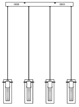
Johan LewisObelisk Led Bar PendantUser Manual
Thank you for purchasing this Obelisk LED bar pendant. Please read the instructions carefully before use to ensure safe and satisfactory operation of this product.
Warnings!
- For your safety, this product must be installed in accordance with local Building Regulations. If in any doubt, or where required by the law, consult a competent person who is registered with an electrical self-certification scheme. Further information is available online or phone your Local Authority.
- To prevent electric shock, switch off the mains supply before installing or maintaining this product. Ensure other persons cannot restore the electricity supply without your knowledge.
- Always use the correct bulb type with the correct wattage as indicated in the specification table. Never exceed the Max. power rating. When changing a bulb always switch off at the mains first and allow the bulb to cool down before handling. Dispose of used bulbs carefully. The bulb and surrounding parts can become extremely hot during use.
- This product is Class II =
 and should be fitted to a lighting Supply protected by a 5 amp fuse or equivalent circuit breaker.
 - The light source of this luminaire is not replaceable; when the light source reaches the end of its end of life the whole luminaire shall be replaced.
- For indoor use only.
Assembly
- Never install your appliance on a wet, freshly painted or plastered surface.
- Ensure the house electricity supply is switched off at the fuse box.
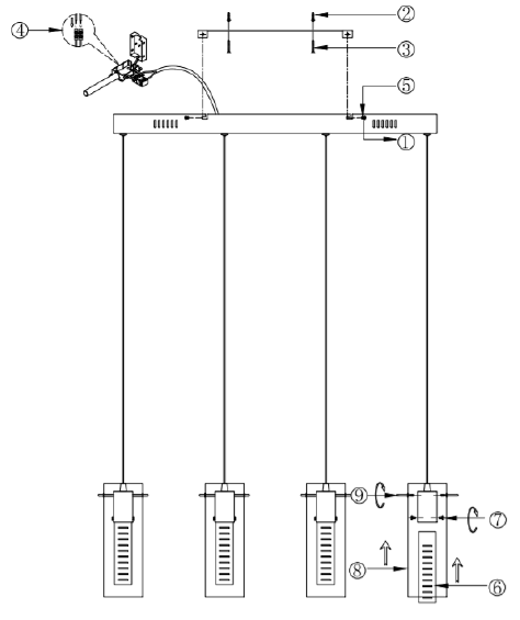
- If removing an existing fitting, note down all wiring connections.Follow the diagram below for fixing detail.
- Check the fixings will not touch any existing wiring before drilling and attaching the light to the wall.Ensure you thread the wall wires through the black insulating tube fixed to the appliance.
- Ensure the house electricity supply is off at the fuse board.
- If removing an existing fitting, first note down all wiring connections.
- Remove mounting bracket from fitting by removing the retaining screws and washers, retain for later.
- Using the mounting bracket as a template, mark and then drill the fixing holes in the ceiling (ensure holes are drilled into a secure joist). Take care not to damage wiring.
- Attach mounting bracket to the mounting surface using suitable fixings. Do not attach fitting to mounting bracket at this stage. Make sure no wires are trapped in the process.
- Height Adjustment: This fitting is height adjustable at point of installation only. To adjust the length of cable, pull the metal support wire through into the ceiling cup until the desired height is achieved. If you wish to lengthen the wire again simply push the small tube that the wire passes through in on itself (it is spring loaded) and gently pull the wire back through to the desired length, as soon as the tube is released it will automatically lock in position again. With the support wire length achieved pull the supply cable through into the ceiling cup until the desired length is achieved. Ensure that the supply cable is left slack so it is the metal support wire taking all of the strain of the weight once installed and not the supply cable.
- The stabilizer tube at the centre body for the supporting wire should be screwed in and secured now that the height is adjusted.
- Lever open the terminal block box cover with a screwdriver then feed supply cable through rubber sleeving. The weight of the fitting must be supported whilst making the electrical connections as follows:⇒ Connect supply live (normally brown or red) to fitting live (marked “L”) on the terminal block.⇒ Connect supply neutral (normally blue or black) to fitting neutral (marked “N”) on the terminal block.NO EARTH must be connected to any part of this fitting. If there are any earth wires present in the ceiling these must be terminated into a separate terminal block (not supplied) to ensure continuity of the earth circuit is maintained.NOTE: Ensure electrical connections are tight and no loose strands of wire are left out of the connector block. Ensure terminals and rubber sleeve are correctly seated then close connector block housing.
- Excess cable must be carefully located inside ceiling cup or within the ceiling void. Carefully offer fitting over mounting bracket then secure in place with the screws and washers removed earlier.
- IMPORTANT: Do not construct the shade assembly until the fitting has been installed onto the ceiling to reduce the risk of damage to the shades.To fit the shades: Place the decorative rectangular glass block shade inside the LED lamp holder housing. Align the holes in the shade with the holes in the housing directly opposite and screw into place using the screws provided to secure in place. Take care not to cross-thread or over tighten as this may cause damage to the glass or the fitting. Pass the outer glass shade covers over the top of the lamp holder and inner shade section. Align the holes in the outer shade with the adjacent screw holes located at the top of the lamp holder section. Insert the threaded metal support rods through the hole in the outer glass and into the lamp holder. Screw rods into place to suspend the outer glass. Attach the rods on all four sides of the shade. Note: The outer glass needs to be supported on at least two sides before the glass can hang unsupported from the fitting. Take great care during assembly not to allow the shades to collide together as this will cause damage to the fitting.
Once installation is complete, the house electricity may be restored at the fuse box.
Care instructions
Wipe clean with a clean dry cloth, when product is switched off and has cooled down.
Recommended bulb
- 4 x 4.5W LED not replaceable
Specifications
- Max. Power: 18W
- Voltage: 230V, 50Hz
Please retain these instructions for future reference.
John Lewis Partnership171 Victoria StreetLondon SW1E 5NNjohnlewis.comMade in China
References
[xyz-ips snippet=”download-snippet”]