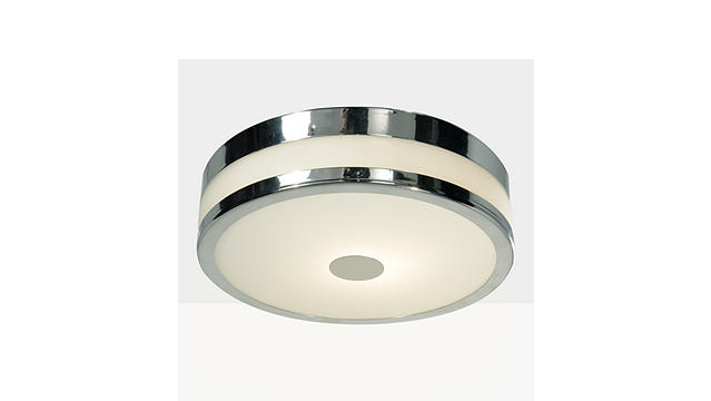
 SHIKO IP44 BATHROOM CEILING LIGHTIL1746Thank you for buying this Shiko bathroom ceiling light.Please read the instructions and warnings carefully before use to ensure safe and satisfactoryoperation of this product.
This product is Class I and must be earthed.
Warnings
- It is recommended that this fitting is installed by a qualified electrician.
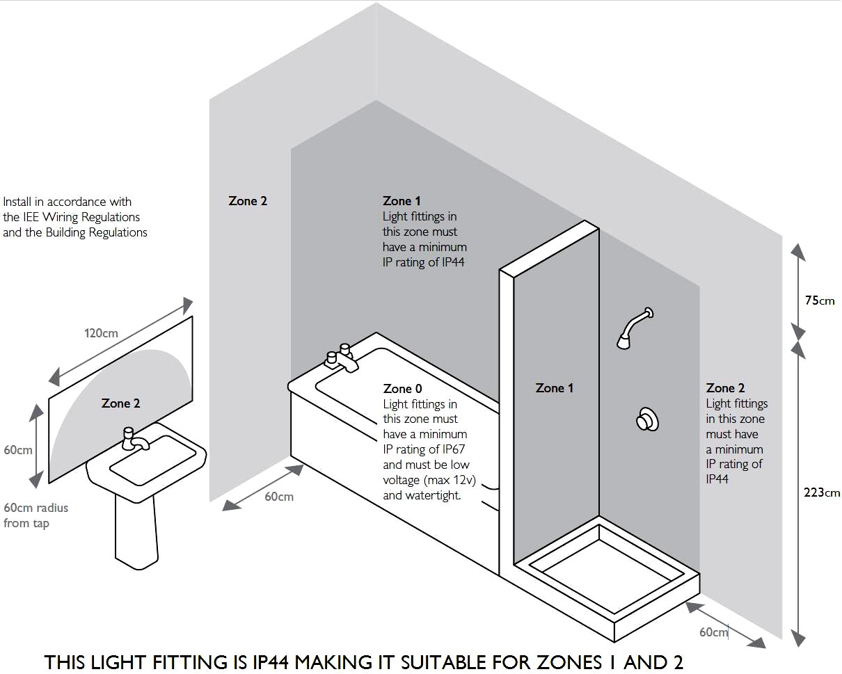
- This fitting should be fitted in accordance with IEE Wiring Regulations and the Building Regulations.
- To prevent electrocution switch off at the mains supply before installing or maintaining this fitting. Ensure other persons cannot restore the electricity supply without your knowledge.
- If you are in doubt please consult a qualified electrician.
- To avoid damage to concealed wiring during installation, establish the direction of the supply cable before drilling fixing holes.
- This fitting should be fitted to a lighting supply with a protected 5 amp fuse or equivalent circuit breaker.
 NOT suitable for mounting on normally flammable surfaces.
 - This fitting is rated IP44 making it suitable for use in Zones 1 & 2 of a bathroom when fitted in accordance with IEE wiring regulations (see diagram overleaf). Fitting must be connected to a supply protected by a 30mA RCD in Zones.
- Always be sure to use the correct type and wattage of bulbs as indicated on the fitting. Never exceed the wattage stated.
- When changing the bulb, always switch off at the mains and allow the old bulb to cool down before handling. Dispose of used bulbs carefully.
Instructions for use
- Ensure the house electricity supply is off at the fuse board.
- If you are fitting this unit in place of the existing light, you may find that there are more than 3 sets of cables connected within the rose. Before removing the existing fitting, carefully note the position of each set of cables. If there are permanently live loop-in cables that are not connected to the light these must be terminated in a separate terminal block not connected to the fitting.
- Using the fitting as a template, mark and then drill the fixing holes in the ceiling (ensure that the holes are drilled into a joist or solid object and not just the plaster).
- Make a suitable hole in the terminal block orange boot for the incoming supply cable and feed the supply cable through the hole.
- The weight of the fitting must be supported whilst you make the electrical connections. Slide one-half of each side of the rubber connector cover over each end of the incoming and outgoing wires. (See diagram on the opposite side for correct use of rubber connectors)Connect the supply live (normally brown or red) to terminal block marked ‘L’ or brown wire on fitting.Connect the supply neutral (normally blue or black) to terminal block ‘N’ or blue on fitting.Connect the supply earth (normally unsheathed or green/yellow) to the terminal block marked ‘‘ on fitting.Ensure electrical connections are tight and no loose strands of wire are left out of the connector block. Slide the rubber boots over the connector block to provide a watertight seal.
- Push the covered connector block inside the ceiling void and fix the ceiling plate to the ceiling using suitable screws.Ensure that the screws are fixed firmly into the ceiling joist and not just the plaster. The heads of the screws must be sealed with the small rubber washers included in the screw pack to prevent water ingress into the fitting. Take care not to trap or damage wiring
- Secure fitting into position with suitable screws.
- Fit the bulb: Type and wattage as indicated on the fitting. The wattage indicated must not be exceeded.
- To fit glass: First, ensure the rubber seal is positioned correctly on fitting. Offer the glass up to the fitting and twist clockwise until securely located.
- Switch on the electricity supply at the fuse board.
Please retain this information leaflet for future referenceGENERAL INFORMATIONThis fitting is designed for internal use onlyDo not use polish or an abrasive cleaner – just a soft dry cloth.
John Lewis Partnership 171 Victoria Street London SW1E 5NNwww.johnlewis.comIssue 2 05/09
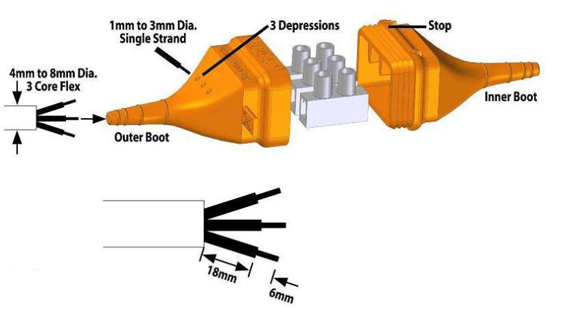
1P44 CONNECTOR BLOCK
The rubber boots on the connector block will provide a watertight seal to IP44 if connected as below.
- Separate the two halves of the boot by cutting the spur connecting them with scissors or a knife.
- Cut the ends off the rubber boots with sharp scissors or a knife to reveal a suitable size hole depending on the cable being used. The boot must be a tight fit around the insulation of the cable to ensure a watertight seal. It is therefore important not to cut the boots back too far. If you should cut back the boot too far the wire entry can be sealed with silicone mastic after step 8 below.
- If single strands of cable are being used these can be pushed through the top sidewall of the boot through the three depressions. (Shown below).
- Slide each boot backward over each end of the cables.
- Cut back the insulation on the wires as shown.
- Make connections in the connector block ensuring they are tight and no loose strands are left out of the connector block.
- Slide both boots back along the cable towards the connector block.
- Push the two halves of the boots together so the arrows on the top of the boot are in line. Fully engage the ribs in order to create a good watertight seal. The halves are fully engaged when the front edge of the outer boot is hard up against the stop on the inner boot.
- Take care to ensure the two halves of the boot are not pulled apart when the fitting is finally fitted.
John Lewis Partnership 171 Victoria Street London SW1E 5NNwww.johnlewis.comIssue 2 05/09
[xyz-ips snippet=”download-snippet”]