MP Series - Standard PSC Modular Multi-Position
Air Handlers User Manual

SECTION I: GENERAL
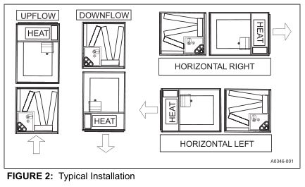
The MP modular air handler series provides the flexibility for installation in any position. This unit may be used for upflow, downflow, horizontal right, or horizontal left applications.
These units may be located in a closet, utility room, attic, crawl space, or basement. These versatile models may be used for cooling or heat pump operation with or without electric heat or indoor coil.
Top or side power and control wiring, color coded leads for control wiring, and electric heaters all combine to make the installation easy and minimize installation cost.
Electric heat kits are available as field installed accessories. Single phase kits are available from 2.5 kW to 20 kW.
SECTION II: SAFETY
![]()
This is a safety alert symbol. When you see this symbol on labels or in manuals, be alert to the potential for personal injury.
Understand and pay particular attention to the signal words DANGER, WARNING, or CAUTION.
DANGER indicates an imminently hazardous situation, which, if not avoided, will result in death or serious injury.
WARNING indicates a potentially hazardous situation, which, if not avoided, could result in death or serious injury.
CAUTION indicates a potentially hazardous situation, which, if not avoided may result in minor or moderate injury. It is also used to alert against unsafe practices and hazards involving only property damage.

FIRE OR ELECTRICAL HAZARDFailure to follow the safety warnings exactly could result in serious injury, death or property damage. A fire or electrical hazard may result causing property damage, personal injury or loss of life.
The air handler area must not be used as a broom closet or for any other storage purposes, as a fire hazard may be created. Never store items such as the following on, near or in contact with the furnace.
- Spray or aerosol cans, rags, brooms, dust mops, vacuum cleaners or other cleaning tools.
- Soap powders, bleaches, waxes or other Cleaning compounds; plastic items or containers; gasoline, kerosene, cigarette lighter fluid, dry cleaning fluids or other volatile fluid.
- Paint thinners and other painting compounds.
- Paper bags, boxes or other paper productsNever operate the air handler with the blower door removed. To do so could result in serious personal injury and/or equipment damage.
![]()
Improper installation, adjustment, alteration, or maintenance may create a condition where the operation of the product could cause personal injury or property damage. Refer to this manual for assistance, or for additional information, consult a qualified contractor, installer, or service agency.
![]()
This product must be installed in strict compliance with the installation instructions and any applicable local, state, and national codes including, but not limited to building, electrical, and mechanical codes.
SAFETY REQUIREMENTS
- Failure to carefully read and follow all instructions in this manual can result in air handler malfunction, death, personal injury and/or property damage.
- This air handler should be installed in accordance with all national and local building/safety codes and requirements, local plumbing or wastewater codes, and other applicable codes.
- This air handler should be installed only in a location and position specified in the “Unit Installation” section of this Instruction Manual.
- The air handler is not to be used for temporary heating of buildings or structures under construction.
- Always install the air handler to operate within the air handler’s intended maximum outlet air temperature.
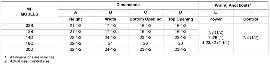
- The unit rating plate displays the air handler model number. The unit dimensions for the supply air plenum are provided in Figure 5 and Table 1 of this Instruction Manual. The plenum must be installed according to the instructions. The return air duct attachment is shown in Figure 1.
- Clearance from combustible material is provided under “Clearances” in the “Unit Installation” section.
- It is necessary to maintain clearances for servicing. Access must be allowed for electric heaters and blower.
- The unit rating plate and power supply must be verified to ensure that the electrical characteristics match.
- Air handler shall be installed so the electrical components are protected from water.
- Installing and servicing heating/cooling equipment can be hazardous due to the electrical components. Only trained and licensed personnel should install, repair, or service heating/cooling equipment. Unlicensed service personnel can perform basic maintenance functions such as cleaning and replacing the air filters. When working on heating/cooling equipment, the precautions in the manuals and on the labels attached to the unit and other safety precautions must be observed as applicable.
 These air handlers should be transported & handled in an upright, upflow position. Failure to do so may result in unit damage and personal injury. Configuration conversions should be done at site of installation.
 - These instructions cover minimum requirements and conform to existing national standards and safety codes. In some instances these instructions exceed certain local codes and ordinances, especially those who have not kept up with changing residential and non-HUD modular home construction practices. These instructions are required as a minimum for a safe installation.

INSPECTIONAs soon as a unit is received, it should be inspected for possible damage during transit. If damage is evident, the extent of the damage should be noted on the carrier’s freight bill. A separate request for inspection by the carrier’s agent should be made in writing. Also, before installation the unit should be checked for screws or bolts, which may have loosened in transit. There are no shipping or spacer brackets which need to be removed.
It should be verified that the appropriate coil and accessories (such as heater kit and thermostatic expansion valve kit) are available as required. Installation of these accessories or field conversion of the unit should be accomplished before setting the unit in place or connecting any wiring, duct work or piping.
SECTION III: UNIT INSTALLATION
UNIT SIZING
- The size of the unit should be based on an acceptable heat loss or gain calculation for the structure. The ACCA – Manual J or other approved methods may be used. Reference Figure 5 and Table 1.
- Only connect the air handler to a duct system which has an external static pressure within the allowable range.
- Airflow must be within the minimum and maximum limits approved for electric heat, indoor coils and outdoor units.
- When an air handler is installed so that supply ducts carry air circulated by the air handler to areas outside the space containing the air handler, the return air shall also be handled by duct(s) sealed to the air handler casing and terminating in the space to be cooled/heated.
- Refer to the unit rating plate for the air handler model number, and then see the dimensions page of this instruction for supply air plenum dimensions. The plenum must be installed according to the instructions.
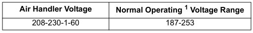
- The installer must check available supply power and verify that it is within the normal operating voltage range for the unit. The acceptable voltage range for these units is as follows:
- Rated in accordance with ARI Standard 110, utilization range “A”.

CLEARANCESClearances must be taken into consideration, and provided for as follows:
- Maintenance and servicing access – minimum 36” from front of unit recommended for blower motor / coil replacement.
- The duct work connected to this unit is designed for zero clearance to combustible materials.
- A combustible floor base accessory is available for downflow applications of this unit, if required by local code.
LOCATIONLocation is usually predetermined. Check with owner’s or dealer’s installation plans. If location has not been decided, consider the following in choosing a suitable location:
- Select a location with adequate structural support, space for service access, and clearance for air return and supply duct connections.
- Using hanging brackets to wall mount this single piece air handler unit is not recommended.
- Normal operating sound levels may be objectionable if the air handler is placed directly over some rooms such as bedrooms, study, etc.
- If using the air handler unit with an indoor coil, select a location that will permit installation of condensate line to open drain or outdoors allowing condensate to drain away from structure.NOTICEThe primary and secondary drain line must be trapped to allow proper drainage of condensate water. The secondary drain line should be piped to a location that will give the occupant a visual warning that the primary drain is clogged. If the secondary drain line is not used, it must be capped.
- When an indoor coil is installed in an attic or above a finished ceiling, an auxiliary drain pan should be provided under the air handler as is specified by most local building codes.
- Proper electrical supply must be available.
- If unit is located in an area of high humidity (i.e. an unconditioned garage or attic), nuisance sweating of casing may occur. On these installations, unit duct connections and other openings should be properly sealed, and a wrap of 2” fiberglass insulation with vinyl vapor barrier should be used.
AIR HANDLER CONFIGURATIONThese air handler units are supplied ready to be installed in an upflow, downflow, horizontal right or horizontal left position. Refer to Figure 2. The unit requires no conversion procedures.
AIR HANDLER AND COIL UPFLOW, DOWNFLOW, AND HORIZONTAL POSTIONS
- Apply neoprene gasket to the return air end of air handler.
- Attach three tie plates to external sides and back of air handler casing using screws. Refer to Figure 3.
- Position blower casing over appropriate coil opening (depending on configuration). Refer to Figure 2.
- Attach the three tie plates to coil casing using screws. Refer to Figure 3.
- Remove coil access panel.
- Slide the coil out of the coil cabinet, and set coil to the side.
- Locate 2” wide foam gasket.
- Apply foam gasket over the air handler and coil mating seams on the interior of both unit sides and back. Refer to Figure 4.
- Slide the coil into the housing, and install the coil access panel.
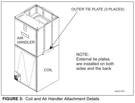
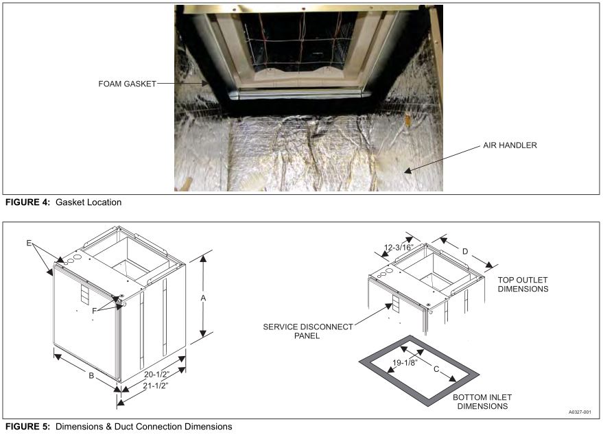
TABLE 1: Dimensions¹
SECTION IV: DUCT WORK AND CONNECTIONS
![]()
Use only 1/2” screws to connect duct work to bottom of unit.
Air supply and return may be handled in one of several ways best suited to the installation. Upflow, horizontal or downflow applications may be used.
The vast majority of problems encountered with heating and cooling systems can be linked to improperly designed or installed duct systems. It is therefore highly important to the success of an installation that the duct system be properly designed and installed.
When installing a central air return grille in or near the living space, it is advisable to design the duct work so that the grille is not in direct line with the opening in the unit. One or two elbows and acoustical duct liner assures a quieter system. Operation where return air duct is short or where sound may be a problem, acoustical duct liner should be used inside the duct. If electric heat is used, non-flammable material must be used.
Use flexible duct connectors to minimize the transmission of vibration/noise into the conditioned space. Never fasten duct work directly to the structure.
Do not bring in return air from a location which could introduce hazardous substances into the airflow.Use 1/2” screws to connect duct work to cabinet. If pilot holes are drilled, drill only through field duct and unit flange.
![]()
This unit is not designed for non-ducted (freeblow) applications. Do not operate without duct work attached to unit.Equipment should never be operated without filters.
Insulation of duct work is a must where it runs through an unheated space during the heating season or through an uncooled space during the cooling season. The use of a vapor barrier is recommended to prevent absorption of moisture from the surrounding air into the insulation.
The supply air duct should be properly sized by use of a transition to match unit opening. All ducts should be suspended using flexible hangers and never fastened directly to the structure. Duct work should be fabricated and installed in accordance with local and/or national codes. This includes the standards of the National Fire Protection Association for Installation of Air-Conditioning and Ventilating Systems, NFPA No. 90B. Duct systems should be designed in accordance with the Air Conditioning Contractors of America (ACCA) – Manual D.
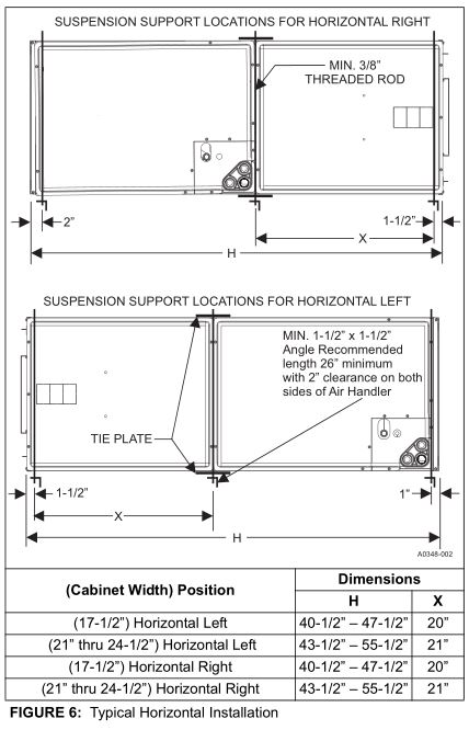
HORIZONTAL SUSPENSIONFor suspension of these units in horizontal applications, it is recommended to use angle steel support brackets with threaded rods, supporting the units from the bottom, at the locations shown in Figure 6.
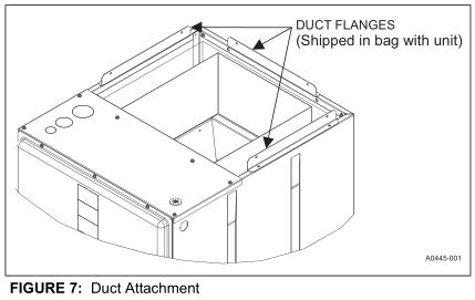
DUCT FLANGESThree duct flanges are provided to assist in positioning and attaching duct work to the air handler. These flanges are included in the unit parts bag. With the screws from the parts bag, install one of the duct flanges. Duct flanges have holes on both legs with one leg longer than the other. The longer leg can be used to mate against the air handler so that different thicknesses of duct board can be made flush with the outer surface of the air handler. Repeat the procedure for the other two flanges. Refer to Figure 7. If the flanges are not used, they may be discarded.
![]()
UNIT CONNECTIONSThere are several ways to handle the supply and return air duct connections. The location and sizing of the connections depends on the situation and the method best suited to the installation. Upflow, horizontal or downflow applications may be used. The supply air duct should be properly sized by use of a transition to match unit opening. Refer to Table 1 for air handler unit inlet and outlet dimensions.
![]()
Use 1/2” screws to connect duct work to unit. Longer screws will pierce the drain pan and cause leakage. If pilot holes are drilled, drill only though field duct and unit bottom duct flange.
Duct work that is not designed to match the supply air opening can cause turbulence inside the plenum. This turbulence can change the air flow patterns across the electric heater limit switches. If the factory suggested transition cannot be fabricated, it is recommended that a block off plate (approximately 8″ high and running the full width of the plenum) be attached to the supply opening. Refer to Figure 8 as a visual aid. The use of this block off plate will enable better air circulation across the limit switches.
AIR FILTERSReturn air filters are required and must be field supplied. Filtration must be accomplished external to the unit.
![]()
Equipment should never be operated without filters.
SECTION V: ELECTRIC HEATER INSTALLATION
If the air handler requires electric heat, install the electric heat kit according to the installation instructions included with the kit. After installing the kit, mark the air handler nameplate to designate the heater kit that was installed. If no heater is installed, mark the name plate appropriately to indicate that no heat kit is installed.
Use only 6HK Revision C or later heater kits, as listed on air handler name plate and in these instructions. Use data from Tables 4 through 9 for information on required minimum motor speed tap to be used for heating operation, maximum over-current protection device required as listed for combination of air handler and heater kit.
SECTION VI: LINE POWER CONNECTIONS
Power may be brought into the unit through the supply air end of the unit (top left when unit is vertical) or the left side panel. Use the hole appropriate to the unit’s orientation in each installation to bring conduit from the disconnect. The power lead conduit should be terminated at the electrical control box. Refer to Tables 3, 8 and 9 to determine proper wire sizing. Refer to the latest edition of the National Electric Code or in Canada the Canadian electrical Code and local codes to determine correct wire sizing. To minimize air leakage, seal the wiring entry point at the outside of the unit. All electrical connections to air handlers must be made with copper conductors. Direct connection of aluminum wiring to air handlers is not approved.
If aluminum conductors are present, all applicable local and national codes must be followed when converting from aluminum to copper conductors prior to connection to the air handler.The chosen conductor and connections all must meet or exceed the amperage rating of the overcurrent protector (service disconnect or fuse) in the circuit.Additionally, existing aluminum wire within the structure must be sized correctly for the application according to National Electric Code and local codes. Caution must be used when sizing aluminum rather than copper conductors, as aluminum conductors are rated for less current than copper conductors of the same size.

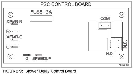
SECTION VII: LOW VOLTAGE CONTROL CONNECTIONS
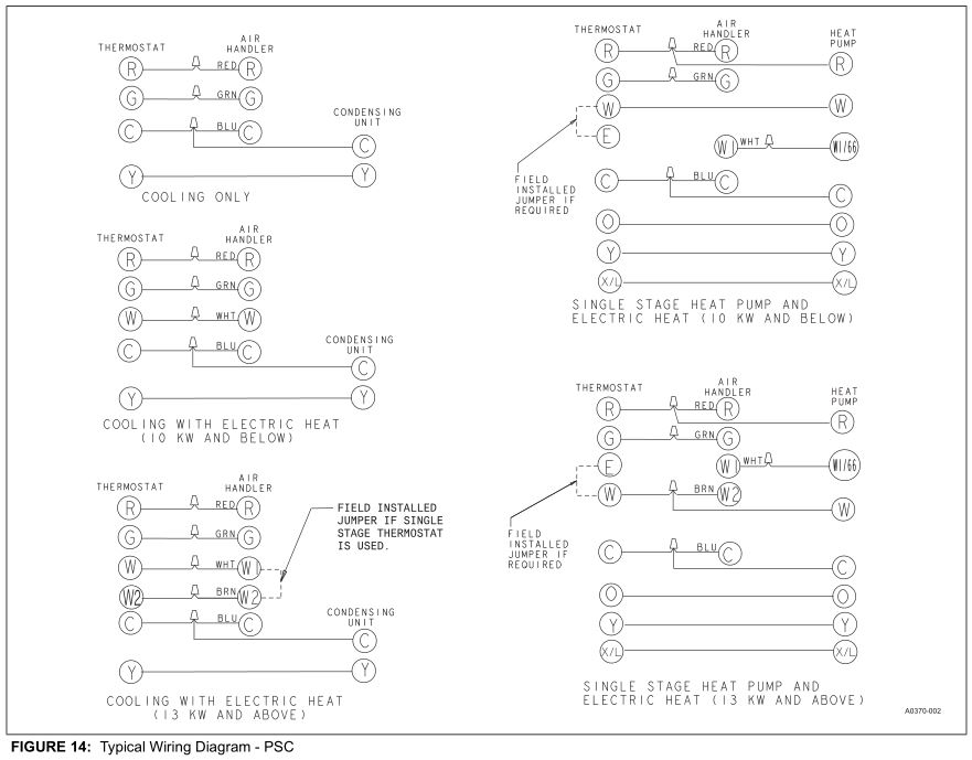
The 24 volt power supply is provided by an internally wired low voltage transformer which is standard on all models. if the unit is connected to a 208 volt power supply, the low voltage transformer must be rewired to the 208 volt tap. See the unit wiring diagram.Field supplied low voltage wiring can exit the unit through the top right (when unit is vertical upflow) or the right side panel. Refer to Figure 5.Remove desired knockout and pierce foil faced insulation to allow wiring to pass through. Use as small of a hole as possible to minimize air leakage. Install a 7/8” plastic bushing in the selected hole and keep low voltage wiring as short as possible inside the control box.To further minimize air leakage, seal the wiring entry point at the outside of the unit.The field wiring is to be connected at the pigtails supplied with the air handler. Refer to Figures 13 and 14 for system wiring.
NOTICEAll wiring must comply with local and national electrical code requirements. Read and heed all unit caution labels.
NOTICEIt is possible to vary the amount of electric heat turned on during the defrost cycle of a heat pump. Standard wiring will only bring on the first stage of electric heat during defrost. See Table 7 for additional information on heat during defrost cycle.
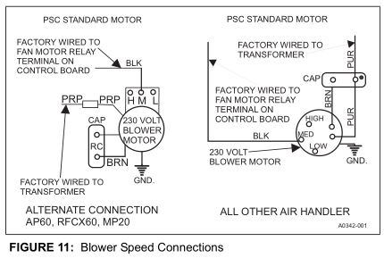
SECTION VIII: BLOWER SPEED CONNECTIONS
Adjust blower motor speed to provide airflow within the minimum and maximum limits approved for indoor coil, electric heat and outdoor unit. Speed tap adjustments are made at the motor terminal block. Airflow data is shown in Table 10.Connect motor wires to motor speed tap receptacle for speed desired. See unit wiring label for motor wiring details. Blower Speed Connections
SECTION IX: UNIT DATA
TABLE 2: Physical and Electrical Data – Cooling Only
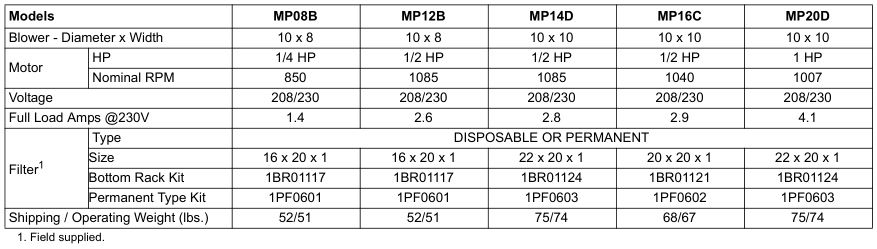
TABLE 3: Electrical Data – Cooling Only

TABLE 4: Electrical Heat: – Minimum Fan Speed
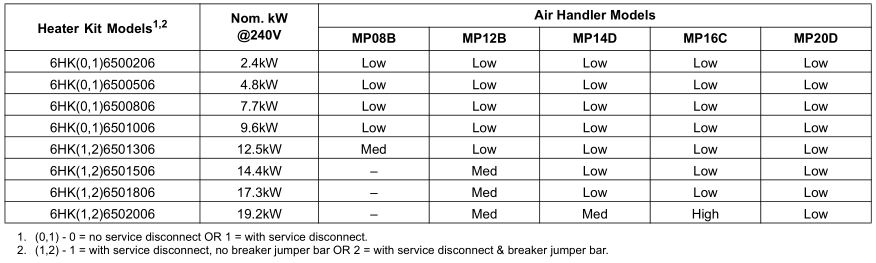
TABLE 5: KW & MBH Conversions – For Total Power Input Requirement
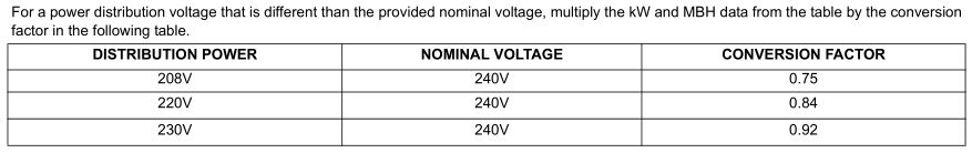
TABLE 6: Electric Heat Performance Data: 208/230-1-60
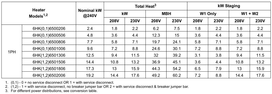
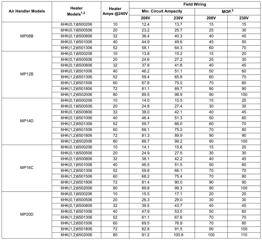
TABLE 7: Electrical Data For Single Source Power Supply: 208/230-1-60
- (0,1) – maybe 0 (no service disconnect) or 1 (with service disconnect).
- (1,2) maybe 1 (with service disconnect, no breaker jumper bar) or 2 (with service disconnect & breaker jumper bar).
- MOP = Maximum Overcurrent Protection device; must be HACR type circuit breaker or time delay fuse . Refer to the latest edition of the National Electric Code or in Canada the Canadian electrical Code and local codes to determine correct wire sizing.
TABLE 8: Electrical Data For Multi-source Power Supply: 208/230-1-60

- (0,1) – maybe 0 (no service disconnect) or 1 (with service disconnect).
- (1,2) maybe 1 (with service disconnect, no breaker jumper bar) or 2 (with service disconnect & breaker jumper bar).
- MOP = Maximum Overcurrent Protection device; must be HACR type circuit breaker or time delay fuse. The 1st Circuit includes the blower motor amps. Refer to the latest edition of the National Electric Code or in Canada the Canadian electrical Code and local codes to determine correct wire sizing.
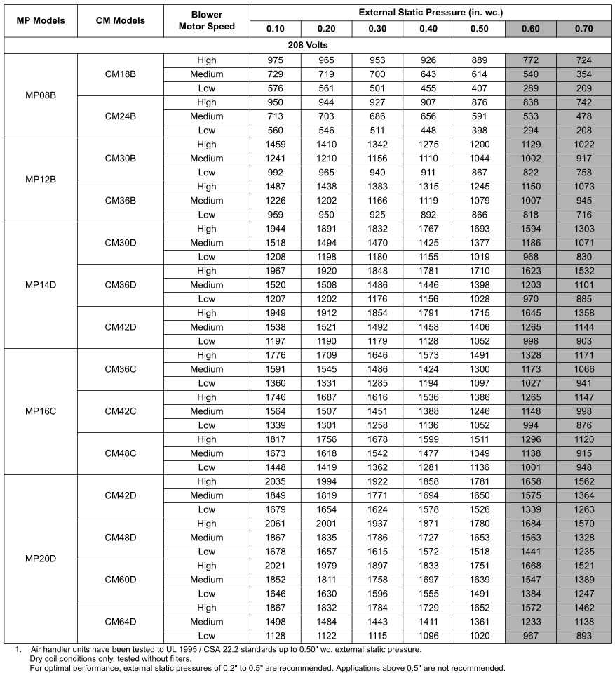
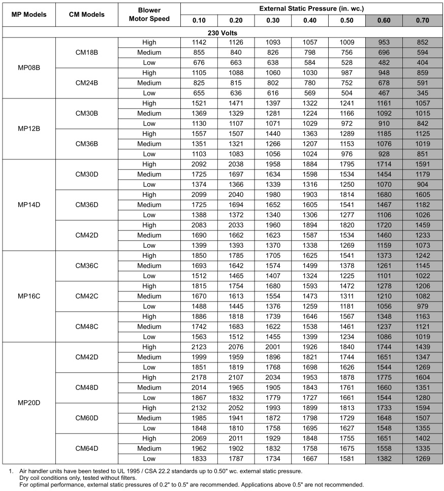
TABLE 9: Air Flow Data (CFM)¹
SECTION X: MAINTENANCE
Filters must be cleaned or replaced when they become dirty. Inspect at least once per month. The frequency of cleaning depends upon the hours of operation and the local atmospheric conditions. Clean filters keep unit efficiency high.
COIL CLEANINGIf the coil needs to be cleaned, it should be cleaned with water.
LUBRICATIONThe bearings of the blower motor are permanently lubricated.
CONDENSATE DRAINSDuring the cooling season check the condensate drain lines to be sure that condensate is flowing from the primary drain but not from the secondary drain. If condensate ever flows from the secondary drain the unit should be promptly shut off and the condensate pan and drains cleaned to insure a free flowing primary drain.
SECTION XI: AIR SYSTEM ADJUSTMENT
To check the Cubic Feet per Minute (CFM), measure external duct static using a manometer and static pressure tips. To prepare coil for static pressure drop measurements run the fan only to assure a dry coil.
NOTICERefer to Table 10 for coil Air Flow Data of Cubic Feet Per Minute (CFM). Run the fan on the highest speed to be used.
Drill 2 holes, one 12” away from the air handler in the supply air duct and on 12” away from the air handler in the return air duct (before any elbows in the duct work). Insert the pressure tips, and energize the blower motor. See Table 10 to determine the air flow, and make the necessary adjustments to keep the CFM within the airflow limitations of the coil.
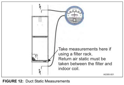
EXTERNAL DUCT STATICMeasure the supply air static pressure. Record this positive number. Measure the return air static pressure. Record this negative number. Treat the negative number as a positive, and add the two numbers together to determine the total external system static pressure. If a filter rack is installed on the return air end of the air handler or indoor coil section, make sure to measure the return air duct static between the filter and the indoor coil.
SECTION XII: WIRING DIAGRAM

SECTION XIII: TYPICAL THERMOSTAT CONNECTIONS
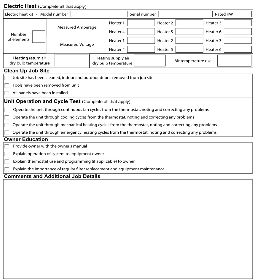
SECTION XIV: START UP SHEET

Subject to change without notice. Published in U.S.ACopyright © 2015 by Johnson Controls, Inc. All rights reserved.
1190828-UIM-G-0915Supersedes: 1190828-UIM-F-0915
York International Corp.5005 York DriveNorman, OK 73069
MP Series – Standard PSC Modular Multi-Position Air Handlers User Manual – MP Series – Standard PSC Modular Multi-Position Air Handlers User Manual –
[xyz-ips snippet=”download-snippet”]