
JOHNSON Self-Leveling Cross-Line Laser Instruction Manual
Kit Contents
|
Description for Model 40-6603 (Red) |
Qty |
|
Self-Leveling Cross-Line Laser |
1 |
|
“AA” Alkaline Batteries |
2 |
|
Description for Model 40-6601 (Green) & 40-6605 (Red) |
Qty |
|
Self-Leveling Cross-Line Laser |
1 |
|
Magnetic Bracket |
1 |
|
Tinted Glasses |
1 |
|
Magnetic Target |
1 |
|
“AA” Alkaline Batteries |
2 |
|
Hard-Shell Carrying Case |
1 |
|
Description for Model 40-6609 (Green) |
Qty. |
|
Self-Leveling Cross-Line Laser |
1 |
|
Magnetic Bracket |
1 |
|
“AA” Alkaline Batteries |
2 |
|
Soft-Sided Carrying Case |
1 |
Features and Functions
- Simultaneously projects two laser beams both horizontally (level) and vertically (plumb)
- Tilt mode can be used to plot lines at any angle
- Magnetically dampened compensator system stabilizes the pendulum quickly and accurately, and stays level even with nearby jobsite vibration.
- Status light alerts when the laser is beyond its leveling range
- Locking mechanism protects the pendulum during transportation
- 1/4″-20 tripod thread for use with most common tripods
Safety Instructions
Please read and understand all of the following instructions, prior to using this tool. Failure to do so, may void the warranty.
DANGER!Class II Laser ProductMax. Power Output: ≤ 1mWWavelength: 635nm (40-6603 & 40-6605)THIS TOOL EMITS LASER RADIATION.DO NOT STARE INTO BEAM. AVOID DIRECT EYE EXPOSURE.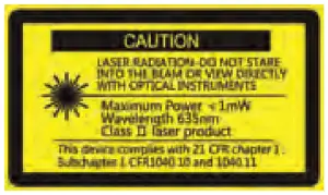
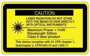
DANGER!Class II Laser ProductMax. Power Output: ≤ 1mWWavelength: 520nm (40-6601 & 40-6609)THIS TOOL EMITS LASER RADIATION.DO NOT STARE INTO BEAM.AVOID DIRECT EYE EXPOSURE.
ATTENTION
IMPORTANT
- Read all instructions prior to operating this laser tool. Do not remove any labels from tool.
- Do not stare directly at the laser beam.
- Do not project the laser beam directly into the eyes of others.
- Do not set up laser tool at eye level or operate the tool near a reflective surface as the laser beam could be projected into your eyes or into the eyes of others.
- Do not place the laser tool in a manner that may cause someone to unintentionally look into the laser beam. Serious eye injury may result.
- Do not operate the tool in explosive environments, i.e. in the presence of gases or flammable liquids.
- Keep the laser tool out of the reach of children and other untrained persons.
- Do not attempt to view the laser beam through optical tools such as telescopes as serious eye injury may result.
- Always turn the laser tool off when not in use or left unattended for a period of time.
- Remove the batteries when storing the tool for an extended time (more than 3 months) to avoid damage to the tool should the batteries deteriorate.
- Do not attempt to repair or disassemble the laser tool. If unqualified persons attempt to repair this tool, warranty will be void.
- Use only original Johnson® parts and accessories purchased from your Johnson® authorized dealer. Use of non-Johnson® parts and accessories will void warranty.
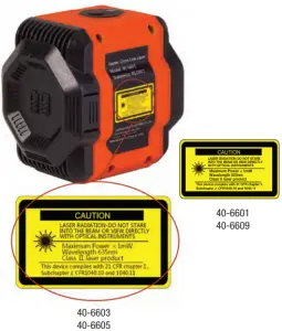
Location/Content of Warning Labels
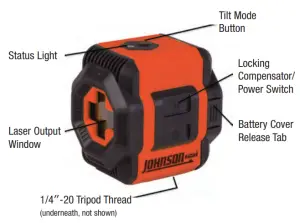
Location of Parts/Components
Operating Instructions
IMPORTANT: It is the responsibility of the user to ensure proper maintenance of the Self-Leveling Cross-Line Laser. Conduct periodic test measurements to ensure the tool is measuring accurately and consistently. This is most important if the tool has been exposed to extreme temperatures or moisture. Keep the Self-Leveling Cross-Line Laser optic lens clean and inspect for damage.
Battery Installation
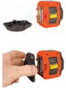
To install batteries in the Self-Leveling Cross-Line Laser:
- Remove the battery cover, which is located at the back of the tool, by pressing the battery cover release tabs found on the left and right sides of the tool and pulling the cover straight out from the tool housing.
- Insert 2 “AA” batteries into the battery compartment according to the polarity illustrated inside the battery compartment.
- Replace the battery cover. Press in the release tabs as you insert them into the tool housing.
Note
- Always check that the locking compensator/power switch is in the locked position before removing and replacing batteries.
- Use only alkaline batteries.
- Remove the batteries when storing the tool for an extended time (more than 3 months) to avoid damage to the tool should the batteries deteriorate.
Using the Product in Self-Leveling Mode
Slide the locking compensator up to the unlocked position to power on the unit. The status light will illuminate, and the unit will emit two laser beams.Slide the locking compensator down to the unlocked position to power off the unit.
Note: The tool must be within ±4° of level for the self-leveling feature to function properly. If the tool is beyond its 4° self-leveling range, the laser will not self-level, the laser will flash and the status light will turn red. Once the tool has been adjusted to within its 4° self-leveling range, the laser will self-level, the status light will turn green and the laser light will stop flashing and remain solid.
Using the Product in Tilt (Manual Level) Mode
The tool can be used to project laser beams at any angle desired, such as when projecting a line for stairs or a railing. This mode produces the best results when the tool is mounted on a tripod.
With the locking compensator down in the locked position, press the tilt mode button to power on the unit. The status light will illuminate in red to indicate that the tool is not self-leveling, and the unit will emit two laser beams. The lasers will be perpendicular to each other, but will not self level.
Press the tilt mode button to power off the unit.
Tips from the Pros
- Increasing the beams’ visibility – When working in bright conditions, such as when working near windows or outside walls, the visibility of the laser beams can be maximized by following these steps:
- Work towards the laser.
- Use a freestanding target (included with some models).
- Wear laser glasses (included with some models).
Note: Laser glasses enhance beam visibility but should never be used to stare into the beam or be used as safety glasses. Eye damage may result if these directions are not followed.
Care and Handling
- This laser is a precision tool that must be handled with care.
- Avoid exposing unit to shock vibrations and extreme temperatures.
- Remove the batteries when storing the unit for an extended time (more than 3 months) to avoid damage to the unit should the batteries deteriorate.
- Avoid getting the unit wet.
- Keep the laser unit dry and clean, especially the laser output window. Remove any moisture or dirt with a soft, dry cloth.
- Do not use harsh chemicals, strong detergents or cleaning solvents to clean the unit.
Checking Accuracy
IMPORTANT: It is the responsibility of the user to verify the calibration of the tool before each use.
Plumb Accuracy Check
Plumb accuracy can be checked in two ways. The easier, though less accurate method is to project the beam on a flat wall and use a plumb bob to check the plumb of the beam.
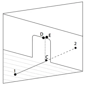
The more accurate method to check the plumb line accuracy is to follow these steps:
- Place the tool on the floor in a fairly dark room, approximately 10′ from a doorway.
- Project the plumb beam through the doorway.
- Mark the plumb beam’s closet point to the tool on the floor as Point 1.
- Mark a spot 20′ away as Point 2.

- Mark directly under the doorway as Point C.
- Mark a spot directly above Point C, but on the doorway, as point D.
- Move the tool to Point 2, and aim the plumb beam directly through Point 1 and Point C.
- Mark on the doorway Point E
- Measure the distance between Point D and Point E. If this distance is < 1/8″ for a 10′ high doorway, then the tool is properly calibrated.
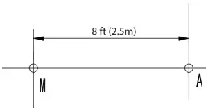
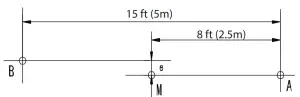
Horizontal Line Transverse Accuracy Check
Transverse accuracy refers to the accuracy of the horizontal laser beam projected along the wall and ensures the beam is level from left to right.
- Set the tool on a tripod and place approximately 15′ from a wall.
- Unlock and power the unit on.
- Face the laser line to the wall, and set the center as Point A.
- Make a mark on the wall for Point A.
- Make another mark on the wall 8′ from Point A and mark on the wall as Point M.
- Rotate the tool 90° and make a mark on the wall 15′ from Point A. Label this mark as Point B.
- Measure the distance ‘e’ from Point M to the laser line, as per the figure. If ‘e’ < 3/16″, then the tool is properly calibrated.
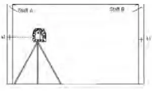
Horizontal Pitch Accuracy Check
Pitch accuracy refers to the accuracy of the laser between the tool and the wall and ensures that the horizontal beam is level between the tool and the wall.
- Set up two survey-staffs OR use two walls, both a minimum of 15′ from each other.
- Set the tool on a level tripod as close as possible to staff/wall A.
- Power on all laser lines and move the laser until the cross dot projects on the staff/wall A. Make a mark and label as A1.
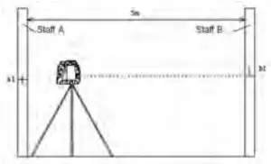
- Rotate the tool 180° and make the cross dot project on the staff/wall B. Make a mark and label as B1.
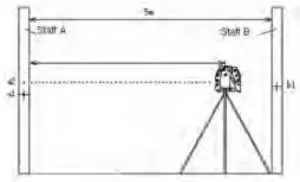
- Move the tripod as close as possible to wall B, and make the cross dot project on the staff/wall A. Make a mark and label as A2.
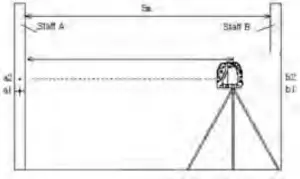
- Rotate the tool by 180° and move the cross dot to project on the staff/wall B. Make a mark and label as B2.
- Calculate the vertical distance (A1-A2) – (B1-B2) = e
- If e < 3/16″ at 15′, the tool is properly calibrated.
Application Examples
Cross line lasers are extremely versatile devices that have many useful applications designed to help you work more efficiently and effectively, including:
- Plumb layout of studs
- Level layout of chair rails, wainscoting, baseboards, etc.
- Installing photographs plumb or level
- Plumb layout of wallpaper, pinstriping, plumbing and electrical conduit, etc.
- As a level reference for setting the slope of drainage piping
- In tilt mode to layout railings, photographs and other wall art at any angle
- Setting tile or other flooring on walls and floors
- Installing partitions, windows or doorways
- Fixing cabinetry
- As a measuring reference for checking spacing or the angle of objects
Troubleshooting Guide
This section is designed to help you diagnose and troubleshoot common problems that prevent the tool from working properly.
| Symptom | Possible Cause | Solution |
| Will not turn on | Batteries missing or depleted
Polarity reversed |
Change the batteries
Check battery polarity |
| Turns off after a short time | Batteries depleted | Change the batteries |
| Laser light is dim | Batteries depleted | Change the batteries |
| Laser light is blinking | Laser is out of self leveling range | Position laser within 4° of level so that it can self-level |
| Laser will not self-level | Laser is out of self leveling range
Compensator is locked |
Position laser within 4° of level so that it can self-level
Unlock compensator to allow the pendulum to self-level; operating with the compensator locked is for tilt/manual level mode at unique angles |
Technical Specifications
- Laser Wavelength: 635 nm (40-6603 & 40-6605)
- Laser Wavelength: 520 nm (40-6601 & 40-6609)
- Laser Classification: II
- Maximum Power Output ≤1mW
- Self-Leveling Range: ±4°
- Laser Accuracy: ±3/16″/ 30′
- Measuring Range: 0′ – 50′
- Power Supply: 2 “AA” alkaline batteries (included)
- Battery Life*: 36 hours/20 hours (40-6603 & 40-6605)16 hours/9 hours (40-6601 & 40-6609)
- Operating Temperature Range: 32°F – 104°F
- Storage Temperature Range: 0°F – 120°F
- Dimensions: 3″ x 3″ x 2.37″
- Weight: 0.53 lbs
- Tripod Thread: 1/4″ – 20
- IP Rating: IP 50
Battery life reported with all beams enabled, as tested with lithium AA/Alkaline AA.
Product Warranty
Johnson Level & Tool offers a two year limited warranty on each of its products. You can obtain a copy of the limited warranty for a Johnson Level & Tool product by contacting Johnson Level & Tool’s Customer Service Department, as provided below, or by visiting our web site at www.johnsonlevel.com. The limited warranty for each product contains various limitations and exclusions.
Do not return this product to the store/retailer or place of purchase. Non-warranty repairs and course calibration must be done by an authorized Johnson® service center or Johnson Level & Tool’s limited warranty, if applicable, will be void and there will be NO WARRANTY. Contact one of our service centers for all non-warranty repairs. A list of service centers can be found on our web site at www.johnsonlevel.com or by calling our Customer Service Department. Contact our Customer Service Department for Return Material Authorization (RMA) for warranty repairs (manufacturing defects only). Proof of purchase is required.
NOTE: The user is responsible for the proper use and care of the product. It is the responsibility of the user to verify the calibration of the tool before each use.
For further assistance, or if you experience problems with this product that are not addressed in this instruction manual, please contact our Customer Service Dept.
In the U.S., contact Johnson Level & Tool’s Customer Service Department at [email protected] or 888-953-8357.
In Canada, contact Johnson Level & Tool’s Customer Service Department at 800-346-6682.
Warranty Registration
Please register within 30 days of purchase. Registering ensures we have your information on file for warranty service even if you lose your receipt, and lets us contact you if there is ever a product recall. We will never sell your information and only send you marketing information if you opt-in.
To register, go to www.johnsonlevel.com/register.
 report this ad
References
[xyz-ips snippet=”download-snippet”]