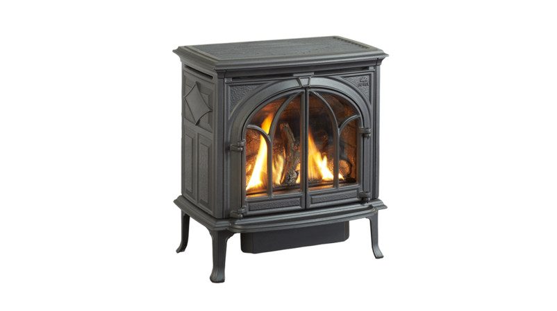

 Jøtul GF 400 DV MVSebagoDirect Vent Gas StovePilot-on-Demand Ignition
Installation and Operation Instructions
Certified to ANSI Z21.88-2016 • CSA 2.33-2016,and CAN/CGA 2.17-M17.Une version canadienne-française de ce manuel estdisponible sur www.jotul.ca.
INSTALLER: Leave this manual with the appliance.CONSUMER: Retain this manual for future reference.
WARNING: If the information in these instructions is not followed exactly, a fire or explosion may result causing property damage, personal injury or loss of life.– Do not store or use gasoline or other flammable vapors and liquids in the vicinity of this or any other appliance.– WHAT TO DO IF YOU SMELL GAS
- Do not try to light any appliance.
- Do not touch any electrical switch; do not use any phone in your building.
- Immediately call your gas supplier from a neighbor’s phone. Follow the gas supplier’s instructions.
- If you cannot reach your gas supplier, call the fire department.
– Installation and service must be performed by a qualified installer, service agency, or gas supplier.– In the Commonwealth of Massachusetts, a carbon monoxide (CO) detector shall be installed in the same room as the appliance.
This appliance may be installed in an aftermarket, permanently located, manufactured home, or mobile home, where not prohibited by local codes. This appliance is only for use with the types of gas indicated on the rating plate. A conversion kit is supplied with the appliance.
| THIS OWNER’S MANUAL PROVIDES INFORMATION TO ENSURE SAFE INSTALLATION AND EFFICIENT, DEPENDABLE OPERATION OF YOUR FIREPLACE INSERT. PLEASE READ THESE INSTRUCTIONS IN THEIR ENTIRETY AND MAKE THEM AVAILABLE TO ANYONE USING OR SERVICING THIS GAS INSERT.
DO NOT ATTEMPT TO ALTER OR MODIFY THE CONSTRUCTION OF THIS APPLIANCE OR ITS COMPONENTS. ANY MODIFICATION OR ALTERATION WILL VOID THE WARRANTY, CERTIFICATION, AND LISTING OF THIS APPLIANCE. THIS HEATER MUST BE INSTALLED AND MAINTAINED BY A QUALIFIED SERVICE AGENCY. |
Suggested Tools for Installation and Service
|
|
|
|
PLEASE NOTE:It is normal for smoke and odor to occur during the initial stages of operation, depending upon temperatures generated over time. This “curing” condition can be alleviated by promoting fresh air circulation within the immediate vicinity of the appliance.
Installation Requirements for the Commonwealth of Massachusetts THIS PRODUCT MUST BE INSTALLED BY A LICENSED MASTER OR JOURNEYMAN PLUMBER OR GAS FITTER WHEN INSTALLED IN THE COMMONWEALTH OF MASSACHUSETTS.
- If there is not one already present, on each floor level where there are bedroom(s), a carbon monoxide detector and alarm shall be placed in the living area outside the bedroom(s). The carbon monoxide detector shall comply with NFPA 720 (2005 Edition).
- A carbon monoxide detector shall:a) Be located in the room that houses the appliance or equipment;b) Be either hard-wired or battery-powered or both; andc) Shall comply with NFPA 720 (2002 Edition).
- A Product-approved vent terminal must be used, and if applicable, a Product-approved air intake must be used. Installation shall be in strict compliance with the manufacturer’s instructions. A copy of the installation instructions must remain with the appliance or equipment at the completion of the installation.
 |
We recommend that our gas products be installed and serviced by professionals who are certified in the U.S. by the National Fireplace Institute® (NFI) as NFI Gas Specialists. |
|
Jøtul GF 400 DV MV Sebago Manufactured and Distributed by:Jøtul ASFredrikstad, NorwayJøtul North America55 Hutcherson Dr.Gorham, Maine 04038-2634 Test Standards This appliance complies with National Safety standards and is tested and listed by Intertek Testing Services of Middleton, Wisconsin to ANSI Z21.88-2016,• CSA 2.33-2016 and CAN/CGA 2.17-M17. DO NOT ATTEMPT TO ALTER OR MODIFY THE CONSTRUCTION OF THE APPLIANCE OR ITS COMPONENTS. ANY MODIFICATION OR ALTERATION WILL VOID THE WARRANTY, CERTIFICATION, AND LISTING OF THIS APPLIANCE. |
| Your stove has a unique serial number stamped on the rating plate which is hung on the back. Please record the serial number in the space below. You may also wish to attach your purchase receipt to this page for future reference.
MODEL NAME: Jøtul GF 400 DV MV Sebago Gas StoveSERIAL NUMBER:______________________________DATE OF PURCHASE:____________________________AUTHORIZED DEALER:__________________________ADDRESS ___________________________________PHONE: ____________________________________INSTALLER:__________________________________FUEL TYPE:____________________________________FUEL CONVERSION: NO _______ YES_____NOTES:______________________________ ________________ |
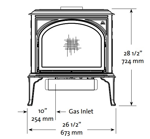
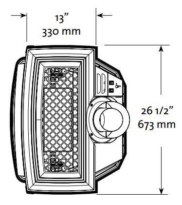
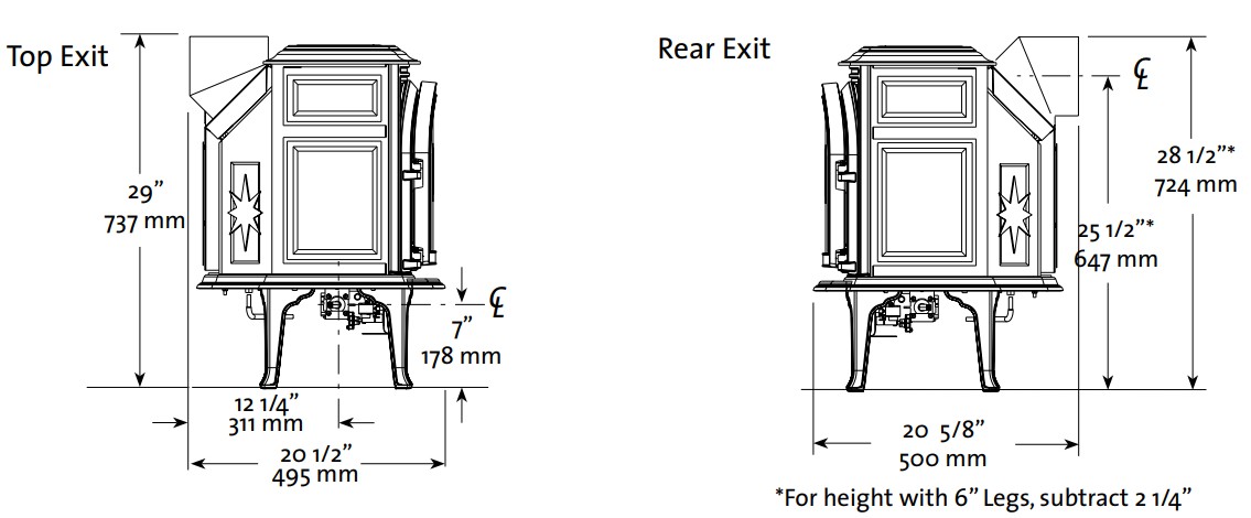
Jøtul GF 400 DV Sebago
Specifications
Input Rates
| Inlet Pressure: | MIN | MAX |
| Natural Gas: | 5.0 WC (1.24 kPa) | 7.0 WC (1.74 kPa) |
| Propane: | 12.0 WC (2.99 kPa) | a14.9 WC (3.71 kPa) |
| Manifold Pressure: | MIN | MAX |
| Natural Gas: | 1.2 WC (.30 kPa) | 3.8 WC (.95 kPa) |
| Propane: | 2.9 WC (.722 kPa) | 11.0 WC (2.74 kPa) |
- SIT Nova 821 Millivolt System– Piezo Ignitor, Standing Pilot
- Steady State Efficiency: NG – 72.49% LP – 75.60%
- AFUE Efficiency: NG – 64.87% LP – 66.88%
- CSA P4. 1-15: Fireplace Efficiency: 63.18%
- Ambient Temperature Range: 32 – 212°F (0 – 100°C)Nova 821 High-Temp Valve
THIS FIREPLACE IS SHIPPED FROM THE FACTORY FOR USE WITH NATURAL GAS ONLY. IF USE WITH PROPANE IS DESIRED, THE APPLIANCE MUST FIRST BE CONVERTED USING THE FUEL CONVERSION KIT PROVIDED, #155351. CONVERSION SHOULD BE MADE BEFORE THE APPLIANCE IS INSTALLED. SEE PG. 16.
General Information
- THIS HEATER MUST BE INSTALLED AND MAINTAINED BY A QUALIFIED SERVICE AGENCY.
- The installation and repair of this appliance must be done by a qualified service person. Failure to properly install and maintain this heater could result in an unsafe or hazardous installation, which may result in a fire, explosion, property damage, personal injury or loss of life.
- This appliance should be inspected before use and at least annually. More frequent cleaning may be required due to excessive lint from carpeting, bedding material, etc. It is imperative that control compartments, burners, and circulating air passageways of the appliance be kept clean.
- THIS APPLIANCE MUST NOT BE CONNECTED TO A CHIMNEY OR FLUE SERVING ANY OTHER APPLIANCE.
- The installation must conform to local codes. Your local Jøtul dealer can assist you in determining what is required in your area for a safe and legal installation. Some areas require a permit to install a gas-burning appliance. lways consult your local building inspector, or authority having jurisdiction, to determine what regulations apply in your area.
- CODE COMPLIANCE: Your local officials have final authority in determining if a proposed installation is acceptable. Any requirement that is requested by the local authority having jurisdiction, that is not specifically addressed in this manual, defaults to local code. In the absence of local codes, the installation requirements must comply with the current National codes. In the U.S., these requirements are established in the National Fuel Code, ANSI Z223.1.(NFPA 54). In Canada, the codes have been established in the CAN/CGA B149 Fuel Installation Code.
- Installer l’appareil selon les codes ou reglements locaux, ou, en l’absence de tels reglements, selon less Codes d’installation CAN/CGA-B149.
- DO NOT OPERATE THIS STOVE IF ANY PART HAS BEEN UNDERWATER. Call a qualified service technician to inspect the heater and to replace any part of the control system and any gas control which may have been underwater.
- Ne pas se servir de cet appareil s’il a ete’ plonge dans l’eau, completement ou en partie. Appeler un technicien qualifie pour inspecter l’appareil et remplacer toute partie du syste’me de control et toute commande qui ont ete plonges dans l’eau.
Glass PanelDo not operate this appliance with the glass front removed, cracked, or broken. Replacement of the glass should be done by a licensed or qualified service person. Only remove glass for routine service. Always handle the glass carefully.
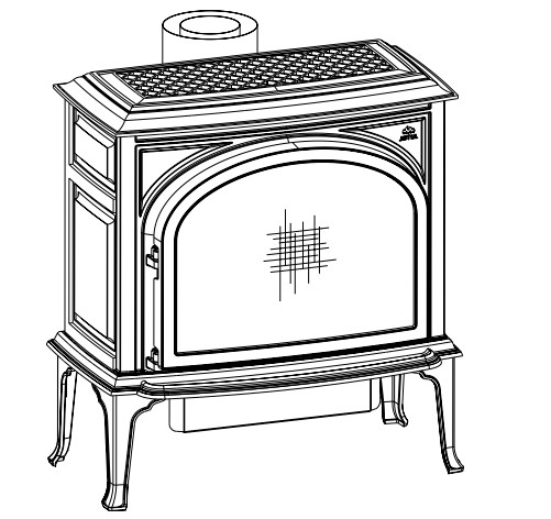
Unpacking your stove
- Remove the Top Plate of the stove by simply lifting it straight off of the stove body.
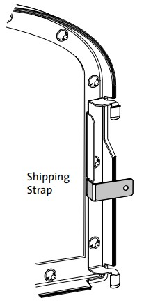
- SAFETY BARRIER SCREEN: This appliance is equipped with a Certified Barrier Screen that must be installed before operating the unit. The barrier is secured to the stove shipping pallet. Remove those two screws and use pliers to break off each perforated shipping the strap from both screen frame attachment brackets as shown here in grey.
- To open the firebox, disengage the two Glass Frame Latches located on top of the firebox. Pull each handle forward to clear the latch from the notch in the frame.

Familiarize yourself with the installation requirements specified in this manual, before beginning the installation.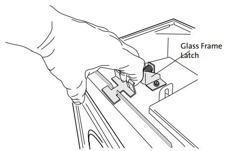 Hardware Bag Contents
- Fuel Conversion Kit – LP ……………………………… 155351
- Ember Bag, 4 oz. ……………………………………….. 129123
- Rock Wool, 1 oz, …………………………………………..157259
Safety Information
- Due to the high operating temperatures, this appliance should be located out of traffic and away from furniture and draperies. Maintain proper clearance to combustible mantels and fireplace trim.
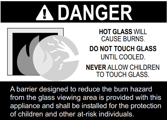
- Children and adults should be alerted to the hazards of high surface temperatures and should stay away to avoid burns or clothing ignition.
- Young children should be supervised while they are in the same room as the appliance. Toddlers, young children and others may be susceptible to accidental contact burns. A physical barrier, such as a child guard, is recommended to be used if there are at-risk individuals in the house. To restrict access to a fireplace or stove, install an adjustable safety gate to keep toddlers, young children, and other at-risk individuals out of the room and away from hot surfaces.
- A barrier designed to reduce the risk of burns from the hot viewing glass is provided with this appliance and shall be installed for the protection of children and other at-risk individuals.
- If the barrier becomes damaged, the barrier shall be replaced with the manufacturer’s barrier for this appliance. See fig. 72, page 34 for part numbers.
- Any safety screen, guard, or barrier removed for servicing an appliance must be replaced prior to operating the appliance.
- Clothing or other flammable materials should not be placed on or near the fireplace.
- Never allow anyone to use the fireplace if they are unfamiliar with its operation.
- NEVER store or use gasoline or any other flammable vapors or liquids in the vicinity of this appliance.
- Never burn any solid materials (wood, cardboard, paper, coal, etc.) in this appliance. Use with natural gas or propane fuel ONLY.
- Do not slam or strike the glass panel.
- This appliance is NOT for use with aftermarket glass doors.
- Wear gloves and safety glasses while installing or performing maintenance procedures on this appliance.
LocationIn selecting a location for the stove, consider thefollowing points:
- Heat distribution
- Vent termination requirements
- Gas supply line routing
- Traffic areas, furniture, draperies, etc.
The GF 400 DV MV may be located on or near conventional construction materials, however, proper clearance to combustibles must be maintained in order to provide adequate air circulation around the appliance. Also, it is important to provide adequate access around the stove for servicing and proper operation. The clearance and hearth specifications listed in this manual are the minimum requirements for combustible material. A combustible material is anything that can burn (i.e. sheetrock, wallpaper, wood, fabrics, etc.). These surfaces are not limited to those that are visible and also include materials that may be located behind non-combustibles. If you are not sure of the combustible nature of a material, consult your local fire officials. Remember, “Fire Resistant” materials are considered combustible: they are difficult to ignite but will burn. Also, “fire-rated” sheetrock is considered combustible.
Hearth Requirements
This appliance CANNOT be installed directly on carpeting, vinyl, linoleum or Pergo. If this appliance will be installed on any campus- ® table material OTHER THAN WOOD, a floor pad must be installed that is either metal, wood, ceramic, stone, or a listed hearth pad. This floor protection must extend the full width and depth of the appliance. It is not necessary to remove carpeting, vinyl or linoleum from underneath the floor protection. See fig. 1.Figure 1. Minimum Hearth Protection.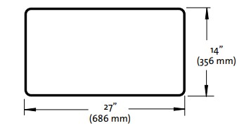
Stove and Vent Clearance Requirements
The clearances specified and diagrammed here are established from the stove body. The safety barrier has no effect on clearances to combustible material.
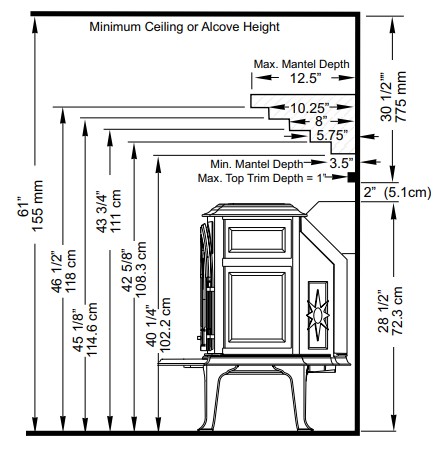
Minimum Clearances from the Stoveto Combustibles: See figs. 2-4.
Rear: 2” (51 mm)Ceiling: 32 1/4” (819 mm)Corner: 2” (51 mm)Sides: 3” (76 mm)
Figure 2. Parallel Installation Clearances.Figure 3. Corner Clearances.

Figure 4a. Mantel and Trim Clearance specifications. The back of the bottom plate is flush with the fireplace face. Subtract 2 1/4” with Short Legs.
Minimum Clearances from the Vent Pipe to Combustibles:Horizontal Run:Off the top of the pipe 2” (51 mm)Off the sides and bottom 1” (25 mm)Vertical Run:All sides 1” (25 mm)
Figure 4b. Stove is installed with the top plate flush with the fireplace face.
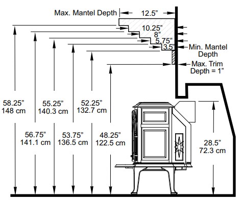
Figure 4c. Stove is installed recessed halfway into the fireplace. The top plate extends 6.5” forward of the fireplace face.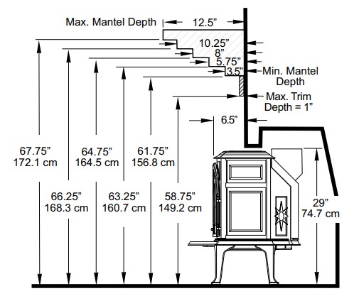
| Alcove InstallationMaximum Alcove Depth: 24” (61 cm)Minimum Alcove Width: 31 3/4” (80.6 cm)Minimum Ceiling Height: 61”(155 cm)With Short Legs (6”) : 59” (150 cm)Alcove dimensions result from test configurations, not stove clearance specifications. |
Venting Requirements
This appliance may be installed with a vertical or horizontal termination and must conform to the configuration requirements described below.
This appliance is approved for use with vent systems from the following manufacturers:
- M&G DuraVent, Inc. (Direct Vent Pro Series)
- Metal-Fab Sure-Seal DV
- American Corporation
- Security Vent Ltd
- Selkirk Metalbestos
- International Chimney Corp. (ExcelDirect)
- Bernard Delsin Mfg. (ProForm)
- Olympia Chimney Supply, Inc. (Ventis Direct Vent)
Use parts of one manufacturer only – DO NOT MIX VENT COMPONENTS FROM DIFFERENT MANUFACTURERS IN THE SAME SYSTEM.Installation of any components not manufactured or approved by Jøtul or failure to meet all clearance requirements will void all warranties and could result in property damage, bodily injury, or serious fire.
The approved vent configurations described in this manual are derived from extensive testing under controlled laboratory conditions. Gas appliance performance can be negatively affected by variables present in the installation environment, i.e: atmospheric pressure, strong prevailing winds, adjacent structures and trees, snow accumulation, etc. These conditions should be taken into consideration by the installer and stove owner when planning the vent system design.
IMPORTANT
- JOINT SEALING REQUIREMENT: APPLY A 1/8” BEAD OF HIGH-TEMPERATURE (750°F) SEALANT TO THE MALE SECTION OF THE INNER VENT PIPE. THE CEMENT SHOULD FORM A SEAL BETWEEN THE INNER AND OUTER PIPES.DO NOT USE SILICONE SEALANT.
- NEVER MODIFY ANY VENTING COMPONENT, OR USE ANY DAMAGED VENTING PRODUCT.
- THE GAS APPLIANCE AND VENT SYSTEM MUST BE VENTED DIRECTLY TO THE OUTSIDE OF THE BUILDING AND NEVER ATTACHED TO A CHIMNEY SERVING A SOLID FUEL OR GAS-BURNING APPLIANCE. EACH DIRECT VENT GAS APPLIANCE MUST HAVE ITS OWN SEPARATE VENT SYSTEM. COMMON VENT SYSTEMS ARE PROHIBITED.
- IF THE VENTING SYSTEM IS DISASSEMBLED FOR ANY REASON, REINSTALL PER THE INSTRUCTIONS PROVIDED FOR THE INITIAL INSTALLATION.

Vent RestrictionThis appliance is equipped with Restrictor Plates which enable you to regulate the flow of incoming combustion air and exhaust gas. The plates prevent an overly strong draft that can cause poor combustion and a weak flame picture. Follow the guidelines below, and on the following pages, to determine the correct restrictor-plate setting for your particular installation configuration.]
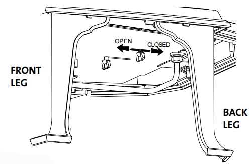
Intake Air Restrictor
This plate is located at the rear of the firebox behind the burner plate. It is set in a CLOSED position at the factory and should be left there for most vent configurations. It should be opened only for snorkel terminations and some short-run horizontal terminations as specified on the following pages. To adjust the Air Restrictor to the OPEN position, locate and loosen the wing nut under the burner and push it back as far as it will go. See Fig. 6.
Exhaust Restrictor
The Exhaust Restrictor is an adjustable shutter located at the top of the firebox. It is adjusted by moving a pivot pin into one of four positions. It is set in the FULLY OPEN position at the factory. See Fig.7.
Use the chart in Table 1 to determine the correct position for your installation and follow the instructions below to adjust it if necessary.Additional restrictions may be needed depending on the overall vent height. Use Simpson Dura-Vent Restrictor Disk #929.
Adjusting Exhaust Restrictor Plate:
- Remove the Top Plate.
- Locate the pivot pin at the left side of the firebox top. Loosen the wing nut on the pivot pin and push the pin to the left to disengage it from the current setting position. Move the pin toward the rear and then right to engage it in the appropriate position indicated on the firebox. See fig. 7.
- Tighten the lock nut and replace the Top Plate.
Figure 6. Adjusting the Air Inlet Restrictor plate – The view is from the right side of the stove.

Vertical Vent Termination
This appliance can be vertically vented through a ceiling or to a roof termination with the following guidelines:
The termination should fall within the shaded areas of the grids depicted in the Vent Window diagrams on pages 10-11.Maximum Vertical run should not exceed 35 ft. (10.66 m).
- Minimum Vertical run must be at least 8 ft. (2.43 m).
- Max. Colinear Horizontal run is 2 ft. (61 cm).
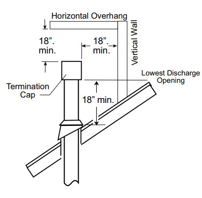
- Vent Terminus Clearance: In no case shall any discharge opening on the cap be less than 18 in. (610 mm) horizontally from the roof surface.
- Steep roofs, nearby trees, and predominantly windy conditions can contribute to poor draft and/or promote down-draft occurrences. Increasing the height of the vent may alleviate these conditions.
- Use Wall Straps to support an offset pipe run at threefeet intervals to avoid excessive stress on the offsets.
- Elbows: Four 45°, or two 90° elbows may be used. Do not include the 45° elbow attached to the stove. Whenever possible use 45° elbows instead of 90° elbows as they are less restrictive to exhaust gas and intake airflow.
- A firestop is required at every floor. The opening should be framed to 10″ X 10″ inside dimension.
- Any venting that is exposed above the first floor, regardless of attic space or living space, must be enclosed. Always maintain the required 1″ clearance from all sides of the vertical vent system.
Figure 7. Adjusting the Exhaust Restrictor plate – Top Plate removed. Viewed from the front of the stove.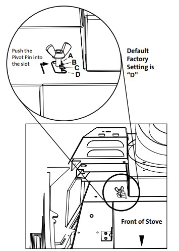
Figure 8. Vertical vent termination height above the roof.
Vent Termination Zones – Natural Gas
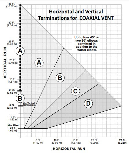
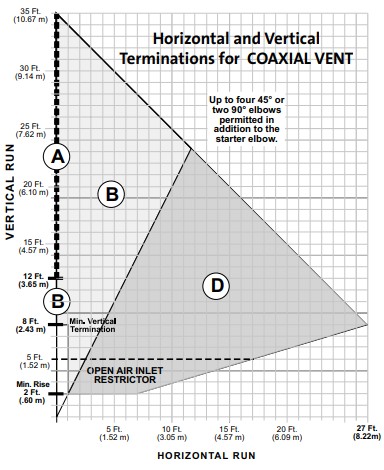
Figure 9. Coaxial Vent Termination Window / NG
- ALL VENTING MUST TERMINATE (END) WITHIN ONE OF THE SHADED AREAS.
- SET STOVE EXHAUST RESTRICTOR TO THE POSITION THAT CORRESPONDS TO THE VENT TERMINATION AREA IN THE DIAGRAM ABOVE.
- ALWAYS MAINTAIN THE PROPER CLEARANCES TO COMBUSTIBLES.
- Up to four 45° or two 90° elbows may be used in addition to the starter elbow. THE HORIZONTAL RUN MUST BE REDUCED BY 5 FEET FOR EACH ADDITIONAL ELBOW, WHETHER 45° OR 90°.
 ALL VENTING MUST TERMINATE (END) WITHIN ONE OF THE SHADED AREAS.
The circled letter designations in the vent diagram correspond to the Exhaust Restrictor Setting on the stove. First, determine which vent termination zone is appropriate for your installation and fuel type, then adjust the restrictor to the corresponding position as shown in Figure 7, page 9.
Figure 10 . Colinear Termination / NG
- VENTING MUST TERMINATE (END) WITHIN THE SHADED AREA.
- Adjust the Exhaust Restrictor to position B for any NG colinear termination.
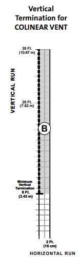 VENTING MUST TERMINATE (END) WITHIN THE SHADED AREA.
Vent Termination Zones – Propane
Figure 11. Coaxial Vent Termination Window / LP
- VENTING MUST TERMINATE (END) WITHIN ONE OF THE DESIGNATED AREAS. ZONE “A” IS FOR VERTICAL TERMINATIONS ONLY.
- SET STOVE EXHAUST RESTRICTOR TO THE POSITION THAT COR- RESPONDS TO THE VENT TERMINATION AREA IN THE DIAGRAM ABOVE.
- OPEN-AIR INLET RESTRICTOR FOR TERMINATIONS 5 FT AND UNDER. SEE FIG. 6, PAGE 9.
- ALWAYS MAINTAIN THE PROPER CLEARANCES TO COMBUSTIBLES.
- Up to four 45° or two 90° elbows may be used in addition to the starter elbow. THE HORIZONTAL RUN MUST BE REDUCED BY 5 FEET FOR EACH ADDITIONAL ELBOW, WHETHER 45° OR 90°.
The circled letter designations in the vent diagram correspond to the Exhaust Restrictor Setting on the stove. First, determine which vent termination zone is appropriate for your installation and fuel type, then adjust thestove restrictor plate to the corresponding position as shown in Figure 7, page 9.
Figure 12. Colinear Termination / LP
- VENTING MUST TERMINATE (END) WITHIN THE SHADED AREA.
- Adjust the Exhaust Restrictor to position C for a straight vertical colinear termination.
- Adjust the Exhaust Restrictor to position D for a vertical colinear termination with maximum 2 ft. offset.
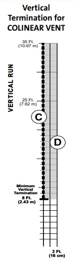 VENTING MUST TERMINATE (END) WITHIN THE SHADED AREA.
Co-linear Vent InstallationThis appliance may be vented through a masonry or Class A prefabricated chimney using a Co-linear Flexible Vent system approved for use with a solid-fuel burning fireplace. When installed in the manner described below, this system can improve the performance of the appliance in cold climate situations, as well as simplify the vent installation. See fig. 13.
These installation requirements must be followed:
- Use the guidelines for Co-linear Vent Termination appropriate for your gas type on pages 10 – 11.
- Prior to the installation the chimney flue must be thoroughly cleaned and inspected by a qualified chimney service person.
- In a masonry chimney, a fireclay liner must be present the entire length of the chimney.
- Prefabricated chimneys must be UL 103 or ULC S-629 listed and have a minimum INSIDE diameter of 6 inches, (150 mm).
- No appliance can be installed into a chimney flue serving any other appliance of any kind.
- THE AIR INTAKE FLEX PIPE MUST EXTEND 6 FEET BEYOND THE DAMPER AREA OF THE FIREPLACE.
- If the intake flex duct does not extend the full length of the chimney and connect to both the unit and the termination cap, A METAL BLOCK OFF PLATE MUST BE CONSTRUCTED AND INSTALLED BOVE THE UNIT PRIOR TO THE END OF THE INTAKE FLEX AND MUST COMPLETELY SEAL THE CHIMNEY FLUE FROM THE ROOM.
Consult with the local code authority having jurisdiction before proceeding with this type of installation.Refer to the vent manufacturer’s instructions for specific installation requirements.
WARNING: FAILURE TO POSITION THE PARTS AND STOVE IN ACCORDANCE WITH THESE DIAGRAMS OR FAILURE TO USE ONLY PARTS SPECIFICALLY APPROVED FOR USE WITH THIS APPLIANCE MAY RESULT IN PROPERTY DAMAGE OR PERSONAL INJURY. BE SURE TO MAINTAIN THE PROPER CLEARANCES TO COMBUSTIBLES AS DEFINED IN THIS MANUAL AND IN THE INSTRUCTIONS PROVIDED WITH EACH VENT COMPONENT.
Figure 13. Co-linear Adaptor installed through a masonry chimney. The components shown may differ somewhat from manufacturer to manufacturer.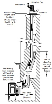
Figure 14. Simpson Dura-Vent #923GCL Co-linear Adaptor is shown – other manufacturer’s components may differ. Subtract 2 1/4” for Short Legs.

Masonry or Prefabricated Chimney ConversionThis appliance is approved for use with listed chimney conversion kits from any of the manufacturers listed on page 8. These kits are for use in a masonry chimney or a prefabricated solid fuel-listed chimney. See fig. 15. These installation requirements must be followed:
- Use the guidelines for Coaxial Vent Termination appropriate for your gas type on pages 11 – 12.
- In a masonry chimney, a fireclay liner or listed steel liner must be present the entire length of the chimney.
- Chimney height should not exceed 35 ft. (10.66 m).
- The liner must have an inside dimension of 6” round or greater.
- Prefabricated chimneys must be UL 103 or ULC S-629 listed and have a minimum INSIDE diameter of 6 inches, (150 mm). Prefabricated chimneys must be listed for the specific Chimney Conversion Kit you choose.
NOTICETHE USE OF AN EXISTING CHIMNEY AS AN AIR INTAKE IS NOT COVERED UNDER THE ANSI Z21.88-1999-CSA 2.33-M99 TEST METHODS AND RESULTING IN ITS/WHI PRODUCT CERTIFICATION. THE CODE AUTHORITY HAVING JURISDICTION MUST BE CONSULTED PRIOR TO PROCEEDING WITH THIS INSTALLATION METHOD.
Figure 15. Vent System through a masonry chimney using a chimney conversion kit. May also be used in listed prefabricated chimneys. Drawing is for illustrative purposes only – DO NOT VENT TWO APPLIANCES INTO A SINGLE CHIMNEY.
Horizontal Termination
- Any horizontal termination must fall within the shaded portion of the vent window graph illustrated in figs. 9 or 11. For Snorkel Terminations, see below.
- Any horizontal termination except a snorkel termination must include:
- Minimum rise of 2 ft.
- Minimum horizontal run of 12 in. when the vertical run is less than 8 ft.
- Maximum rise of 35 ft.
- Maximum horizontal run of 27 ft.
- Up to four 45° or two 90° elbows may be used in addition to the starter elbow. The horizontal run must be reduced by 5 feet for each additional elbow, whether 45° or 90°.
- Follow all termination clearance guidelines as specified in fig. 19.
- The horizontal termination cap must maintain a 3″ clearance to any overhead combustible projections 2 1/2″ or less. It must also maintain 12″ clearance from projections exceeding 2 1/2″. See fig. 20.
- Wall Cut-out Opening: A minimum 10″ X 10″ (250 mm x 250 mm) square hole is required for proper pipe clearances through a combustible wall. Use a listed wall thimble for the wall penetration. DO NOT FILL AIR SPACE WITH ANY TYPE OF INSULATION.
- Any horizontal run of vent must have a 1/4″ rise for every foot of run toward the termination cap. NEVER ALLOW THE VENTING O RUN DOWNWARD FROM STOVE TO TERMINATION; DOWNWARD VENT RUNS TRAP HEAT AND CAUSE HIGH TEMPERATURES TO DEVELOP WITHIN THE VENT THAT COULD START A FIRE.
- Install a Vinyl Siding Standoff between the vent termination and an exterior wall covered by vinyl siding material to prevent potential heat damage to the siding.
- Do not recess the termination cap into a wall or siding.
Snorkel Terminations
- THE AIR INLET RESTRICTOR MUST BE SET FULLY OPEN FOR ANY SNORKEL TERMINATION. See Fig. 6, pg. 9.
- With a 14” Snorkel: The horizontal run made directly off the rear of the stove into a 14” snorkel cap should include no more than a single 12” straight section as shown in fig. 17. One 45° Elbow may be used for a corner installation as shown in fig. 18.
- With a 36” Snorkel: The maximum horizontal run may be no more than 6 ft. (182 cm.)
Figure 16.
- Minimum vent for horizontal termination.
- 14” Maximum horizontal run directly off rear of stove with 14” Snorkel termination.

Figure 17. Maximum Horizontal and Vertical Run with 36” Snorkel Termination. Figure 18. Corner Installation with 14” Snorkel Termination.
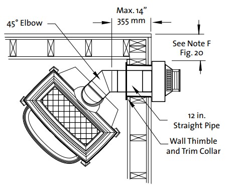 Horizontal Termination Clearance
Figure 19. Vent Terminal Clearances, Canada and the United States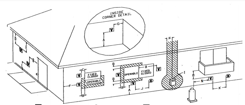 Figure 20. Termination Clearance to overhangs.
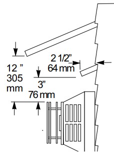
| Canadian Installations 1 | U.S. Installations 2 | ||
| A | Clearance above grade, veranda, porch, deck, or balcony | 12 in. (30 cm) | 12 in. (30 cm) |
| B | Clearance to window or door that may be opened | 12 in. (30 cm) | 9 in. (23 cm) We recommend 12 in. to prevent condensation on a window. |
| C | Clearance to the permanently closed window | 12 in. (30 cm) | 9 in. (23 cm) We recommend 12 in. to prevent condensation on a window. |
|
D |
Vertical clearance to ventilated soffit located above the terminal within a horizontal distance of 2 ft (60 cm) from the centerline of the terminal | 18 in, (46 cm) | 18 in, (46 cm) |
| E | Clearance to unventilated soffit | 12 in,. (46 cm) | 12 in,. (46 cm) |
| F | Clearance to the outside corner | 12 in,. (46 cm) | 9 in. (23 cm) We strongly recommend 12 in. particularly where strong winds prevail. |
| G | Clearance to the inside corner | 12 in,. (46 cm) | 9 in. (23 cm) We strongly recommend 12 in. particularly where strong winds prevail. |
| H | Clearance to each side of the centerline extended above a gas meter or regulator | 3 ft. (91 cm) within a height 15 ft. above the meter/regulator assembly | * |
| I | Clearance to service regulator vent outlet | 3 ft. (91 cm) | * |
| J | Clearance to non-mechanical air supply inlet to building or the combustion air inlet to any other appliance | 12 in. (30 cm) | 9 in. (23 cm) |
| K | Clearance to a mechanical air supply inlet | 6 ft. (1.83 m) | 3 ft. (91) cm above if within 10 ft. (3 m) horizontally |
| L | Clearance above paved sidewalk or paved driveway located on public property | 7 ft. (2.13 m) 3 | * |
| M | Clearance under veranda, porch, deck, or balcony | 12 in. (30 cm) 4 | 12 in. (30 cm) 4 |
| N | Clearance to propane tank relief valve and filler connection | 5 ft. (1.52 m)5 /10 ft. (3.05 m) 6 | 5 ft. (1.52 m)5/10 ft. (3.05 m) 6 |
- In accordance with the current CSA B149.1, Natural Gas and Propane Installation Code.
- In accordance with ANSI Z223.1/MNPA 54, National Fuel Gas Code* For clearances not specified in ANSI Z223.1/NFPA or CSA B149.1, the clearance will be in accordance with local installation codes and the requirements of the gas supplier.
- A vent shall not terminate directly above a sidewalk or driveway which is located between two single-family dwellings and serves both dwellings.
- Permitted only if the veranda, porch, deck, or balcony is fully open on a minimum of two sides beneath the floor.
- Minimum clearance to tanks not filled on site.
- Minimum clearance to tanks filled on-site from the bulk truck.
Mobile Home Installation
This appliance can be installed for use in a mobile home in the U.S. and Canada provided:
- The stove is secured to the floor of the mobile home. Use Jøtul Floor Bracket Kit #750304.
- Provision must be made to secure an electrical ground between the stove and the mobile home chassis.
- The stove is installed in accordance with Title 24 CFR, Part 3280- Manufactured Home Construction andSafety Standard, in the U.S. In Canada, comply with CSA Z240.4, Gas Equipped Recreational Vehicles, and Mobile Housing.
- Always contact your local officials about installation restrictions and requirements in your area.
THIS APPLIANCE MAY BE INSTALLED IN AN AFTERMARKET-KET PERMANENTLY LOCATED, MANUFACTURED (MOBILE) HOME, WHERE NOT PROHIBITED BY LOCAL CODES. THIS APPLIANCE IS ONLY FOR USE WITH THE TYPE OF GAS THAT IS INDICATED ON THE STOVE’S RATING PLATE. A GAS CONVERSION KIT IS PROVIDED WITH THE GF 400 SEBAGODIRECT VENT GAS STOVE.
CET APPAREIL PEUT ETRE INSTALLE DANS UN MAISON PREFABRIQUEE (MOBILE) DEJA INSTALLEE A DEMEURE SI LES REGLEMENTS LOCAUX LE PERMETTENT. CET APPAREIL DOIT ETRE UTILISE UNIQUEMENT AVEC LES TYPES DE GAS INDIQUES SUR LA PLAQUE SIGNALETIQUE. NE PAS L’UTILISER AVEC D’AUTRES GAS SAUF SI UN KITDE CONVERSION CERTIFIE EST INSTALLE.
Fuel Conversion
This appliance is shipped from the factory equipped to burn NATURAL GAS only. If PROPANE gas is to be used as fuel, the appliance must first be converted for use with propane. Use Propane Conversion Kit 155351, supplied with the appliance. Order and install NG Conversion Kit 155352 to change back to use with natural gas.
WARNING:THE CONVERSION KIT IS TO BE INSTALLED BY AN AUTHORIZED SERVICE TECHNICIAN IN ACCORDANCE WITH THE MANUFACTURER’S INSTRUCTION AND ALL CODES AND REQUIREMENTS OF THE AUTHORITY HAVING JURISDICTION. FAILURE TO FOLLOW THESE INSTRUCTIONS COULD RESULT IN SERIOUS INJURY OR PROPERTY DAMAGE. THE QUALIFIED AGENCY PERFORMING THIS WORK ASSUMES RESPONSIBILITY FOR THIS CONVERSION.IN CANADA:THE CONVERSION SHALL BE CARRIED OUT IN ACCORDANCE WITH THE REQUIREMENTS OF THE PROVINCIAL AUTHORITIES HAVING JURISDICTION AND IN ACCORDANCE WITH THE REQUIREMENTS OF THE CAN1-B149.1 AND .2 INSTALLATION CODE.
Tools required:
- 1/2” open-ended wrench or deep-well socket, Torx T20 or slotted screwdriver, 4 mm Allen wrench.Conversion Kit Contents:
- 1, regulator tower labeled for propane
- 3, regulator tower screws
- 1, burner orifice (#33 for NG, 1.65 mm for LPG)
- 1, pilot orifice (#51 for NG, #30 for LPG)
- Label A – to be completed and applied to the back of the stove
- Label B – apply to the stove’s Rating Plate
- Small valve label – apply to valve body Conversion instructions are also shipped in the stove with the conversion kit.
Fuel Conversion Procedure
Refer to fig. 47, Illustrated Parts Breakdown, to identify the part numbers below.
- Turn off gas supply to stove.
- Remove the stove Top Plate (41).
- Disengage the two Glass Frame Latches at the top of the firebox. See illustration on page 5. Carefully lift the glass panel up and out of the stove.
- If installed, remove the Embers and Log Set using care not to damage the fragile log parts.
- Lift out the Burner Skirt (33). Tilt the skirt at an angle to clear the firebox sides and front.
- Reach under the stove and remove the Air Shutter wingnut from its stud. As you face the right side, it is the one closest to you. See fig. 21.
- Lift out the Burner Plate: NOTE: There are no screws securing the Burner to the floor of the firebox. Pull the Air Shutter forward and lift the burner together with the shutter up and out of the stove as a unit. See fig. 22.
- Change the Main Burner Orifice. See fig. 23. Using a 1/2” open-ended wrench or deep-well socket remove the burner orifice from its brass elbow housing and replace with the appropriate orifice supplied in the kit. #33 for NG 1.65 mm for LP
- Replace the Air Shutter with its gasket and push it all the way back to allow replacement of the Burner Plate. 10. Replace the Burner Plate. Engage the Air Inlet Tube with the Air Shutter and burner orifice. Properly seated, the burner plate will be engaged at its front corners with the two support brackets located at the front of the firebox.• Replace the wingnut loosely on the air shutter stem under the stove. Air shutter adjustment will be donelast.
- CHANGE THE PILOT ORIFICE: From within the firebox, remove the Pilot Head by pulling it straight up from the pilot base. See fig. 25. Using the 4 mm Allen wrench that is included with the conversion kit, unscrew the pilot orifice (counterclockwise). Replace with the appropriate orifice:# 51 for natural gas#30 for propane gas
- Tighten orifice into the base of the pilot assembly. To prevent bypass leaks, be sure the orifice is secured tightly and flush with the base. Replace the pilot head by pushing it down onto the pilot base.
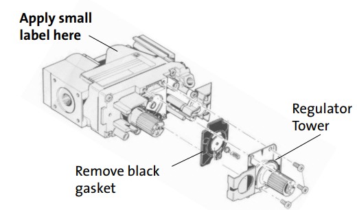
- Replace the Variable Regulator. Using a Torx T-20 screwdriver, remove the three screws from the front of the valve regulator. See fig. 26.
Figure 21. Locate and remove the Air Shutter wingnut from under the right side of the stove.
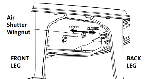 Figure 22. Remove the Air Shutter and Burner as a unit.
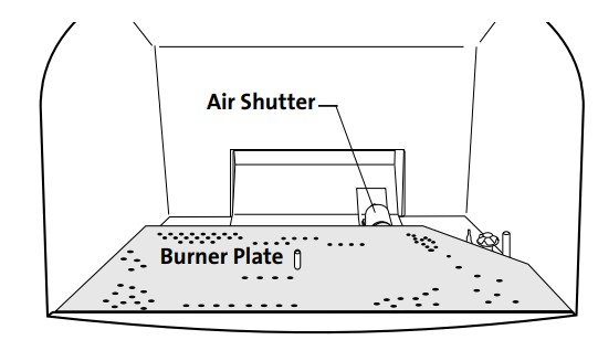 Figure 23. Change the Burner Orifice.
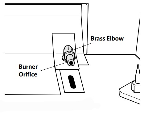 Figure 24. Air Shutter Setting

14. Remove the Regulator Tower, Gasket, white plastic disk, and Spring.15. Install the new regulator: Be sure the new gasket is properly positioned and tighten screws securely.16. Install the identification labels to the stove so that they can be seen by any person that may be servicing the stove.Label A: apply to the back of stove. Label B: apply to stove’s rating plate. Small valve Label: apply to valve.17. Reassemble the stove, apply gas to the system and check for leaks using a soapy water solution.18. Adjust the Air Shutter: CAUTION! USE WORK GLOVES. SURFACES MAY BE HOT!You will need to adjust the shutter to the position that supplies the correct amount of air mixture to achieve the best flame picture with your particular installation. Start with the shutter stem at the midway position in the slot in the bottom of the stove. See fig. 21. Pushing the stem back will restrict air while pushing it forward will open the shutter. Too much air will produce a lighter flame, while too little will promote long, dark flames and may promote shooting. Make adjustments in small increments. With some experimentation, you will find the shutter position that works best for your installation.
Figure 25. Pilot orifice removal and replacement.
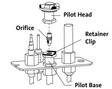 Figure 26. Regulator assembly.
NEVER USE AN OPEN FLAME TO CHECK FOR GAS LEAKS.Correct gas pressure is essential for the efficient and safe operation of this appliance. Correct gas pressure must be established at the time of installation. For more details, see the Gas Pressure section of this manual (page 19). ALWAYS REFER TO THE LIGHTING INSTRUCTIONS ON THE INSIDE BACK COVER OF THIS MANUAL WHEN LIGHTING YOUR STOVE.
Gas Supply Connection
Connect the gas supply line to the stove, before installing the optional Blower. If the blower will be installed, use a 45° elbow off the control valve to create clearance required for the blower installation.
The gas supply line connection is made to the left side of the valve. The gas supply line should be 3/8” npt with a 1/2” diameter supply, or the appropriate size to provide sufficient gas pressure to the valve regardless of the input setting.The use of Flexible Gas Appliance Connectors is acceptable in many areas in the U.S. However, Canadian methods vary depending on the local code. ALL INSTALLATIONS MUST COMPLY WITH LOCAL CODE OR IN THE ABSENCE OF LOCAL CODE, MUST COMPLY WITH THE MOST RECENT EDITION OF THE NATIONAL FUEL GAS CODE ANSI Z223.1/NFPA 54 OR CAN-B149.All codes require a gas shut-off valve (gas cock) and union, to be installed in the supply line, and in the same room as the appliance. This allows for the disconnection of the stove for servicing and maintenance. See fig.27.
Figure 27. Supply valve coupling. A T-HANDLE GAS COCK IS REQUIRED IN MASSACHUSETTS TO COMPLY WITH CODE 248CMR.
Secure all joints tightly using appropriate tools and sealing compounds. For propane, units be sure to use compounds that are propane resistant. Turn on the gas supply and test for gas leaks using a soapy water solution. Never use an open flame to check for leaks.
Leak test:
- Mix a 50-50 solution of water and dish soap.
- Light appliance- see lighting instructions on the inside back cover of this manual or on the stove’s rating plate.
- Brush or spray all joints and connections with the soapy water solution.
- If bubbles appear at any connection or seam or a gas odor is detected, immediately urn gas control knob to the OFF position.
- Tighten or reconnect the leaking joint and retest for any gas leaks.
Gas Pressure
Correct gas pressure is essential for the efficient and safe operation of the GF 400 DV MV gas stove. It is important that the correct pressure is established at the time of the installation. Proper gas pressure provides aconsistent flow of gas to the appliance and instrumental in checking for gas leaks. Pressure Test: Attach a manometer to the appropriate test point on the valve. See fig. 28. The gauge connections are located on the front of the valve under the On/Off/Pilot- knob. Gauge connections are identified by:E – for Inlet or SupplyPressure (the amount of gas coming to the valve.)A – for Manifold Pressure (the amount of gas that is coming out of the valve to the burner.) ALWAYS TEST PRESSURES WITH VALVE CONTROL KNOB SET ON HIGH.
Figure 28. Pressure test points
| INLET GAS PRESSURES
(inches water column) MIN MAX NATURAL GAS 5.0 7.0 PROPANE 12.0 14.9 The appliance and its appliance main gas valve must be disconnected from the as supply piping system during any pressure testing on that system at test pressures in excess of 1/2 psig (3.5 kPa). The appliance must be isolated from the gas supply line by closing its individual manual gas shut-off valve (gas cock) during any pressure testing of the gas supply piping system that is equal to or exceeds pressures of 1/2 psig (3.5 kPa). MANIFOLD PRESSURES (inches water column)MIN MAX NATURAL GAS 1.2 3.8PROPANE 2.9 11.0 |
High Altitude Adjustment
Installations located at altitudes from 2000 – 4500 ft. (610 m -1370 m) DO NOT require adjustment for altitude. DO NOT DERATE THIS APPLIANCE FOR ALTITUDE.
Flame Appearance / Air Shutter Adjustment
This appliance is shipped from the factory equipped to burn natural gas with the air shutter setting half-open. Be aware, however, that this initial setting may not provide the optimal flame picture in your particular installation. No single setting will be appropriate for all vent configurations, fuel types, or installation environments. The air shutter setting can also be adjusted to achieve the desired flame appearance. Flame appearance is a matter of individual preference, however, most people enjoy a warm yellowish flame.
Too much air – the appliance will generate a flame that is blue and transparent or an “anemic” flame.Too little air – the appliance may generate very long yellow flames resulting in soot. Sooting produces black deposits on the logs, on the inside walls of the appliance, and potentially, on the exterior termination cap. Sooting is caused by incomplete combustion and lack of combustion air entering the air shutter opening.
To adjust the air shutter: CAUTION! USE WORK GLOVES. SURFACES MAY BE HOT!
1. Reach under the right side of the stove and loosen the wingnut located closest to you. See fig. 29. Slide the wingnut stem forward to open the air shutter and increase air. Slide the shutter stem back to decrease the air supply.2. Tighten the wingnut to secure the shutter at the desired setting.3. Operate the burner for 30 minutes on the HIGH setting, observing the flame continuously. If the flame appears weak, slow, or sooty, adjust the air shutter to a more open position as described above until the flame is as desired. Make adjustments in small increments and allow the burner to settle in before making further adjustment
WARNING: AIR SHUTTER ADJUSTMENTS SHOULD ONLY BE PERFORMED BY A QUALIFIED PROFESSIONAL SERVICE TECHNICIAN.
Figure 29. Loosen the wingnut to adjust the air shutter stem.
Optional Wall Thermostat or Remote Control
 Optional Wall Thermostat or Remote Control
 Use only a 750 millivolt DC two-wire circuit thermostat with this appliance. The thermostat should be placed in the same room as the heater, typically 5 feet off the floor. Avoid drafty areas or any area that may affect the accuracy of the thermostat.
The thermostat should be connected to the GF 400 DV MV using a minimum of 16 gauge wire with a maximum length of 25 feet of wire.
Connect the two thermostat wire leads to the two lower terminals on the terminal block located directly above the ignitor button. Do not overtighten the connections. IT IS NOT NECESSARY TO DISCONNECT ANY OTHER WIRES. See Fig. 31.For thermostatic operation, the On/Off/T-Stat switch on the back of the stove must be in the T-stat position, and the pilot light must be running, as it is the power source for the thermostat. At the thermostat, the two wires should be connected to the two connection screws on the thermostat base plate per the manufacturer’s instructions.Remote Control
When using a remote, the remote receiver should be wired to the terminal block the same way the thermostatwould be. See the instructions above. Follow the operating instructions included with the Remote Control unit.
CAUTION:LABEL ALL WIRES PRIOR TO DISCONNECTION WHEN SERVICING THE CONTROLS. WIRING ERRORS CAN CAUSE IMPROPER OR DANGEROUS OPERATIONS. ALWAYS VERIFY PROPER OPERATION AFTER SERVICING THE APPLIANCE.
Figure 31. Accessory wiring diagram.
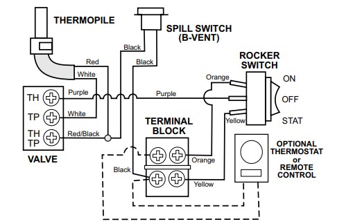
CRITICAL NOTE:THE RED THERMOPILE WIRE MUST BE CONNECTED TO THE VALVE TH/TP TERMINAL TO POWER THE THERMOSTAT.
Log Set Installation
NOTE: If appropriate, install the optional Antique Brick Panel Kit before assembling the log set. The log set must be installed before operating the burner. The log set includes five log pieces, packaged inside the firebox, and a number of ember stones packaged in the Miscellaneous Parts bag. To install the log set, remove the packaging and place the parts on the locator pins inside the firebox as illustrated in figs 32-37. Do not handle the log set with your bare hands. Always wear gloves to prevent skin irritation from the ceramic fibers.
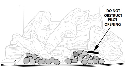
IMPORTANTThe ember stones realistically simulate glowing coals when the burner is operating. These should be spread evenly over the burner plate and around the logs.
TO ENSURE PROPER BURNER FUNCTION, DO NOT OBSTRUCT THE PILOT ASSEMBLY AND BURNER SKIRT OPENINGS WITH EMBER STONES. KEEP EMBERS AWAY FROM PILOTCARRY-OVER PORTS. See fig.37
You do not need to use all of the ember stones. With some experimentation, you will find the arrangement and quantity of embers that work best with your stove. Depending upon the characteristics of your installation, it is possible that too many ember stones can promote sooting on the logs. Adjust the number of ember stones as appropriate to maintain the best overall flame picture and burner performance.
Figure 32. Install Right Log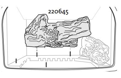
Figure 33. Install Rear Log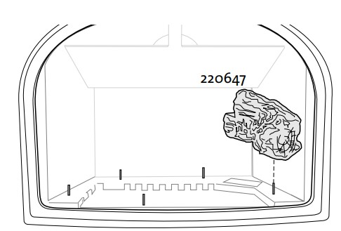
Figure 34. Install Left Log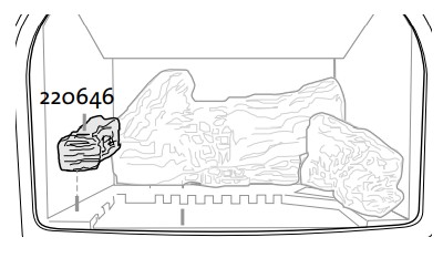 Figure 35. Install Middle Log
 Figure 36. Install Crossover Log
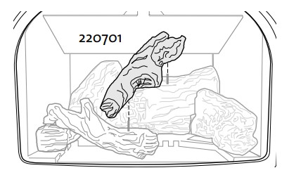 Figure 37. Install Ember Stones
System Check
- PURGING THE GAS LINE: When lighting the appliance for the first time, it will take a few moments to clear the gas line of air. Once this purge is complete, the appliance will operate as described in the lighting instructions. See the inside back cover of this manual or the stove Rating Plate attached the bottom of the stove. Subsequent burner starts will not require purging the gas line unless the supply line is shut off.
- PILOT FLAME: You can monitor the pilot flame through the viewport located at the rear of the Right Log. The pilot flame should be steady – not lifting or floating. The flame should be blue in color around the pilot hood, with traces of yellow toward the outer edges. The pilot flame should engulf the top 3/8” of the thermopile (to generate millivolt current) and the top 1/8” of the thermocouple. The pilot flame should project out of all three pilot hood ports 1” and project over to the burner plate carry-over ports. See fig. 38 and 38a.
DO NOT ATTEMPT TO ALTER THE FLAME APPEARANCE BY POSITIONING THE GAS VALVE CONTROL IN ANY OTHER THAN THE FULL “ON” POSITION.
3. BURNER ADJUSTMENT: This stove is equipped with a variable gas control valve that allows easy adjustment of the flame height appearance and heat output. To adjust the flame between the HI and LOW setting, rotate the HI/LOW knob, located in the center of the valve face. Flame height will adjust approximately 1” to 2” between the LOW and HIGH settings. See fig. 39.
NO SMOKE OR SOOT SHOULD BE PRESENT. CHECK LOG PLACEMENT IF ANY SOOT OR SMOKE IS PRESENT. IF SOOT OR SMOKE PERSISTS, THE AIR SHUTTER MAY NEED TO BE ADJUSTED.
See Air Shutter/Flame Appearance section of this manual for proper air shutter settings and adjustments.Note: the more offsets there are in the vent system, the greater the need for an air shutter adjustment. See page 20.
WARNING:AIR SHUTTER ADJUSTMENTS SHOULD ONLY BE PERFORMED BY A QUALIFIED PROFESSIONAL SERVICE TECHNICIAN.
Figure 38. Proper pilot flame appearance.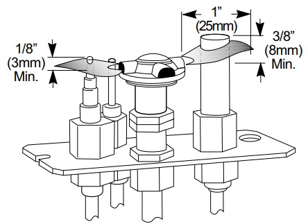 Figure 38a. Proper pilot flame appearance relative to burner carry-over porting.
  Figure 39. Flame appearance on the “high” setting after approximately 15 to 20 minutes burning.
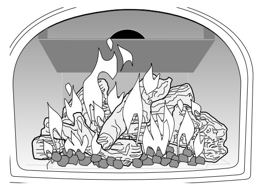
Operation
Familiarize yourself with the controls of the GF 400 DV MV and any other user is also familiar with the controls and operating procedures. Always follow the Lighting Instructions on the inside back cover of this manual and also located on the Rating Plate attached to the back of the stove.
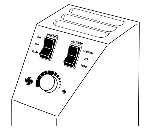
- Once the pilot is lit, the burner operation is controlled by the rocker switch located at the left rear corner of the stove. Use the T-STAT position for the optional thermostatic or remote control functions. See fig. 40.NOTE: The pilot will automatically shut off after seven (7) days if there has been no call for heat during that period. Relight the pilot manually following the instructions on the back cover and rating plate.
- During the first few fires, you may notice odor and/ or smoke from the stove. This is normal and results from the burn-off of manufacturing residue and curing of materials. You may find it helpful to provide additional ventilation and fresh air to alleviate this condition.
- Condensation may occur on the glass upon each lighting of the appliance. This “fog” will disappear as the appliance heats up.
- Keep the controls and the area under the appliance free of debris, vacuum this area frequently. Always keep the appliance area clear and free from combustible materials, gasoline, and other flammable liquids. If a vacuum is used during any service on the stove, ALWAYS be sure the stove is cold and there are NO hot embers.
- Exercise caution when using products having combustible vapors while the pilot light is burning. Always shut off gas supply while servicing the stove.
- CAUTION: DO NOT OPERATE THIS APPLIANCE WITH THE GLASS REMOVED CRACKED OR BROKEN.Replacement of the glass should be done by a licensed or qualified service person. Use only replacement glass provided by your authorized Jøtul dealer. Never use any substitute materials.WARNING: OBSERVE CAUTION WITH THE GLASS. THE GLASS PANEL MAY SHATTER UNEXPECTEDLY IF STRUCK BY AN OBJECT. ALWAYS HANDLE THE GLASS PANEL WITH CARE. WHEN SERVICING THE STOVE ALWAYS PULL THE GLASS ASSEMBLY STRAIGHT UP FOR REMOVAL.
- Clean the glass only when necessary. Wipe the surface with a clean, damp soft cloth. Follow with a dry, soft towel as desired. Take care not to scratch the glass surface.WARNING: DO NOT USE ABRASIVE CLEANERS ON THE GLASS. NEVER CLEAN THE GLASS WHEN IT IS HOT.
Figure 40. Burner Switch and Optional Blower Controls
Maintenance
This appliance and its venting system should be inspected before use and at least annually by a qualified service technician. Use the form on page 30 to keep a maintenance history of your stove.
IMPORTANT:ALWAYS TURN OFF THE GAS SUPPLY TO THE FIREPLACE AND UNPLUG THE FORCED AIR BLOWER BEFORE ANY SERVICE WORK IS PERFORMED ON THE FIREPLACE.Annual Cleaning
Vent SystemThe entire vent system, including the chimney, should be inspected and cleaned every year. If the intake and exhaust venting is disassembled for any reason, it should be reassembled and sealed according to the manufacturer’s instructions provided at the initial installation.
Firebox ComponentsPeriodically inspect the Firebox, Valve Compartment, Convection Airways and optional Blower to BE CERTAIN THAT THE FLOW OF COMBUSTION AND VENTILATION AIR IS UNOBSTRUCTED.
- The firebox should be vacuumed annually to remove any surface build-up. Use a soft brush attachment and handle the logs carefully as they are fragile.
- Inspect the pilot head, thermopile and thermocouple for signs of rust or deterioration and replace any components that do. Check that the pilot head is properly engaged with the throat and is oriented correctly. See fig. 38, page 22.
- Inspect the burner and confirm that all the ports are unobstructed, particularly at the pilot area. Vacuum the burner plate if necessary.
Glass CareClean the glass only when necessary. Wipe the surface with a clean, dampened, soft cloth. Follow with a dry, soft towel. Take care not to scratch the glass surface.
WARNING: DO NOT USE ABRASIVE CLEANERS ON THE GLASS. NEVER CLEAN THE GLASS WHEN IT IS HOT.Gasket InspectionIt is important that the glass gasket be inspected at least annually. Examine the ribbon gasket for signs of deterioration and make sure the gasket has a positive seal. Replace the gasket if necessary. Refer to the replacement parts list on page 29.
NOTE: INSPECT THE GLASS SURFACE FOR SCRATCHES AS THESE CAN WEAKEN THE PANEL TENSILE STRENGTH. REPLACE THE PANEL IF ANY SCRATCHES ARE FOUND. FOR REPLACEMENT, USE THE ONLY JØTUL CERAMIC GLASS PANEL 155553. DO NOT USE ANY OTHER TYPE OF GLASS WITH THIS APPLIANCE.
Glass Panel or Gasket Removal
- Lift the Top Plate off of the stove.
- Release the two Glass Frame Latches. Pull each latch handle forward to disengage the latch from the notches in the glass frame.
- Lift the glass frame all the way up and out of the top of the stove. Lay this assembly on a flat surface, protecting the frame from scratches using a blanket or towel.
- The glass panel is held in place by four compression clips. Use a screwdriver or small pliers to pry these up off the edge of the glass retaining walls. See fig. 41.
- Remove the old gasket material.
Figure 41. Use small pliers to pry the clips off of the glass panel frame.
Glass Panel or Gasket Replacement
- Wrap the new gasketing material evenly around the edge of the glass, peeling back the protective strip to expose the adhesive as you go. Press the adhesive side down onto the glass surface. Do not stretch the gasket.
- Place the gasketed glass within the frame and press each of the retainer clips back into place on the retainer walls.
Figure 42. Wrap the gasket around the glass panel.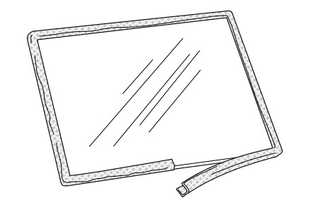
Optional Blower # 156000
Connect the gas supply line to the stove, before installing the Blower. Use a 90° Elbow off the control valve to create clearance required for the blower installation.
- Unpack and check the contents of the blower kit. Contact your dealer if any damage is evident or parts are missing. See fig. 43.
- Attach the Snapchat Bracket to the studs located in the middle of the firebox floor using the two M6 hex nuts and a 10 mm wrench. See fig. 44.
- Attach the Blower Bracket to the stove using the two M6 flange head hex bolts as shown in fig. 44.
- Attach the Duct Deflectors using the two #7 x 1/2” screws together with the finger guard mounting screws already in place. See #7 and #11 in fig. 43.
- Install the Blower with the duct openings oriented up and forward. See fig. 45. Feed the wire harness through the bracket opening and secure the blower to the bracket with the wingscrew.
- Attach either Snapstat wire connector to either Snapstat terminal. See fig. 45.
- Install the Snapchat by sliding it all the way into the slot in the bottom of the Snapchat Bracket as shown in figs. 43 and 45.
- Connect the male wire harness connector to the female wire harness connector already installed in the stove. See fig. 45.
- Connect the power cord to an outlet.
- THIS BLOWER MUST BE ELECTRICALLY GROUNDED IN ACCORDANCE WITH LOCAL CODES OR, IN THE ABSENCE OF LOCAL CODES, WITH THE CURRENT ANSI/NFPA 70, NATIONAL ELECTRICAL CODE OR CSA 22.1-CANADIAN ELECTRICAL CODE.
- THIS UNIT IS SUPPLIED WITH A THREE-PRONG (GROUNDING) PLUG FOR PROTECTION AGAINST SHOCK HAZARDS AND SHOULD BE PLUGGED DIRECTLY INTO A PROPERLY GROUNDED THREE-PRONG RECEPTACLE. DO NOT CUT OR REMOVE THE GROUNDING PRONG FROM THE PLUG.
- ALWAYS DISCONNECT THE POWER SUPPLY WHEN PERFORMING ANY SERVICE ON THE FIREPLACE INSERT.
Figure 43. Blower Kit Components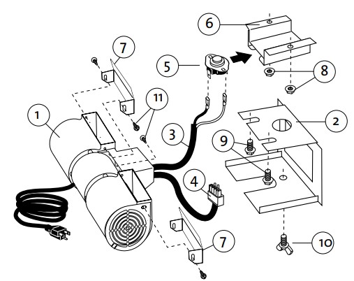 Contents
- Blower
- Mounting Bracket
- Snapchat Wire Harness
- Control Switch Wire Harness
- Snapshat
- Snapchat Bracket
- Blower Duct Deflector (2)
- M6 Hex Head Flange Nuts (2)
- M6 x 12 Hex Head Flange Bolts (2)
- M6 x 12 Wingscrew
- #8 x 1/2” Phillips screw (2)
Tools Required
- 10 mm wrench
- short Phillips screwdriver
- Safety Glasses
- Work Gloves
Figure 44. Attach Snapstat and Blower Brackets.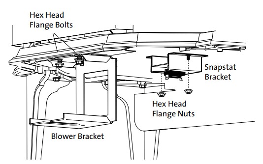 Figure 45. Attach Blower to the Mounting Bracket with the wingscrew and connect wires to Snapstat and female control quick connect.

Blower Operation
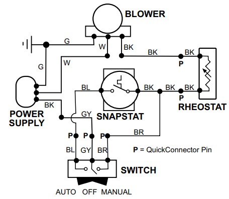
The optional variable-speed blower will enhance heat circulation around the firebox and out into the room. The blower is controlled by a heat-activated switch (snapchot) that will ONLY function when the control switch is in the AUTO setting. After the fire has been burning for a time, the snapchot will react to the heat and activate the blower. Fan speed may be manually adjusted with the rheostat knob. If the burner turns off, the blower will be shut off automatically when the stove cools down. If automatic blower circulation is not desired, place the blower control switch in the MANUAL position.Figure 46. Blower Controls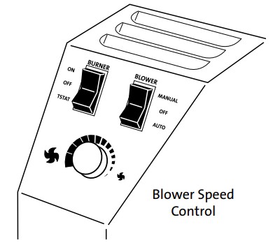 Figure 47. Blower Wiring Diagram
Optional Antique Brick Panel Kit 155375
Tools Required: Safety glasses and gloves
- Remove the Top Plate. Simply lift if up off of thestove body. It is not fastened.
- Remove the Glass Frame. Disengage the two compression latches located at the top of the firebox and lift the lass frame up and off of the stove. See Fig. 49.
- Remove the Logset. These parts are not fastened. Simply lift them out of the firebox. You do not have to emove the embers.
- Install the Rear Panel. Tilt the Rear Panel top first to slide behind the exhaust baffle and position it up against the back wall. See Fig. 50.
- Install the Side Panels. Tilt each panel, bottom edge first, into position against the side walls. The panels will stand on their own against the wall. Push them back against the Rear Panel. Fig. 51.
- Reinstall the Logset. See page 21. BE CERTAIN THAT NO EMBERS ARE BLOCKING THE PILOT ASSEMBLY OPENING.
- Replace the Glass Frame. Slide the frame down the slot in the front of the firebox. Be sure to push the frame into the slot in the bottom to ensure it is fully seated. The gasket at the top of the frame should be flush with the top of the firebox. Pull the compression latches out to engage with the top lip of the glass frame.
- Replace the Top Plate.
Figure 48. Brick Kit Contents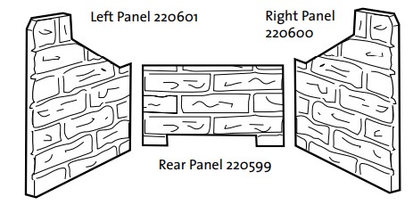 Figure 49. Release the glass frame latches.
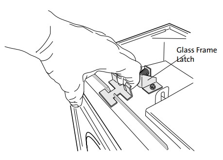 Figure 50. Install the Rear Panel to fit behind the baffle.
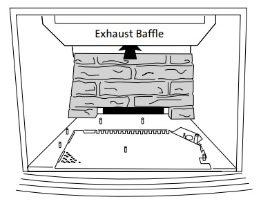 Figure 51. Install the Side Panels.
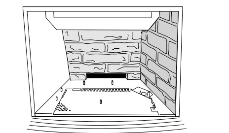
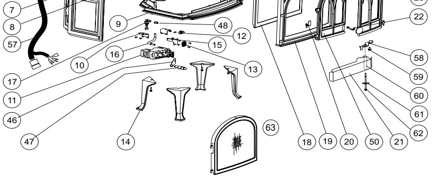
GF 400 DV Sebago Illustrated Parts Breakdown
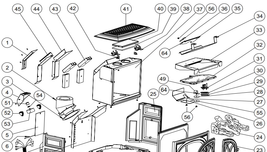
Figure 52. Illustrated Parts Breakdown – GF 400 DV MV
 GF 400 DV Sebago Parts List
| Cast Iron Parts | Matte Black Paint | Blue BlackEnamel | Ivory Enamel | Jøtul IronPaint | Jøtul IronEnamel | Brown MajolicaEnamel | Blue MajolicaEnamel |
| 7. Left Side Plate | 10391892 | 10421727 | 10421729 | 10391885 | 10421746 | 10421747 | 10421748 |
| 9. Bottom Plate | 10396392 | 10396327 | 10396329 | 10396385 | 10396346 | 10396347 | 10396348 |
| 14. Legs, (4) | 10192592 | 10192527 | 10192529 | 10192585 | 10192546 | 10192547 | 10192548 |
| 19. Front, Complete | 15565492 | 155660 | 155672 | 15565485 | 15565446 | 15565447 | 15565448 |
| After SN 33402 | 10391892 | 157722 | n/a | n/a | n/a | 157723 | na |
| 23. Right Door | 15772192 | 10421627 | 10421629 | 10421685 | 10421646 | 10421647 | 10421648 |
| 25. Right Side Plate | 10421692 | 10421827 | 10421829 | 10391985 | 10421846 | 10421847 | 10421848 |
| 41. Top Plate | 10391992 | 10396227 | 10396229 | 10396285 | 10396246 | 10396247 | 10396248 |
| 50. Left Door | 10396292 | 10421527 | 10421529 | 10421585 | 10421546 | 10421547 | 10421548 |
1. Air Divider ………………………………………………………………… 2206242. Simpson DuraVent Collar ………………………………………. 1291263. Collar Gasket ……………………………………………………………. 1291184.Switch Box ……………………………………………………………….. 2205845. Rating Plate ……………………………………………………………… 2206136. Lanyard……………………………………………………………………… 1291598. Rear Shroud ……………………………………………………………… 22055810. Valve Bracket ……………………………………………………………. 22035211. Valve – NG / 50% TD, Hi-Temp ……………………………….. 222263
Gas Valve, MV – 50% TD, SIT 821 ……………………….226560*12. Elbow, 3/8” Brass …………………………………………………….. 12912913. Terminal Block …………………………………………………………. 12915415. Bracket, Terminal Block …………………………………………… 22061416. Gas Line Kit, 5/16” x 10” w/ fittings ……………………….. 15603717. Orifice Holder Assembly ………………………………………… 12966818. Glass Frame Assembly ……………………………………………. 155398Glass Panel Replacement Kit …………………………………. 155553Glass Pane, Ceramic ………………………………………………… 220567Glass Gasket, 7/16” Tadpole ………………………………….. 129124Glass Frame …………………………………………………………. 12972592Glass Clips, (4) Replace Kit Only …………………………… 22004220. Keeper, Door Latch …………………………………………………. 22060421. Control Door ……………………………………………………………. 22118822. Door Latch ……………………………………………………………….. 22060324. Log Set ………………………………………………………………………. 15537826. Air Intake Gasket ……………………………………………………… 22064227. Air Intake Restrictor ………………………………………………… 22060228. Air Shutter Gasket …………………………………………………… 22073429. Pilot Assembly Gasket …………………………………………… 12967030. Pilot Assembly Spacer…………………………………………….. 22054631. Pilot Assembly, w/NG orifice …………………………………. 129471Pilot Orifice NG #51 …………………………………………………. 129472Pilot Orifice LP #30 …………………………………………………. 129473Jam Nut – Orifice Holder …………………………………………. 129152Ferrule (2) …………………………………………………………………. 129463Nut (2) ……………………………………………………………………….. 129464Pilot Line w/ Fitting …………………………………………………. 129446Thermocouple …………………………………………………………. 129766Electrode ………………………………………………………………….. 129765Thermopile ……………………………………………………………..309452732. Burner Assembly (SN >44002286) ………………………… 158118Burner Assembly (SN <44002287) ………………………… 15533633. Burner Skirt ( >SN 44002286) w/venturi …………….. 224956Burner Skirt ( <SN 44002287) ……………………………….. 22058234. Exhaust Baffle ………………………………………………………….. 22056535. Exhaust Restrictor …………………………………………………… 22056336. Exhaust Restrictor Gasket ………………………………………. 220583
37. Firebox Assembly ……………………………………………………. 22196038. Latch Assembly ………………………………………………………. 22009139. Relief Door Gasket ………………………………………………….. 12931940. Relief Door ……………………………………………………………….. 12964042. Relief Door Guide …………………………………………………… 12949943. Heat Fins, (4) Matte Black Paint ……………………….. 22242492Heat Fins, (4) Jøtul Iron Paint …………………………….. 2224248544. Inner Shroud, Right ………………………………………………… 22059645. Inner Shroud, Left …………………………………………………… 22059746. Ignitor Bracket ……………………………………………………….390257647. Ignitor ………………………………………………………………………390257348. Burner Orifice, NG #33 …………………………………………… 220641Burner Orifice, LP 1.65mm …………………………………… 22063849. Primary Air Shutter Tube( >SN 44002286) ………….. 224903Primary Air Shutter w/handle (<SN 44002287) ….. 22079051. Rheostat Knob …………………………………………………………. 22070952. Rocker Switch, (2) ……………………………………………………. 22070353. Rheostat …………………………………………………………………… 22097054. Retaining Collar ……………………………………………………… 22071755. Fender Washer …………………………………………………………. 11802356. Wingnut, (3) ……………………………………………………………… 11797557. Wire Harness Asy. SN > 30,000 (5-Pin Cnctr.) ………. 156034Wire Harness Asy. SN < 30,000 (4-Pin Cnctr.) ………. 15539758. Control Door Hinge ………………………………………………… 22117659. Bolt, M6 x 20 Blk Hex Hd ………………………………………… 11711760. Spacer, .375 o.d. x 3.172 …………………………………………. 11804061. Washer, Fender .250 x 1.500 dia. …………………………… 11802962. Bolt, M6x100 Hex ……………………………………………………. 11795563. Safety Screen Barrier ……………………………………………… 15771364. Air Shutter Handle >SN 44002286 ……………………….. 224954** Wire Harness Retainer ………………………………………… 220733** Screen Barrier Bracket Caps, 4 …………………………. 225474* > SN 6300000** Parts not illustrated
Accessories
Variable Speed Blower …………………………………..156000Brick Panel Kit …………………………………………………155375Universal Leg Leveler Kit ………………………………..156096Wall Thermostat ………………………………………………750003Remote Control ……………………………………………….750002Floor Bracket Kit ………………………………………………750304Fuel Conversion Kit to Propane …………………….155351Fuel Conversion Kit to Natural Gas ……………….155352
| ALWAYS USE REPLACEMENTS PARTS PROVIDED BY AN AUTHORIZED JØTUL DEALER ONLY. |
Jøtul Gas Product Warranty
This warranty policy applies to gas products identified by Jøtul, Scan, and Atra trade names, as set forth below. A. LIMITED FIVE YEAR WARRANTY – Cast Iron, Steel Doors, Surround Components, Firebox:
Jøtul North America Inc. (JØTUL) warrants, to the original retail purchaser, that those components of the Jøtul, Scan, or Atra Gas Stove or Fireplace specified above will be free of defects in material and workmanship for a period of five (5) years from the date of purchase. This warranty is subject to the terms, exclusions and limitations set forth in the following text.B. LIMITED TWO YEAR WARRANTY – Burner, Burner Treatments, Firebox Panels: JØTUL warrants, to the original retail purchaser, that those components of the Jøtul, Scan, or Atra Gas Stove or Fireplace specified above will be free of defects in material and workmanship for a period of two (2) years from the date of purchase. This warranty is subject to the terms, exclusions, and limitations set forth in the following text.
C. LIMITED TWO YEAR WARRANTY – Enamel Finish:JØTUL warrants, to the original retail purchaser, the enamel finish on cast iron components of the Jøtul Stove or Fireplace Insert specified above against peeling or fading for a period of two (2) years from the date of purchase. This warranty is subject to the terms, exclusions and limitations set forth below.D. LIMITED ONE YEAR WARRANTY – Gas & Electrical Components (controls, plumbing, valve, blower):JØTUL warrants, to the original retail purchaser, that those components of the Jøtul, Scan, or Atra Gas Stove or Fireplace specified above will be free of defects in material and workmanship for a period of one (1) year from the date of purchase. This warranty is subject to the terms, exclusions, and limitations set forth in the following text.
JØTUL will repair or replace (including parts & labor), at its option, any of the above components determined by JØTUL to be covered by this warranty. You must, at your own expense, arrange to deliver or ship the component to an authorized Jøtul, Scan, or Atra dealer and arrange for pickup or delivery of the component after repairs have been made. If, upon inspection, JØTUL determines that the component is covered by this warranty, the repair or replacement will be made as set forth above. This warranty is not transferable and is extended only to, and is solely for the benefit of, the original retail purchaser of the Jøtul, Scan, or Atra Gas Stove or Fireplace. This paragraph sets forth the sole remedy available under this warranty in the event of any defect in the Jøtul, Scan, or Atra Gas Stove or Fireplace. The warranty period for any replaced component will be the remaining unexpired portion of the warranty period for the original component. Please retain your dated sales receipt in your records as proof of purchase.
EXCLUSIONS AND LIMITATIONSNOTICE: This warranty is void if installation or service is performed by someone other than an authorized installer, service agency or gas supplier, or if installation is not in conformance with the installation and operating instructions contained in this owner’s manual or local and/ or national fire and building regulations. A listing of local authorized installers, service agencies and gas suppliers can be obtained from the National Fireplace Institute at http://www.nficertified.org/.This warranty does not cover the following:
- Repair or replacement of parts that are subject to normal wear and tear during the warranty period or to parts that may require replacement in connection with normal maintenance. These parts include gaskets and glass (except to the extent such parts suffer damage from thermal stress).
- Damage due to incorrect installations not in conformance with the installation instructions contained in this owner’s manual or local and/or national fire and building regulations.
- Damage due to service performed by an installer, service agency or gas supplier unless otherwise agreed to in writing by JØTUL.
- Labor or other costs associated with the repair of gas controls, plumbing, burners, log set, or sheet metal firebox beyond the warranty period.
- Damage caused by unauthorized modification, use or repair.
- Damage to enameled surfaces caused by improper operation or misuse, including use that is not in conformance with the operating instructions contained in this owner’s manual. Such damage can typically be identified by bubbling, cracking, or discoloration of the enamel finish.
- Costs incurred by travel time and/or loss of service.
- Damage incurred while the Jøtul, Scan, or Atra Gas Stove or Fireplace is in transit.
IN NO EVENT SHALL JØTUL, ITS PARENT COMPANY, SHAREHOLDERS, AFFILIATES, OFFICERS, EMPLOYEES, AGENTS OR REPRESENTATIVES BE LIABLE OR RESPONSIBLE TO YOU FOR ANY SPECIAL, INDIRECT, INCIDENTAL, CONSEQUENTIAL, PUNITIVE OR OTHER SIMILAR DAMAGES, INCLUDING, BUT NOT LIMITED TO, LOST PROFITS, LOST SALES, INJURY TO PERSON OR PROPERTY, OR DAMAGES TO A STRUCTURE OR ITS CONTENTS, ARISINGUNDER ANY THEORY OF LAW WHATSOEVER. ALL IMPLIED WARRANTIES, INCLUDING THE IMPLIED WARRANTIES OF MERCHANTABILITY AND FITNESS FOR A PARTICULAR PURPOSE, OR OTHERWISE, ARE LIMITED IN DURATION TO THE LENGTH OF THIS WRITTEN WARRANTY. EXCEPT AS EXPRESSLY SET FORTH HEREIN, JØTUL MAKES NO ORAL, WRITTEN OR OTHER WARRANTY WITH RESPECT TO JØTUL, SCAN OR ATRA GAS STOVES OR FIREPLACES.
Some states do not allow the exclusion or limitation of incidental or consequential damages, or limitations on the length of implied warranties. Therefore, the above exclusions or limitations may not apply to you. This warranty gives you specific legal rights, and you may have other rights, which vary from state to state.JØTUL reserves the right to discontinue, modify or change the materials used to produce the Jøtul, Scan, or Atra Gas Stove or Fireplace. JØTUL shall have the right to replace any defective component with substitute components determined by JØTUL to be of substantially equal quality and price.The dollar value of JØTUL’s liability for breach of this warranty shall be limited exclusively to the cost of furnishing a replacement component. JØTUL shall not, in any event, be liable for the cost of labor expended by others in connection with any defective component. Any costs or expenses beyond those expressly assumed by JØTUL under the terms of this warranty shall be the sole responsibility of the owner(s) of the Jøtul, Scan, or Atra Gas Stove or Fireplace.
No dealer, distributor, or other person is authorized to modify, augment, or extend this limited warranty on behalf of JØTUL. NO MODIFICATION OR CHANGE TO THIS WARRANTY WILL BE EFFECTIVE UNLESS IT IS MADE IN A WRITTEN DOCUMENT MANUALLY SIGNED BY AN AUTHORIZED OFFICER OF JØTUL.An authorized installer may have been provided with certain information related particularly to the Jøtul, Scan, or Atra Gas Stove or Fireplace; however, no authorized installer or another person who may service the appliance is an agent of JØTUL. No inference should be made that JØTUL has tested, certified, or otherwise pronounced any person as qualified to install or service the appliance. JØTUL shall not be liable or otherwise responsible for any error or omission by a person installing or servicing a Jøtul, Scan, or Atra Gas Stove or Fireplace. If you believe your Jøtul, Scan, or Atra Gas Stove or Fireplace is defective, you should contact your nearest authorized Jøtul, Scan, or Atra dealer, who will process a warranty claim. IN ORDER TO QUALIFY FOR WARRANTY COVERAGE, JØTUL MUST RECEIVE NOTICE OF A POSSIBLE DEFECT WITHIN SIXTY (60) DAYS OF THE DATE THE DEFECT IS FIRST DISCOVERED, OR REASONABLY COULD HAVE BEEN DISCOVERED. This warranty is given by Jøtul North America, Inc., 55 Hutcherson Drive, Gorham, Maine 04038 USA
LIGHTING INSTRUCTIONS
FOR YOUR SAFETY, READ BEFORE LIGHTING.
WARNING:IF YOU DO NOT FOLLOW THESE INSTRUCTIONS EXACTLY, A FIRE OR EXPLOSION MAY RESULT CAUSING PROPERTY DAMAGE, PERSONAL INJURY, OR LOSS OF LIFE.
A. This appliance has a pilot which must be lit by hand. When lighting the pilot, follow these instructions exactly.B. BEFORE LIGHTING, smell all around the appliance area for as. Be sure to smell next to the floor because some gas is heavier than air and will settle to the floor.WHAT TO DO IF YOU SMELL GAS:
- Extinguish any open flame.
- Open windows.
- Do not light any appliance.
- Do not touch any electrical switches.
- Do not use any phone in your building.
- Immediately call your gas supplier from a neighbor’s phone.
- If your gas supplier cannot be reached, call the fire department.
C. Use only your hand to push in or turn the gascontrol knob. Never use tools. If the knob will not push in or turn by hand, do not try to repair it. Call a qualified technician. Force or attempted repair may result in a fire or explosion.
D. Do not use this appliance if any part has been underwater. Immediately call a qualified service technician to inspect the appliance and to replace any part of the control system and any gas control which has been underwater.
LIGHTING INSTRUCTIONS
- STOP! Read the safety information above.
- Set the BURNER ON/OFF switch to “OFF”, or set the thermostat to the lowest setting (if used).
- Confirm that the gas supply line shut-off valve is open.
- Push in Valve Control knob slightly and turn clockwise to “OFF”.NOTE: Knob cannot be turned from “PILOT” to “OFF” unless the knob is pushed in slightly. Do not force.
- Wait five (5) minutes to clear out any gas. If you then smell gas, STOP! Follow “B” in the safety information above on this page. If you do not smell gas, go to the next step.
- Push in Valve Control knob slightly and turn counter-clockwise to “PILOT”. Pilot Assembly
- Push in the control knob all the way and hold in. Immediately light the pilot by triggering the spark ignitor (push the red button repeatedly) until the pilot lights. Continue to hold the control knob in for about one minute after the pilot lights. Release the knob and it should spring back. The pilot should remain lit. If it goes out, repeat Steps 5 through 8.• If the knob does not return when released, stop and immediately call your service technician or gas supplier.• If the pilot will not stay lit after several tries, turn the control knob to OFF and call your servicetechnician or gas supplier.
- Turn Valve Control knob counter-clockwise to “ON”.
- Set the BURNER switch to “ON”, or set the thermostat (if used) to the desired temperature.


TO TURN OFF GAS TO THE APPLIANCE:
1. Place BURNER switch in” OFF” position. The pilot will remain lit for normal service.2. For complete shutdown, depress the Valve Control Knob and turn clockwise![]() to “OFF”. Do not force.
to “OFF”. Do not force.
This appliance must be installed in conformance with local and national building regulations. Before beginning the installation, it is important that these instructions be carefully read and understood. Jøtul maintains a policy of continual product development. Consequently, products may differ in specification, color or type of accessories from those illustrated or described in various publications.
Jøtul ASP.O. Box 1411N-1602 FredrikstadNorwayJøtul North America55 Hutcherson Dr.Gorham, ME 04038-2634
References
[xyz-ips snippet=”download-snippet”]