 #8301 V3 & #8302 V3 MANUAL
Total Length…………………………….730mm(28.7in)Beam……………………………………….180mm(7.1in)Speed………………………………………………60+KPH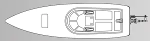
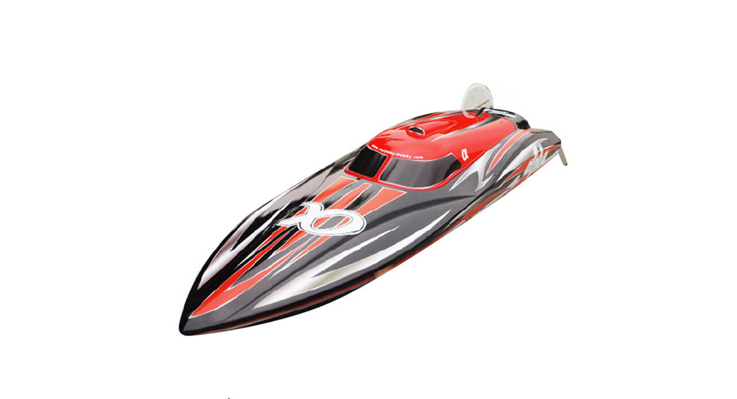
Model No: 8301 Bullet V3 Deep Vee
Total Length……………………………730mm(28.7in)Beam……………………………………..209mm(8.23in)Speed……………………………………………..60+KPH
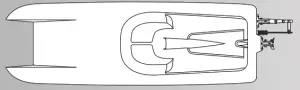
Model No: 8302 US . 1 V3 Catamaran
Universal Assembly
Motor…………………………………………………………….Water-cooled 2815 out-runer brushless motor(included)Radio System………………………………………………………2.4G 2CH Digital Proportional Transmitter(Included)Speed Control…………………………………………………….Water cooling 60A Brushless ESC w/BEC (Included)Drive System………………………………………………………………………………………. 4mm Flex Cable Direct DrivePropeller……………………………………………………………………………………………….Three Blade Metal PropellerBattery………………………………………………………Two packs of 7.4V 4000mAh 35C LiPo Pack(Not Included)
Caution for LiPo battery:ESC with low voltage hard cut off at 3.2V per cell, when driving your boat, as soon as you notice boat stop, that means ESC low voltage cut off effective, you should immediately drive the boat back to shore at slow speed, recharge battery, and race again. don’t keep racing boat when ESC low voltage cut off effective, otherwise, you will allow battery over-discharge, the battery voltage will reach very low and won’t be recharged again.
IMPORTANT: THESE MODELS ARE CAPABLE OF OVER 60 KPH, PERSONAL INJURY OR PROPERTY DAMAGE MAY RESULT FROM MISUSE OF THESE PRODUCTS, TAKE CARE AND ENJOY OUR MODEL RESPONSIBLY.
Introduction
Thank you for purchasing the Joysway brushless motorboat! This manual contains the instructions you need to safely prepare, operate, and maintain your R/C boat. Read over this manual thoroughly before operating the Joysway brushless motorboat.
Safety Precautions
- Operating care to avoid touching the propeller anytime the motor is operating. If your fingers, hands, etc. come in contact with the spinning propeller, you may be severely injured. This model is capable of inflicting property damage and severe personal injury if a collision occurs. Racing your boat responsibly, stay clear of people, full-scale boats, and wildlife.
- The metal hardware on your boat can be sharp. Be careful handling the parts.
- The brushless motor may become hot. After a run allows the motor to cool before touching it.
Specifications a Description Changes
All pictures, descriptions, and specifications found in this instruction manual are subject to change without notice. Joysway maintains no responsibility for inadvertent errors in this manual.
( Items Required For Completion a Battery Pack Recommendations )
You will need to purchase the following items to operate your Joysway brushless motorboat. We highly recommend the use of the following products.Battery Recommendation7.4V 4000mAh 35C Lipo battery pack (need 2 packs, series connection)NOTE If you have existing7.4 V Lipo battery packs, you can update them for use by changing the connectors to EC4 connectors which are included in the kits bag, be sure to solder the connectors to the battens in the proper polarity. (2 EC4 connectors are already soldered with the ESC, the other 2 EC4 connectors are included in the kits bag)
Charter Recommendation
2S/3S Balance Charger and adapter, or multi-functional intelligent charger.NOTE: You will also need 4 “AA” alkaline batteries for the transmitter.
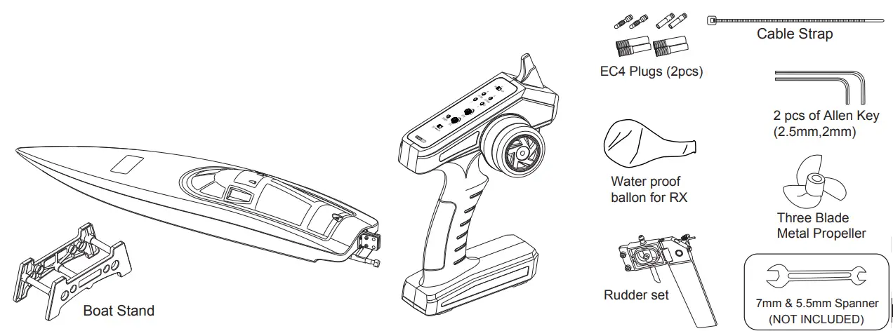
Contents Of SET
- Water-cooled 2815 out-runer brushless motor(included) (Pre-installed)
- 60A Water cooling Brushless ESC w/BEC(Pre-installed)
- Powerful Steering 37g Servo (Pre-installed)
- 2.4GHz 2CH Pistol Transmitter
- Display Boat Standkits bag contents
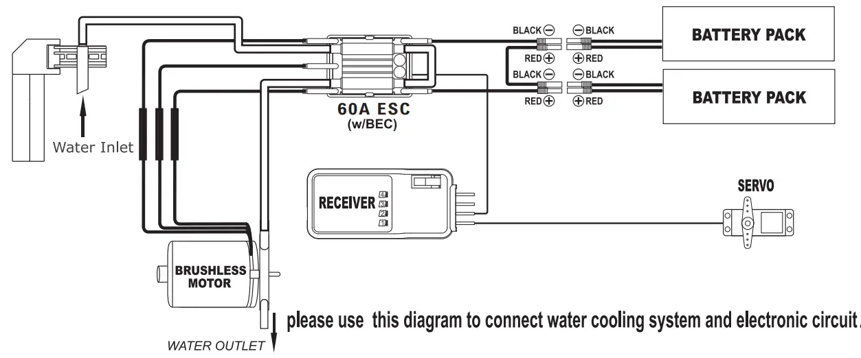
CIRCUIT AND COOLING SYSTEM DIAGRAM IN THE BOAT
Preparing Your Boat For Operation
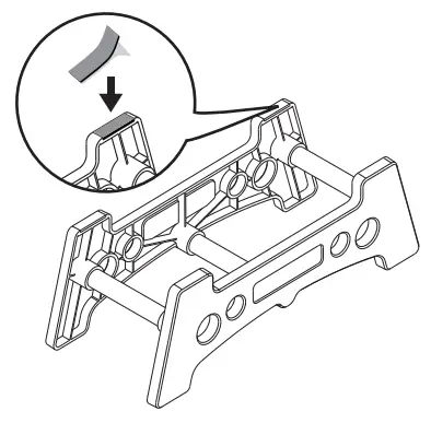
Assembling the boat standInsert three ABS pipes into the holes of two boat stands shown as photos, compress boat stands and ABS pipes tightly, then stick EVA to the four angles, this will protect the hull bottom from scratches during construction and storage.NOTE: Bullet deep vee and US.1 catamaran boat use the same boat stand.
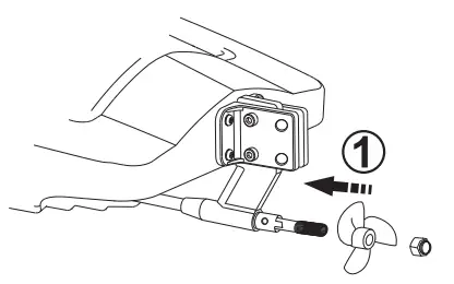
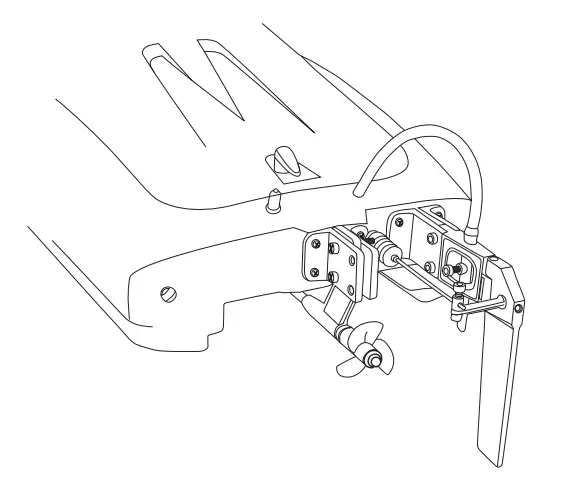
Installing the rudder and propellerConcerning package safety, the rudder and propeller are not pre-installed. They are packed well in the kit’s bag. Follow the below steps to install them by yourself easily
1. Loosen the screw on the propeller shaft by 7mm Spanner, put the propeller in then retighten the screw.
2. Insert the rudder support into the support which is already installed on the rear of the hull. Thread the two pcs of M3 screw in, Apply two pcs of M3 ut on the screws, retighten the screws and nuts by 2.5mm Allen Key and 5.5mm Spanner.
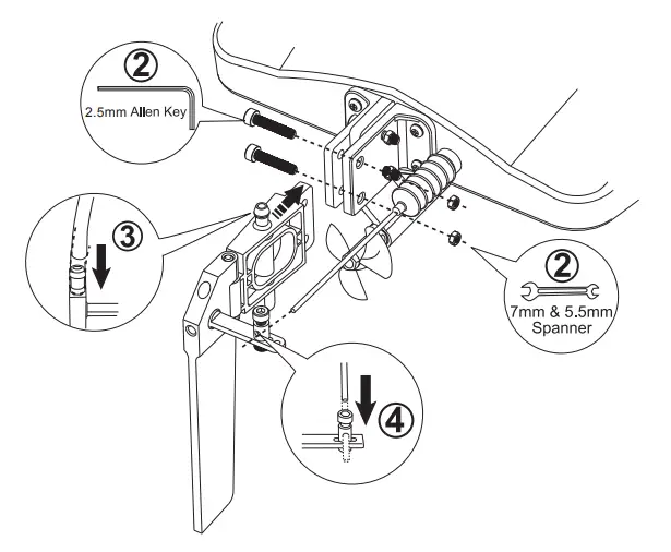
3. Thread the silicone tube in the brass water inlet.4. Loosen the adjuster on the servo horn so as to push the rudder rod to thread in the adjuster located in the rudder horn. Make sure the rudder entered and then Retighten the two adjusters with a 2.5mm Allen Key.
Rudder Assembly For US.1 Catamaran
 NOTE: Please install rudder and support on the right support which is pre-installed on the rear of the hull in the factory. Installing rudder and support on the right side is effective for good performance and stability.
Installing the transmitter
NOTE: The transmitter is not water-resistant and should never come in contact with water.
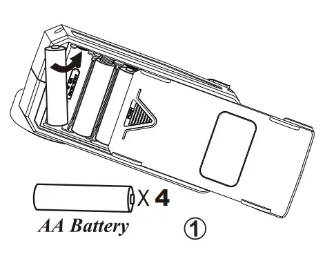
- Install four fresh “AA” batteries. Follow the diagram located at the bottom of the battery tray for proper battery orientation.

- Turn the transmitter “ON” The battery light should glow bright RED.
Receiver connection diagram
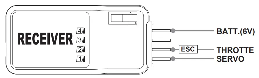
Note: If ESC with BEC function, no need to connect the battery with the receiver.
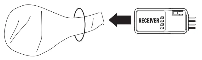
Caution: Before racing the boat, Please use the ballon supplied in the tool, bag to wrap the receiver for waterproof
Installing the Battery
NOTE: We recommend you 2 packs of 7.4V 4000mAh 35C Lipo battery for maximum performance. Using the Provided Hook and Loop which are already tied on the battery locators inside the hull to tie the battery. The battery locators help align the batteries for the best running center of gravity for maximum performance. Blowing is the battery’s location inside the hull.

NOTE: 1. There is a waterproof rubber ring placed along with the slot of the hull, always make sure it’s secured positioned before re-position the upper deck.
TRANSMITTER/RECEIVER BINDING
The binding process effectively ties the transmitter and receiver together. Under normal circumstances, both items are supplied like this from the factory. If, however, you find that your transmitter and receiver are not bound(receiver’s red LED is on), you should do the following:
1) Switch “ON” the transmitter.2) Switch “ON” the receiver by connecting the battery to ESC, and the ESC cord is plugged into the Receiver properly(Note: ESC has BEC function).
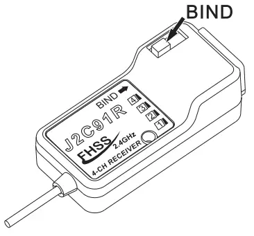
3) Press down the “BIND” button on the receiver, the receiver’s green LED will be on to indicate that binding has been successful and the receiver will now accept commands from the transmitter.
Note 1: During the binding process, the transmitter and receiver should be no more than one meter apart and no other similar devices should be within 10 meters.Note 2: if the green light flashing, showing the binding failure, please do it again as per the above indication.
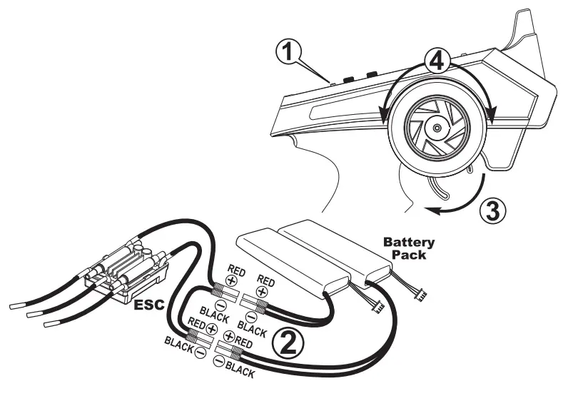
Checking the radio system
- Always turn the power “ON” to the transmitter before connecting the batteries with the ESC.
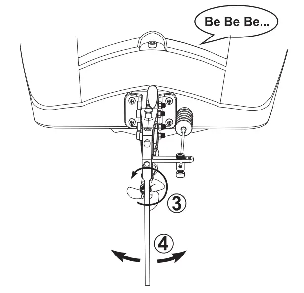
- Plug the battery into the ESC plugs and listen for three continuous >Be<>Be<>Be<. (Signal noise of auto-detected ESC)
- Pull the throttle & motor rotate in an anticlockwise direction, your motor is now armed and ready for operation.
- Check the direction of the rudder, the trailing edge of the rudder should turn right when the right input is given. Conversely, when left input is given, the trailing edge of the rudder should turn left.
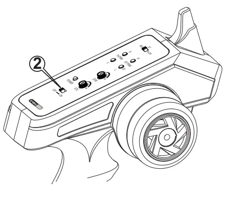
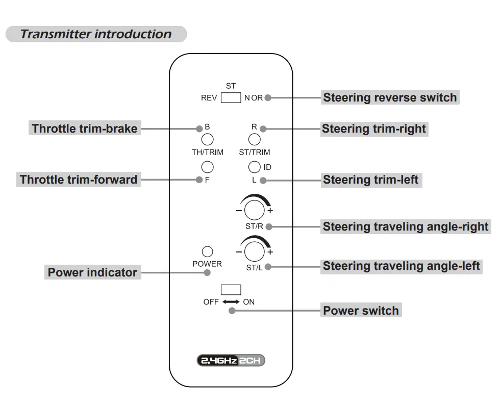 EPA Adjustment
FunctionUse this when performing left and right steering angle adjustments. End Point Adjustment (EPA) adjusting value range: 0%-100%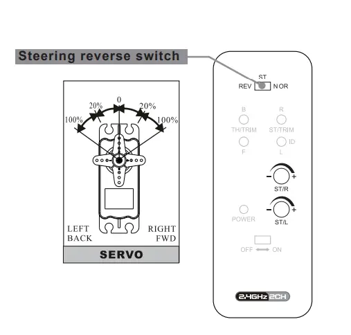 Setting
- Steering (right side) angle adjustment Rotate “ST/R” knob to the left endpoint means minimum value 0%, right endpoint means maximum value 100%.
- Steering (left side) angle adjustment Rotate “ST/L” knob to the left endpoint means minimum value 0%, right endpoint means maximum value 100%.
CAUTION:When adjusting this function, make sure the direction is in agreement with the boat direction, you can adjust by the STEERING “REV-NOR” button.
Trim Adjustment
Steering trimAdjust “ST/TRIM” “R/L” so that rudder is centered prior to operation, you may adjust this control to make the boat run straight during operation.
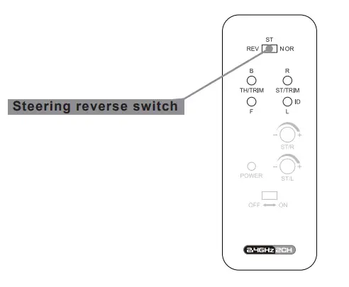 CAUTION:When adjusting steering trim, make sure the direction is in agreement with the boat direction, you can adjust by the STEERING “REV-NOR” button.Throttle trimAdjust “TH/TRIM” “B/F” to stop the propeller from turning while the throttle trigger is in the neutral position.
Speed Control Specification
The Joysway brushless motorboat is assembled with 60A water-cooled brushless ESC, please see blowing the specification:protections: Thermo protection activated at 120°C. LVP(low voltage protection) engaged when Lipo battery (per cell) drop down to 3.2 Voltage.Operating Cells: 2S – 4S LipoCurrent Rating: 60APeak Current: 70A within 10 seconds.BEC Output: 2A / 5VCalibration:
- Ser the trigger to maximum throttle then turn on the transmitter.
- Connect the motor and receiver to the ESC.
- After 4 high-pitched tones, set the trigger to minimum throttle.
- After 3 repeat monotones, cut off the power of ESC.
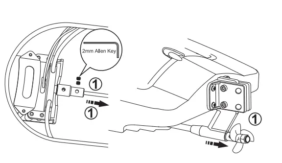
Lubricating The Drive Shaft
Lubricating the flex shaft is vital to the life of the drivetrain. The lubricant also acts as a water seal, keeping water from entering the hull through the stuffing box.Lubricate the flex shaft, propeller shaft, and all moving parts after every 2-3 hours of operation.
- Use the 2mm Allen key to lose the two grub screws of the coupler which connects the flex shaft, then slide the flex shaft w/ prop shaft out of the stuffing tube.
- Lubricate the flex shaft w/ prop shaft with the waterproof marine grease, reinstall the flex shaft w/ prop shaft in reverse order, be sure to retighten the two grub screws of the coupler.
NOTE: Running the model boat in saltwater could cause some parts to corrode. If you run the boat in salt water, rinse it thoroughly in freshwater after each use and lubricate the drive system.
Spare part list
To order Joysway brushless motorboat spare parts, use the part numbers in the spare parts list that follows.
|
PART NO. |
DESCRIPTION |
| 83002 | waterproof rubber ring (PK2) for Bullet |
| 83004 | waterproof rubber ring (PK2) for the USA |
| 83013 | Aluminum alloy rudder assembly set |
| 83014 | 37g standard servo |
| 83016 | rudder clevis (PK2) |
| 83018 | rudder assembly plastic bracket set |
| 830103 | Bullet hull only, without decals |
| 920101 | 7.4V 4000mAh 35C LiPo Pack |
| 92025 | P1.4X37mm Three Blade metal Propeller-V2&V3 |
| 920102 | 60A Brushless ESC w/ two EC4 connector-V2&V3 |
| 93017 | water-proof rudder pushing rod tube(PK2) |
| 930518 | J2C93 2.4GHz 2CH Transmitter |
| 930519 | J2C91R 2.4GHz 4CH Receiver |
| 830105 | water cooling mount of BL2815 motor-V2&V3 |
| 830107 | BL2815 Out-runner brushless motor-V2&V3 |
| 830108 | Coupler(4mm) of BL2815 motor-V2&V3 |
| 830109 | 4mm Flex shaft set for Bullet-V2&V3 |
| 830110 | rear shaft strut support set 4mm version-V2&V3 |
| 830111 | Connected rod of Rudder for Bullet-V2&V3 |
| 830202 | 4mm Flex shaft set for US.1-V2&V3 |
| 830203 | Connected rod of Rudder for US.1-V2&V3 |
| 860210 | 2S/3S balance charger with DC adapter |
| 860211 | 2S/3S balance charger with AC Europe wall adapter |
 report this ad
![]()
FCC REQUIREMENT![]() This device complies with Part 15 of the FCC Rules. Operation is subject to the following two conditions: (1) This device may not cause harmful interference, and (2) This device must accept any interference received, including interference that may cause undesired operation. CAUTION: Changes or modifications to this product not expressly approved by the party responsible for compliance may void the user’s authority to operate the equipment.
This device complies with Part 15 of the FCC Rules. Operation is subject to the following two conditions: (1) This device may not cause harmful interference, and (2) This device must accept any interference received, including interference that may cause undesired operation. CAUTION: Changes or modifications to this product not expressly approved by the party responsible for compliance may void the user’s authority to operate the equipment.
[xyz-ips snippet=”download-snippet”]