Kanex Double Gang. 2×1 HDMI USB 2.0 Wall Plate Switcher over HDBaseT PoH User Guide
SAFETY PRECAUTIONS
To ensure the best performance from the product, please read all instructions carefully before using the device. Save this manual for further reference
- Unpack the equipment carefully and save the original box and packing material for possible future shipment
- Follow basic safety precautions to reduce the risk of fire, electrical shock and injury to persons
- Do not dismantle the housing or modify the module. It may result in electrical shock or burn
- Using supplies or parts not meeting the products’ specifications may cause damage, deterioration or malfunction
- Refer all servicing to qualified service personnel
- To prevent fire or shock hazard, do not expose the unit to rain, moisture or install this product near water
- Do not put any heavy items on the extension cable in case of extrusion
- Do not remove the housing of the device as opening or removing housing may expose you to dangerous voltage or other hazard
- Install the device in a place with fine ventilation to avoid damage caused by overheat.
- Keep the module away from liquids
- Spillage into the housing may result in fire, electrical shock, or equipment damage. If an object or liquid falls or spills on to the housing, unplug the module immediately
- Do not twist or pull by force ends of the optical cable. It can cause malfunction
- Do not use liquid or aerosol cleaners to clean this unit. Always unplug the power to the device before cleaning
- Unplug the power cord when left unused for a long period of time
- Information on disposal for scrapped devices: do not burn or mix with general household waste, please treat them as normal electrical wastes.
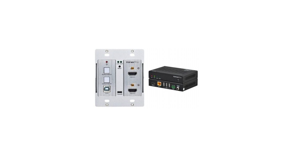
1. Product Introduction
The KanexPro EXT-HDBTKVM3 is a US Decora style double-gang, 2×1 HDMI wall plate transmitter and receiver set designed to switch two HDMI inputs with one USB 2.0 input to a remote display or a projector up to 131ft.(40m) at 4K/60 and 330ft.(100m) at 1080p/60 video and audio over single cat5e/6/7 cable. The outputs are via HDBaseT port
Easy to Control and Switch Inputs
The wall plate transmitter can be easily controlled by selecting the “Source /Auto” button on the front panel. By holding the button for 3 seconds, it will go under auto switching mode and will auto-detect HDMI inputs when connected. It also supports CEC, which can turn the DISPLAY ON/OFF right from the button on front panel for the far-end display device, and it can be programmed by IR learning or RS232 command to ensure the compatibility with various display devices.Receiver Inclusive with two USB 2.0 ports and KVM support
The EXT-HDBTKVM3 includes the end point for connecting it over ethernet to the receiver, which then connects to the 4K display. The receiver has multiport USB 2.0 which can be used as a KVM or for VTC applications.PoH A Safe and Regulated Power for Sustainability
The output from the wall plate is via HDBaseT port. The receiver powers the wall plate remotely. Power over HDBaseT (PoH) offers voltage protection when sent over ethernet without burning the other side of devices or receivers. Our wall plate kit comes with only one power supply, which means that, it can be powered from the receiver side saving installers time and added cost to installing a power outlet.
Applications:
USB for Conferencing in AV & Digital Signage
Perfect for conference rooms, boardrooms and digital signage applications where the extender offers two USB 2.0 ports allowing touch-panel screens, cameras, USB Mic and SOFTCODEC systems to be used for video conferencing or KVM functionality.1.1 Features
- US Decora Style Dual Gang 2 X HDMI wall plate & USB 2
- Extend USB 2.0, 4K UHD video and audio up to 100 meters over HDBase
- Automatically detects active input when source is connected
- Driverless USB 2.0 for webcam video emulation and AEC speakerphone audio
- USB 2.0 also supports touch-screen functionality and keyboard-video- mouse (KVM)
- Distribute & 60Hz signals up to 4:2:0
- Supports standard 1080p & WUXGA resolutions
- HDCP 2.2 compliant
- Supports bi-directional RS232 pass-through w/ HDBaseT connection
- CEC to turn on/off display by the DISPLAY ON/OFF button
- Bi-directional power via PoH from Tx to Rx or vice versa
- Firmware upgrade via Micro-USB port
1.2 Package List
|
Wall plate transmitter |
l 1x Wall plate Transmitter
l 4x Mounting Screws l 1x 2-pin Terminal Block l 1x 3-pin Terminal Block |
|
Receiver |
l 1x 100m Receiver
l 2x Mounting Ears l 4x Mounting Screws l 4x Plastic Cushions l 1x RS232 Cable (3-pin to DB9) l 1x Power Adaptor (24V DC 1.25A) |
| l 1 x User Manual |
Note: Please contact your distributor or KanexPro immediately at[email protected] if any damage or defect in the components is found.Receiver
2. Specification
2.1 Transmitter
| Input | |
| Input | (2) HDMI |
| Input Connector | (2) Type-A female HDMI |
| Output | |
| Output | (1) HDBT, (1) TO PC, (1) DC OUT |
| Output Connector | (1) RJ45, (1) Type-B USB, (1) 2-pin terminal block |
| Control | |
| Control Port | (1) FIRMWARE, (1) RS232 |
| Control Connector | (1) Micro-USB, (1) 3-pin terminal block |
| General | |
| Bandwidth | 10.2Gbps |
| HDMI Version | 1.4 |
| HDCP Version | 2.2 |
| Video Resolution | Up to 4K× 4:2:0 |
| Transmission Mode | HDBaseT |
| Transmission Distance | 1080P/ ≤ 328ft/100m |
| Power Supply | Powered from the receiver by CATx cable. |
| Operation Temperature | -10℃ ~ +55℃ |
| Storage Temperature | -25℃ ~ +70℃ |
| Relative Humility | 10%-90% |
| Dimensions (W*H*D) | 3.5” x 4.0” x 1.7” |
| Net Weight | 0.55 lbs. (250g) |
2.2 Receiver
| Input | |
| Input | (1) HDBT, (3) USB |
| Input Connector | (1) RJ45, (3) Type-A USB |
| Output | |
| Output | (1) HDMI |
| Output Connector | (1) Type-A female HDMI |
| Control | |
| Control port | (1) FIRMWARE, (1) RS232 |
| Control Connector | (1) Micro-USB, (1) 3-pin terminal block |
| General | |
| Bandwidth | 10.2Gbps |
| HDMI Version | 1.4 |
| HDCP Version | 2.2 |
| Video Resolution | Up to 4K× 4:2:0 |
| Transmission Mode | HDBaseT |
| Transmission Distance | 1080P/ ≤ 328ft/100m |
| AC Adapter Input Power | 100V~240V AC, 50/60Hz |
| Input Power | 24V DC 1.25A |
| Power Consumption | 23W (Max, work with the transmitter) |
| Operation Temperature | -10℃ ~ +55℃ |
| Storage Temperature | -25℃ ~ +70℃ |
| Relative Humility | 10%-90% |
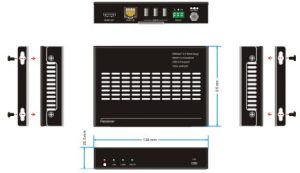
| Dimension (W*H*D) | 136mm x 25.5mm x 95mm |
| Net Weight | 365g |
Input Input Input Connector Output Output Output Connector Control Control port Control Connector General Bandwidth HDMI Version HDCP Version Video Resolution Transmission Mode Transmission Distance AC Adapter Input Power Input Power Power Consumption Operation Temperature Storage Temperature Relative Humility Dimension (W*H*D) Net Weight
3. Panel Description
3.1 Transmitter Front Panel
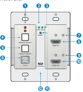
- POWER LED: The LED illuminates red when power is applied.
- LIN LED: The LED illuminates green when the transmitter is successfully connected to the receiver are by a CATx cable.
- HDCP LED:
- The LED illuminates green when the HDMI signal is transmitted with HDCP
- The LED blinks green when the HDMI signal is transmitted without HDCP.
- The LED turns off when there is no HDMI signal input.
- SOURCE SELECT: Press the button to select the next input source, or press and hold it at least 3 seconds to enable auto-switching mode. For more details, please refer to the 5.1 Signal Switching on the page 10.
- DISPLAY ON/OFF: Press the button to turn on/off the display. For more details, please refer to the 5.2 Display Control on the page 10.
- TO PC: Type-B USB port to connect a PC or other device needs to be controlled.
- HDMI IN 1 LED: The LED illuminates orange when the HDMI IN 1 port is connected to a source device, and it will turn green once the device is selected as 4K/60 2×1 Wall Plate Switcher & Extender Set input source
- HDMI IN 1: Type-A HDMI port to connect a HDMI source
- HDMI IN 2 LED: The LED illuminates orange when the HDMI IN 2 port is connected to a source device, and it will turn green once the device is selected as input source
- HDMI IN 2: Type-A HDMI port to connect a HDMI source
- RESET: Press the recessed button to reboot this unit
- FIRMWARE: Micro-USB port for firmware upgrad
3.2 Transmitter Rear Panel
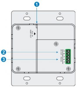
- HDBT OUT (PoC IN): RJ45 HDBaseT output port to connect to the HDBT IN port of the receiver by a CATx cable. It supports 24V PoC to enable the transmitter can be powered from receiver.
- DC OUT: 2-pin terminal block to connect a compatible device which needs to be powered. 4K/60 2×1 Wall Plate Switcher & Extender Set
- RS232: 3-pin terminal block to connect a control device (such as PC) to send RS232 command to control this unit, or to connect a third party device which needs to be controlled by RS232 pass-through. For more details, please refer to the 6. RS232 Control on the page 11.
3.3 Receiver Front Panel
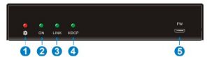
- POWER LED: The LED illuminates red when power is applied
- ON LED: The LED blinks green when the receiver is in the working status.
- LINK: The LED illuminates green when the receiver is successfully connected to the transmitter are by a CATx cable
- HDCP LED:
- The LED illuminates green when the HDMI signal is transmitted with HDCP
- The LED blinks green when the HDMI signal is transmitted without HDCP
- The LED turns off when there is no HDMI signal input
- FW: Micro-USB port for firmware upgrade
3.4 Receiver Rear Panel
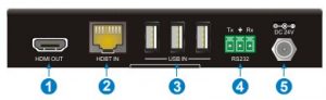
- HDMI OUT: Type-A HDMI port to connect a display
- HDBT IN: RJ45 HDBaseT input port to connect to the HDBT OUT port on the transmitter by a CATx cable.
- USB IN: Three type-A USB ports to connect HID devices (e.g. mouse, keypad and so on) to control the device which is connected to the TO PC port of the transmitter
- RS232: 3-pin terminal block to connect a control device (such as PC), or to connect a third party device which needs to be controlled by RS232 pass-through. For more details, please refer to the 6. RS232 Control on the page 11
- DC 24V: Power port to connect the 24V DC power adaptor.
4. System Connection
4.1 Usage Precaution
- Make sure all components and accessories included before installatio
- System should be installed in a clean environment with proper temperature and humidity
- All of the power switches, plugs, sockets, and power cords should be insulated and safe.
- All devices should be connected before power on.
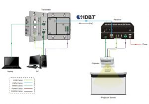
4.2 System Diagram
The following diagram illustrates typical input and output connection that can be utilized with the extender:
5.1 Signal Switching
- Press the SOURCE SELECT button to switch to next source device, and then the corresponding input LED will turn green.
- Press and hold the SOURCE SELECT button at least 3 seconds to enable autoswitching mode, and it abides by the following principles
- New input: Once a new input signal detected, the transmitter will automatically switch to this new signal.
- Signal removing Once removing the current display signal, the transmitter will automatically switch to another active HDMI input.
- Rebooting device The transmitter can save the last configuration before losing power. If the last switching mode is auto-switching, the transmitter will automatically enter autoswitching mode once rebooted, then detect all inputs and memorize their connection status for future rebooting using. If the last selected input source is still available, the transmitter will switch to this input. Otherwise, it will switch to the first available active input source starting at HDMI IN 1.
- Exit auto-switching mode The input source would remain the same when press and hold the SOURCE SELECT button again to exit the auto mode.
5.2 Display Control 1)
- Press the DISPLAY ON/OFF button to turn on/off the display.
- The DISPLAY ON/OFF can be customized by sending RS232 commands for compatibility with various displays. For more details, please refer to the 6.3.4 Button Control User-defined on the page 16.
6. RS232 Control
6.1 RS232 Connection
According the RS232 control mode, there are three types of RS232 connection for different application.
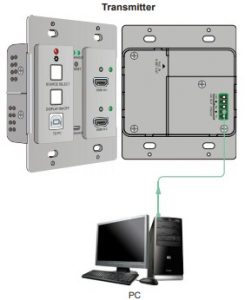
- When only control the local transmitter, please connect a control device (e.g. PC) to the RS232 port of the transmitter, the connection diagram shown as below:
2. When control the far-end third party device from local control device (e.g. PC), please connect the PC to the RS232 port of the transmitter, and then please connect the third party device (e.g. projector) to the RS232 port of receiver. The connection diagram shown as below:

3.When control the local third party device from far-end control device (e.g. PC), please connect the PC to the RS232 port of the receiver, and then please connect the third party device to the RS232 port of transmitter. The connection diagram shown as below:

6.2 RS232 Control Software
After set all needed input and output devices according to the RS232 connection diagram, please install the RS232 control software into the control PC to send RS232 command
- Installation: Copy the control software file to the control PC
- Uninstallation: Delete all the control software files in corresponding file path. Here take the software CommWatch.exe as an example. First, please double-click the following icon:

Then, the interface of the control software is showed as below
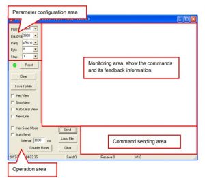
Please set the parameters of COM number, bound rate, data bit, stop bit and the parity bit correctly, then the RS232 commands can be sent in the Command Sending Area. Baud rate: 2400, 4800, 9600, 19200, 38400, 57600 or 115200. Data bit: 8. Stop bit: 1. Parity bit: none.
6.3 RS232 CommandBeside the button control on the front panel, the transmitter can be controlled by sending the below commands. Baud rate: 9600. Data bit: 8. Stop bit: 1. Parity bit: none.
6.3.1 Signal Switching
| Command | Function | Feedback Example |
| 50701% | Switch to HDMI IN 1 input. | SWITCH TO HDMI1 |
| 50702% | Switch to HDMI IN 2 input. | SWITCH TO HDMI2 |
| 50710% | Enable auto-switching mode. | AUTO SWITCHING |
| 50711% | Disable auto-switching mode. | MANUAL SWITCHING |
|
50712% |
Get the signal switching mode. |
AUTO SWITCHING |
| MANUAL SWITCHING |
6.3.1 Signal Switching
Note: The display must support CEC in order for these to work.
| Command | Function | Feedback Example |
| 50730% | Volume up the display | CEC VOLUME INCREASE |
| 50731% | Volume down the display | CEC VOLUME DECREASE |
| 50732% | Mute the display | CEC VOLUME MUTE |
| 50733% | Display ON | CEC DISPLAY ON |
| 50734% | Display OFF | CEC DISPLAY OFF |
6.3.3 HDCP Command
| Command | Function | Feedback Example |
|
50709% |
Get the HDCP mode |
HDCP: ON |
| HDCP: OFF | ||
|
50713% |
Get the HDCP status |
HDCP1.4 |
| HDCP2.2 | ||
| NO HDCP |
6.3.4 Button Control User-defined
When the display is incompatible with the extender, the DISPLAY ON/OFF button can be defined to send control characters by following command format
| Command
Format |
Function |
Command Example |
|
/+kb: xxxx |
k=0, Set the DISPLAY ON k=1, Set the DISPLAY OFF xxxx: ASCII characters b=0, Baud rate is 2400 b=1, Baud rate is 4800 b=2, Baud rate is 9600 b=3, Baud rate is 19200 b=4, Baud rate is 38400 b=5, Baud rate is 57600
b=6, Baud rate is 115200 |
/+02:abc123 |
|
Set the DISPLAY ON to send the ASCII characters abc123. |
||
|
/-kb:xx xx xx xx |
k=0, Set the DISPLAY ON k=1, Set the DISPLAY OFF xx xx xx xx: HEX characters b=0, Baud rate is 2400
b=1, Baud rate is 4800 b=2, Baud rate is 9600 b=3, Baud rate is 19200 b=4, Baud rate is 38400 b=5, Baud rate is 57600 b=6, Baud rate is 115200 |
/-12:30 31 32 33 |
|
Set the DISPLAY OFF to send the HEX characters 30 31 32 33. |
6.3.5 Factory Default
| Command | Function | Feedback Example |
| 50617% | Restore factory default | FACTORY RESET |
| 50699% | Get firmware version | VERSION Vx.x.x |
7. Panel Drawing
7.1 Transmitter

7.2 Receiver
8. Troubleshooting & Maintenance
| Problems | Potential Causes | Solutions |
| Color losing or no video signal output on the HDMI display. |
The cables may be not connected correctly or maybe is broken. |
Check the cables are properly connected and in working condition. |
| No HDMI signal output in the device while local HDMI input is in normal working status. | ||
| Output image with white noise. | ||
| POWER indicator doesn’t work or no respond to any operation. |
Loose or failed power cord connection. |
Double check the power cord connection. |
Note: If your problem still remains after following the above troubleshooting steps,please contact our support team at [email protected] Or call your local dealer ordistributor for further assistance.
9. Customer Service
1) Warranty The limited warranty period of the product is fixed three years.
2) Scope These terms and conditions of Customer Service apply to the customer service provided for the products or any other items sold by authorized distributor only.
- 3) Warranty Exclusion Warranty expiration.
- Factory applied serial number has been altered or removed from the product.
- Damage, deterioration or malfunction caused by:✓ Normal wear and tear.✓ Use of supplies or parts not meeting our specifications.✓ No certificate or invoice as the proof of warranty.✓ The product model showed on the warranty card does not match with the model of the product for repairing or had been altered.✓ Damage caused by force majeure.✓ Servicing not authorized by distributor.✓ Any other causes which does not relate to a product defect.
- Shipping fees, installation or labor charges for installation or setup of the product.
4) Documentation:Customer Service will accept defective product(s) in the scope of warranty coverage at the sole condition that the defeat has been clearly defined, and upon reception of the documents or copy of invoice, indicating the date of purchase, the type of product, the serial number, and the name of distributor. Customer Service will accept defective product(s) in the scope of warranty coverage at the sole condition that the defeat has been clearly defined, and upon reception of the documents or copy of invoice, indicating the date of purchase, the type of product, the serial number, and the name of distributor.
Remarks: Please contact your local distributor for further assistance or solutions
References
[xyz-ips snippet=”download-snippet”]