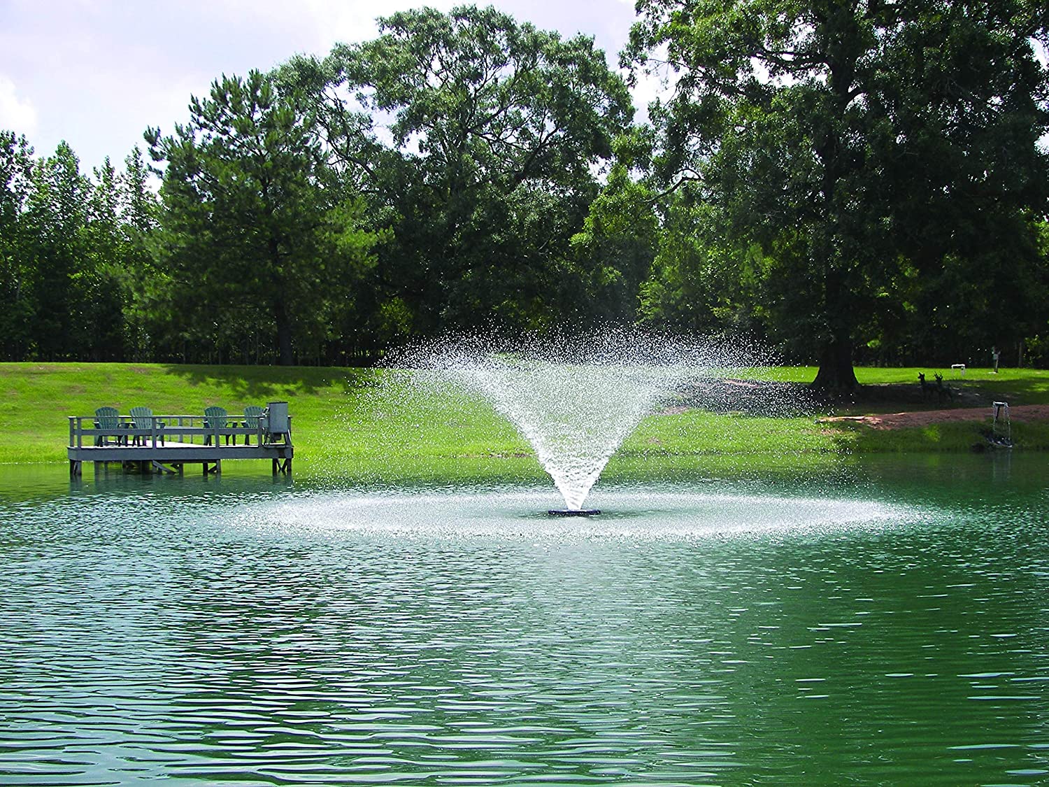
Kasco 8400VFX, 5.1VFX, 2.3VFX, 5.3VFX, 2.3HVFX, 5.3HVFX VFX Series Aerators
Important Safety:
Please read and follow these important instructions to help ensure your safety and the quality performance of your Kasco equipment.
- Caution should be used when dealing with any electrical and/or moving equipment.
- Under NO CIRCUMSTANCE should anyone enter the water with the electrical equipment plugged in and/or in operation.
- Kasco Aerating Fountains are intended for use with a Listed control panel having a GFCI protected receptacle, or field wiring terminals and disconnect switch, or a timer with a disconnect for use with a GFCI receptacle. Control panels MUST be installed by a qualified electrician. Ground Fault Circuit Interrupters (GFCIs) should be tested upon each installation and every month thereafter to ensure proper operation.
- Single-phase aerators are supplied with an internal grounding conductor and/or a grounding-type attachment plug. To reduce the risk of electrical shock, be certain the aerator is properly connected to the Kasco-supplied control panel (refer to the instructions included with your C-85 or C-95 Control Panel).
- 3-phase aerators (2.3VFX, 5.3VFX, 2.3HVFX, 5.3HVFX) require a startup test after wiring to ensure proper rotation of the propeller. If the propeller is rotating in the opposite direction, the unit will not perform properly and internal damage to the unit may occur (see 3-phase startup procedure on page 11).
- NEVER run the unit out of the water. This will damage the seals and create a dangerous situation for the operator.
- Extreme caution should be used around water, especially cold water, as in Spring, Fall, and Winter, which poses a hazard in and of itself.
- NEVER lift or drag the equipment by the power cords. If you need to pull the unit to the side of the pond, use the anchoring ropes.
- Do not use boats that tip easily for installation and follow all boating safety rules and regulations, including wearing a PFD (Personal Flotation Device). Do not use waders in deep ponds/lakes or ponds/lakes with drop-offs, drastic slopes, or soft bottom material.
- For more information regarding your control panel instructions, refer to your control panel owner’s manual. A control panel must be installed a minimum of 5 feet (3m in Canada) from the body of water unless separated from the body of water by a fence, wall, or other permanent barrier that will make the unit inaccessible to persons in the water. A complete list of control panels can be found in the Accessories section of kascomarine.com
Additional NotesDuring flotation operation, water is pulled from 360° around and directly below the unit. Keep these areas clear of debris as much as possible to decrease frequency of screen cleaning.
Tools and Supplies Needed
- (3) Anchors or stakes for installing unit
- 208/240VAC single-phase or 240VAC or 460VAC 3-phase electrical supply near pond on a post with room for mounting the supplied control panel
- (4) #10 x 1’’ long or longer screws for mounting the supplied control panel
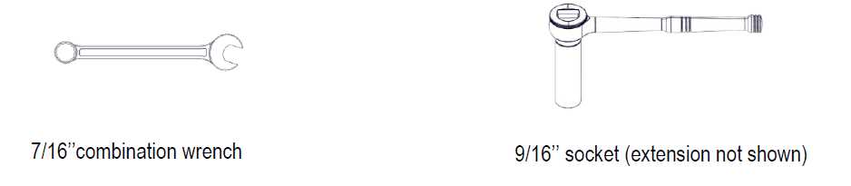
- 9/16’’ socket with extension and ratchet
- 7/16’’ socket and ratchet or combination wrench
- (3) 12’’ pieces of 1’’ galvanized pipe for weighting ropes (optional)
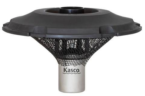
Parts Included

Assembly Instructions
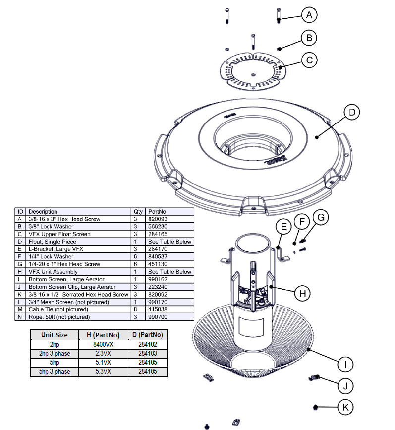
Step 1:Attach the float L-bracket (E) to the unit assembly (H) by tightening the 1/4’’ lock washer (F) and 1/4 – 20 x 1’’ hex head screw (G) with 7/16’’ socket or combination wrench. Repeat for all three legs on the unit assembly.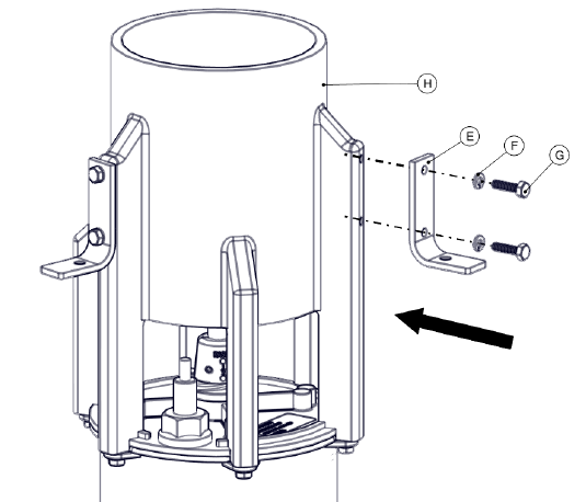
Step 2:Place the float (D) over the unit assembly so that it rests on the L-brackets. Ensure the three channels on the inside of the float line up with the threaded hole in the L-brackets, and the dedicated power cord channel on the underside of the float is near the cord connection on the unit assembly.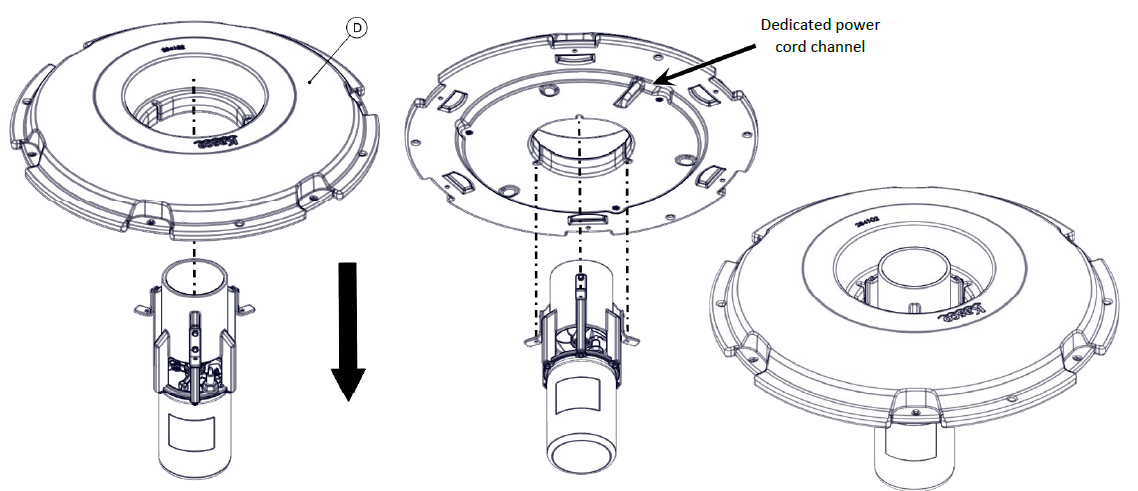
Step 3:Tighten the upper screen section (C) to the ledge on the top of the float using the 3/8 – 16 x 3’’ hex head screw (A) and 3/8’’ lock washer (B) through the hole in the L-bracket using the 9/16’’ socket wrench. Repeat for all three upper screen sections. Socket extension may be required.
Step 4:On the underside of the float, line up the (3) bottom screen clips (J) and start threading in the (3) 3/8 – 16 x 1/2’’ serrated hex head screws (K), but do not tighten down at this time. Be sure the clips can slide back and forth freely.

Step 5:Take the ¾’’ mesh screen (L) and wrap into a cone shape by overlapping both vertical edges by approximately 1 inch and aligning top and bottom edges of mesh as show n. Secure mesh vertical seam at the top, bottom and middle using (3) cable ties (M).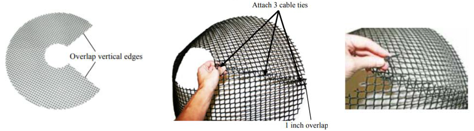
Step 6:Insert the metal bottom screen (I) inside the mesh cone with approximately 2 inches of mesh overhanging the top ring of the screen. Attach mesh to the top ring of the screen in (3) equally spaced locations using cable ties.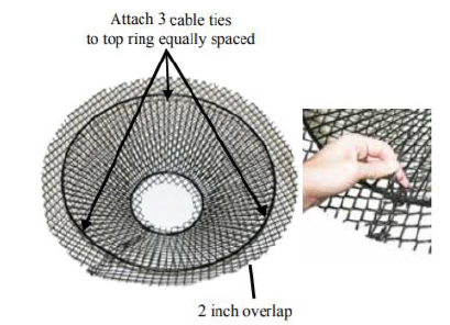
Step 7:Flip mesh and screen assembly over and use remaining cable ties to secure mesh to small bottom diameter of the bottom screen. Clip off excess cable ties once tightened and mesh is secured.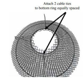
Step 8:Lift the unit and slide the bottom float screen (I) with the mesh over the can and up to the bottom of the float, allowing the unit power cord to exit between them in the dedicated channel.
Step 9:Slide the clips toward the center and over the bottom screen so that one of the vertical bars is between the two flanges on each clip as shown. Tighten all three serrated hex head screws to secure the screen to the bottom of the float, being sure not to pinch the power cord. 9/16’’ socket or combination wrench required.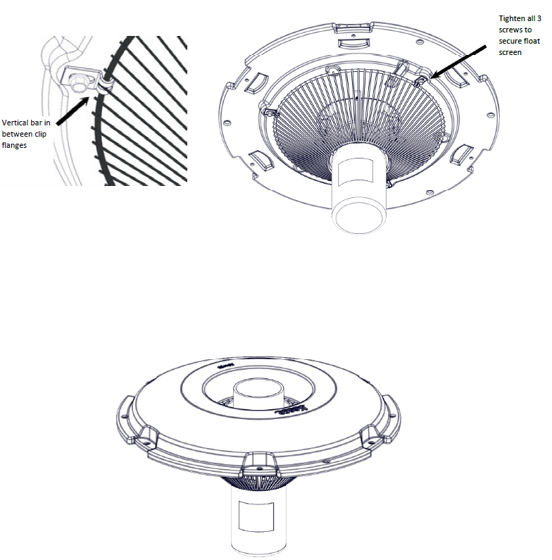
Installation Instructions
Note: Before installing 3-phase units (2.3VFX, 5.3VFX) into the pond, please refer to 3-phase startup procedure on page 11.Use ropes to position the aerator in the desired location in the pond or lake. Anchor the ropes or secure them to the shoreline so that they are free of slack, but not tight. To prevent twisting of the unit due to motor torque, place the anchor at least 3 feet from the float for each foot of depth (Ex. a 6ft deep pond would require an anchor 18ft horizontally from the float).
Alternate Installation:In ponds where the water level fluctuates significantly, a small weight may need to be suspended at the midpoint of the rope to take up any slack caused by a drop in water level (1 foot of 1’’ galvanized pipe works well). The weight should be light enough so the aerator can rise as the water level rises. This weight can also help hide the anchoring ropes by sinking them further below the surface.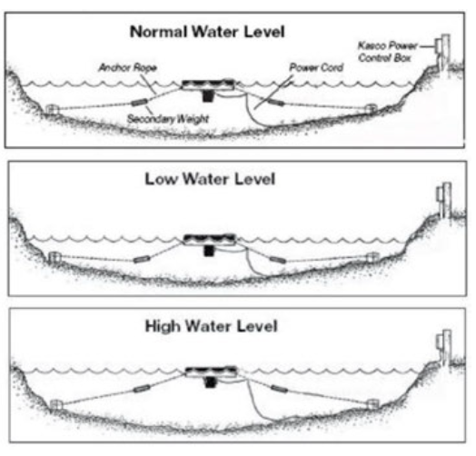
After VFX unit is installed in the water, connect the power cord to a properly installed Kasco control panel (C-85, C-95, etc.) with built-in ground fault protection according to the instructions and electrical schematics included with the panel. Follow all local and national electrical codes for unit and control panel installation; consult a qualified electrician or service person if needed. The aerator is ready to be turned on and enjoyed.
3-Phase Startup Procedure
For 3-Phase Units: 3-Phase Startup ProcedureIf a Kasco Control Panel is not provided, please refer to the following warnings:When inherent overheating protection is not provided: use with approved motor control that matches motor input in full load amperes with overload element(s) selected or adjusted in accordance with control instructions.Note: The motor input in full load amperes is the marked value or the service factor amperes, shown on the namplate.
Control panels must be installed by a qualified electrician.If unit is connected to a circuit protected by a fuse, use a time-delay fuse with this pump.You must verify motor rotation before installing the unit in the water. 3phase Kasco units will run in a clockwise rotation when looking down at the propeller. Stand clear of the propeller while verifying rotation. If a Kasco 3 phase panel is supplied, follow the instructions included with the panel in addition to the steps below.
Electrician:
- Verify all screw terminal connections are tightened to specified torque setting prior to energizing the panel.
- Verify the electrical service (voltage and phase) matches the control panel and aerator nameplates ratings. Refer to the control panel instructions and schematics for installation details.
- Verify all switches, circuit breakers, and motor starters are in the OFF position
- Connect electrical service to the control panel as shown in the electrical schematic that came with the panel.
- Connect the aerator power cord to the panel as shown in the electrical schematic.
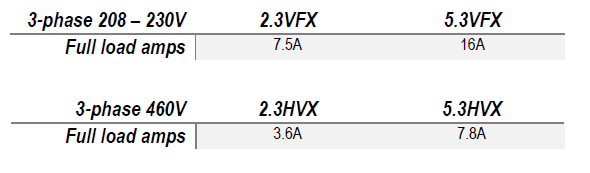
- Set the motor starter overload to the FLA rating on the aerator nameplate.
- Pump rotation: The pump rotation is clockwise when looking down at the propeller. Apply power to the control panel. Turn on the 15amp control circuit breaker, and motor starter.
- Momentarily turn the Hand-Off-Auto switch to Hand. This will run the aerator. Do not run the aerator for more than a few seconds on shore. If the rotation is not correct, disconnect and lock out power from the control panel. Swap any two of the aerator power cord wires in the panel. This will cause the motor to reverse direction. Reapply power to the panel and verify the rotation is clockwise.
- Once rotation is verified, with the power disconnected and locked out again, continue with installation of the aerator on page 9.
Maintenance Recommendations
Under NO CIRCUMSTANCE should anyone enter the water while a fountain is operating.The following maintenance procedures can be utilized to ensure many years of quality performance from your Kasco equipment and reduce the need for more costly repair work.
PROPER INSTALLATION: Proper installation of Kasco equipment will include a power source with ground fault protection. The control panel included with the equipment has built-in ground fault protection for both the fountain and the lighting kit. Ground fault interrupters are a safety feature that can also alert you to electrical leaks in the equipment. It is extremely important to test the GFI upon installation and every month thereafter to ensure proper operation. If you have repeat, consistent trips of the ground fault device, the equipment should be disconnected and removed from the water. The power cord should be inspected for damage and you should contact your distributor or contact Kasco Marine at 715-262-4488 or [email protected] for further instructions. A complete list of control panels can be found in the Accessories section of kascomarine.com.
OBSERVATION: Operating equipment should be observed on a regular basis (daily, if possible) for any reduction or variation in performance. If a change in performance is observed, the equipment should be disconnected from power and inspected.
WINTER STORAGE: In regions where there is significant freezing in the wintertime, the equipment should be removed from the water to protect it from the expansion pressure of ice. Aerators may keep some amount of ice open, but when water is thrust into the air it can make the existing ice thicker. Storage over winter is best in a location that is out of the sun and cool, but above 32° F. Store unit upside down if it will sit for a long period of time to ensure continued oil lubrication of seals; units that sit upright for many months or years have a greater likelihood of seals drying out.
CLEANING: Aerators should be removed from the water at least once per year (at the end of the season in cold climates) to clean the exterior of the system, especially the stainless-steel motor housing (can) that dissipates heat into the water. Any algae, calcium, or other build-up will become an insulator that blocks heat transfer and may lead to overheating and damage. In warmer regions, the unit should be removed and cleaned at least 2 – 3 times per year. In most cases, a power washer is sufficient if the unit and algae are still wet.
SEAL AND OIL REPLACEMENT: This is a sealed motor assembly and seals will wear out over time (similar to brake pads on a car). Replacement of the seals and a change of oil after three years may add longevity to the operation of the motor, saving you the cost of more expensive repairs. In warmer climates where the aerator runs for a majority the year or greater, it is wise to replace seals more often.
ZINC ANODE: A sacrificial zinc anode is supplied on the shaft of all VFX Model aerators for protection from corrosion and electrolysis. The zinc anode should be updated replaced if reduced to half the original size or if white in color. Corrosion from electrolysis is more commonly associated with saltwater or brackish water, but as a matter of precaution, it is important to periodically check the zinc anode in all installations (at least every two to three months).
Seal replacement and all other repair services should be performed by Kasco Marine or a Kasco-trained Authorized Repair Center. Any alterations or changes made to Kasco units by an unauthorized source will void the warranty. This includes tampering with the unit, power cord, and/or control panel. Contact Kasco Marine at 715-262-4488 or [email protected] for additional information and your closest Authorized Repair Center.
Warranty
Warranty Policy
Warranty period:2400VFX, 3400(H)VFX, 4400(H)VFX = 2-year Limited Warranty8400VFX, 2.3(H)VFX, 5.1VFX, 5.3(H)VFX = 3-year Limited WarrantyKasco® Marine, Inc. warrants this aerator to be free from defects in material or workmanship under normal use and service (excluding ropes, power cord, and propeller). The Kasco Marine, Inc. obligation under this warranty is limited to replacing or repairing free of charge any defective part within the warranty period from the date of shipment. Customer shall pay shipping charges for returning the unit to Kasco or an Authorized Repair Center.THIS WARRANTY IS IN LIEU OF ANY OTHER WARRANTIES, EXPRESSED OR IMPLIED, AND ANY OTHER OBLIGATION OR LIABILITY WHATEVER ON THE PART OF KASCO MARINE, INC. AND IN NO EVENT SHALL KASCO MARINE, INC. BE LIABLE FOR ANY SPECIAL OR CONSEQUENTIAL DAMAGES.
Warranty is void if:
- The aerator is not maintained properly according to the Maintenance Recommendations supplied in this Owner’s Manual.
- The aerator is returned for repair without the power cord
- The unit, control panel, or power cord are altered in any way from original shipment. Cuts in the power cord are not covered under warranty.
- The aerator is damaged by unauthorized tampering.
- The sacrificial zinc anode around the propeller shaft shows significant deterioration (not maintained according to Recommendations supplied in this Owner’s Manual)
Warranty Claim Procedure: The best method for establishing warranty period is by keeping your original receipt and registering the equipment online at kascomarine.com under the Warranty Information section.Once warranty coverage has been established, the unit may be sent to Kasco Marine or any Kasco Authorized Repair Center for evaluation and repair. See Repair section on the next page for more information regarding warranty repair procedure.
Repair
Note: Only complete motor assemblies will be accepted for warranty repair. The power cord and all other components must be returned with the motor as originally assembled. Any missing parts will be replaced at the customer’s expense and, if determined to have caused the failure, could void the entire warranty. Some parts are essential for structural support during shipping and others, such as the power cord, are essential to properly diagnose potential causes of failure. It is not necessary to return the control box or float with the motor assembly.
Any required repairs must be performed by Kasco Marine. Any alterations or changes made to Kasco units by an unauthorized source will void the warranty. This includes tampering with the unit, power cord, and/or control box.A physical Kasco Repair Form must be included with any equipment sent to Kasco or an Authorized Repair Center. This form can be found under the Product Support section of kascomarine.com. If no Repair Form is available, include your name and physical address for return delivery of the repaired unit and a daytime phone number and/or e-mail address for correspondence regarding the warranty claim.Once warranty coverage has been established, the equipment may be sent to any Kasco Authorized Repair Center or to Kasco at:
Kasco Marine, Inc.800 Deere Rd.Prescott, WI 54021Attn: Repairs
Non-Warranty Repairs: Most failed equipment can be repaired at substantially lower costs than replacement with new. If your aerator requires repair and is no longer covered under warranty, please contact Kasco Marine or your local distributor for available options. Please ship according to the instructions above.
- Kasco Marine does estimates on repairs at the request of the customer. The request for estimate should be included in the letter that accompanies the returned unit and must include a daytime phone number and/or e-mail address. We will contact the customer with a total after the unit has been evaluated, but before the work is performed.
- All estimates that are rejected for repair will be destroyed unless otherwise directed by the customer. Rejected equipment can be returned at the customer’s expense for shipping and handling charges.
Billing: All non-warranty repairs will be returned and billed to the customer unless otherwise directed. Kasco Marine accepts Visa and MasterCard credit card payments. Kasco Marine will call for credit card information upon completion of the estimate at the customer’s request.Please see the Product Support section of kascomarine.com for more information about warranty and repairs. Contact Kasco Marine at 715-262-4488 or [email protected] for additional information and your closest Authorized Repair Center.
Troubleshooting Tips
The following is provided to help diagnose a probable source of trouble. It is a guideline only and may not show all causes for all problems. For additional troubleshooting help, contact your local distributor or visit kascomarine.com for additional guidance.Note: you may need to refer to your owners manual that was provided with your control panel for additional control panel settings and adjustments. “My Aerator trips the ground fault interrupter in the C-25, C-85, or C-95.”
This is the most common symptom of several possible problems. To correctly diagnose the problem, you will need to collect more information. A Ground Fault Interrupter (GFI) breaker that trips can indicate an electrical service problem, water contamination in the unit and/or cord, bad breaker, control box problems, motor problems, etc. Try to find out the answers to these questions before you contact Kasco to narrow down the problem:
- How long does it take to trip the breaker?
- Does it always take the same amount of time to trip?
- How many times has it tripped?
- Has there been any electrical problems in the area recently?
“My Aerator seems to run slowly.”This can also be a symptom of several possible problems. There could be an electrical problem where the unit is not getting the proper voltage. This could also indicate a problem with the motor of the unit, which needs to be looked at by an Authorized Repair Center. Check that the unit is receiving the proper voltage, and, if so, contact Kasco for further steps.
“My Aerator hums, but will not start. When I spin the prop with a stick, it starts up.”(single phase units only) This indicated a problem with the Starting Capacitor. Each Kasco aerator is equipped with a Starting Capacitor to get the unit going when it is first plugged in. If it is operating, but not spinning and can be started by spinning the prop with a stick, the Starting capacitor needs to be replaced by an Authorized Repair Center.
“My Aerator turns itself off and back on without the timer and without tripping the GFI breaker.”(single phase units only) Each Kasco aerator has a Thermal Overload built in that will turn the unit off when it overheats. Once the unit has cooled down, it will start back up. If you are noticing these symptoms, the unit should be unplugged immediately because the Thermal Overload will continue to turn on and off until it burns out and damages the motor. The unit should be unplugged and taken out of the water to find the cause of the problem. The problem could be one of many, such as, low water levels, build-up on the unit to prevent heat dissipation, something inhibiting the free rotation of the shaft, etc. If something is caught in the unit or there is a build-up of algae, calcium or organic matter on the unit, remove the debris and, if caught early enough, the unit should 22 be fine. Contact a Kasco representative before restarting the unit.“My Aerator flow seems to fluctuate and/or be less than usual.”
This can occur because of a few different reasons. Most of the time, this symptom is caused from unit being clogged with debris. A mat of weeds, many leaves, plastic bags, etc. can clog up the unit and cause it to be starved of water. If the unit does not have the proper amount of water, the flow or pattern will fluctuate up and down and look sporadic. If you are seeing these symptoms, unplug the unit and clean away the debris that is clogging up the screen. Another possibility if these symptoms are noticed, is a chipped or damaged prop that is causing the unit to wobble and not pump properly. When the unit is unplugged, check the prop for damages and replace if damage is found.“The GFI breaker trips randomly and sporadically. Sometimes it is a few hours of operation, other times it can be days or weeks.”
This is referred to as a Nuisance Trip. This usually occurs where the unit is installed a great distance from the initial electric service on the property where the ground stake is placed. It is caused by either induced current in the ground wire or a base voltage difference due to soil pH levels. To resolve the problem, contact an electrician and install a local grounding stake. This may eliminate the induced current and any base voltage differences. This problem can also be caused by a bad breaker or receptacle or having unbalanced incoming voltage lines.
Replacement Parts
![]() 800 Deere RdPrescott, WI 54021Phone: 715-262-4488 Fax: 715-262-4487www.Kascomarine.com [email protected]
800 Deere RdPrescott, WI 54021Phone: 715-262-4488 Fax: 715-262-4487www.Kascomarine.com [email protected]
References
[xyz-ips snippet=”download-snippet”]