

Owners Manual
RGB3C5, RGB6C5WaterGlow Lighting
Kasco Marine, Inc.800 Deere Rd.Prescott, WI 54021PH (715) 262-4488kascomarine.com
Manual Number884102
Rev 7/20
Important Safety:
Please read and follow these important instructions to help ensure your safety and the quality performance of your Kasco equipment.
- Caution should be used when dealing with any electrical and/or moving equipment.
- Under NO CIRCUMSTANCE should anyone enter the water with the electrical equipment plugged in and/or in operation.
- Kasco WaterGlow lighting kits are intended for use with a Listed control panel having a GFCI protected receptacle, or field wiring terminals and disconnect switch, or a timer with a disconnect for use with a GFCI receptacle. They are intended to be mounted on a floating fountain or aerator for use in a natural or man-made body of water to comply with NEC Article 682.
- Kasco WaterGlow lighting kits have not been evaluated for use in swimming pools, spas or stationary fountains.
- RGBC5 controller is 120Vac and MUST be plugged into a GFCI protected receptacle or GFCI protected field terminal connections.
- RGBC5 fixtures MUST be properly submerged (approx. halfway) to avoid overheating; insufficient submersion or operation out of water will damage fixtures and void warranty.
- Extreme caution should be used around water, especially cold water, as in Spring, Fall, and Winter, which poses a hazard in and of itself.
- NEVER lift or drag the equipment by the power cords. If you need to pull the unit to the side of the pond, use the anchoring ropes.
- Do not use boats that tip easily for lighting kit installation and follow all boating safety rules and regulations, including wearing a PFD (Personal Flotation Device). Do not use waders in deep ponds/lakes or ponds/lakes with drop-offs, drastic slopes, or soft bottom material.
- For more information regarding your control panel instructions, refer to your equipment owner’s manual. A control panel must be installed a minimum of 5 feet (3m in Canada) from the body of water unless separated from the body of water by a fence, wall, or other permanent barrier that will make the unit inaccessible to persons in the water. A complete list of control panels can be found in the Accessories section of kascomarine.com.
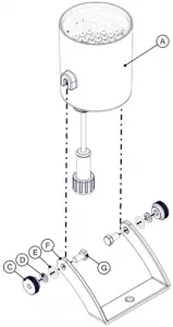
Parts Included
| ID | Description | Qty* | PartNo |
| A | RGBC5 Fixture | 3 | 347000 |
| B | Cord Connector O-ring | 3 | 345035 |
| C | 10-32 Thumb Nut | 6 | 345043 |
| D | #10 Split Lock Washer | 6 | 771037 |
| F | Composite Light Bracket | 3 | 345007 |
| G | 10-32 x 1/2″ Hex Screw | 6 | 345042 |
| H | Snap-On Light Clip | 3 | 361445 |
| I | 1/4-20 x 1-3/8″ Hex Bolt | 3 | 584692 |
| J | 1/4″ Flat Washer | 3 | 258476 |
| K | 1/4″ Split Lock Washer | 3 | 840537 |
| L | 1/4-20 Nut | 3 | 840536 |
| M | Cable Tie (not pictured) | 3 | 415038 |
| N | RGB Control Panel (not pictured) | 1 | 130030 |
*Double quantities A M for 6-light kit

Mounting Instructions
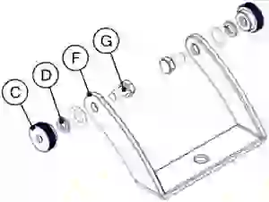
Step 1Attach the bracket (F) to the light fixture (A) by fitting the head of the 10-32 x 1/2” hex screw (G) into the tabs on each side of the fixture. Place one bracket O-ring (E), one #10 lock washer (D), and one thumb nut (C) on each #10 screw outside the bracket. Tighten the thumb screws on each side hand tight only. Repeat this step for all fixtures.

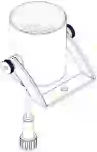
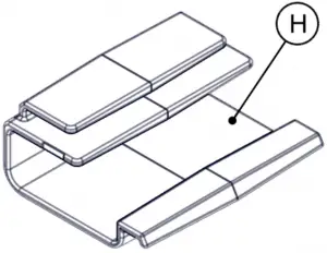
Step 2Slide bracket into the top flange on the snap-on clip (H) until it clicks into place and is secure.Note: For 1/2, 3/4, & 1HP AF units:Use alternate hardware instead of the snap-on light clip, following directions on page 6.
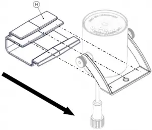

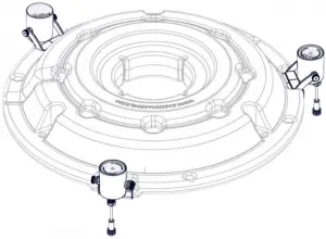
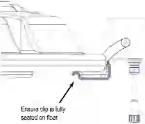
Step 3After attaching unit to the float according to fountain/aerator instructions, push clips into recesses on float until an audible click is heard and fixture is secure.
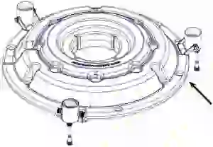
Step 4Repeat for remaining fixtures, spacing evenly around the float. Adjust angle of lights using thumb nuts if desired, being sure that the same angle is used for all fixtures. Cable ties can be used to attach fixture cords to float to decrease play and ensure protection. Cable tie light kit power cord to float opposite the fountain power cord for balance and to prevent damage from fountain.
 Secure light kit power cord to float using supplied cable tie
Alternate Mounting Instructions
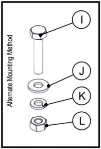
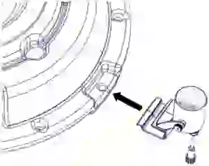
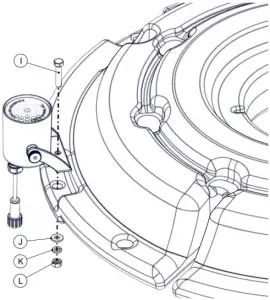
For J/VFX units:Included with the light kit is optional hardware for use instead of the snap-on light clip. Assemble parts I, J, K, and L as shown in the diagram below and tighten until secure. 7/16” socket and wrench required.
For 1/2, 3/4, & 1HP AF units:Use alternate hardware instead of the snap-on light clip, following directions above and continuing to step 4 on page 5.
For Large Surface Aerator units:To mount RGBC5 light fixtures to a large (2HP+) surface aerator, supplementary hardware to what is included in a standard kit is needed. Additional hardware kit P/N 840303 (for 3 light fixtures) or 840306 (for 6 light fixtures) must be used (sold separately; contact Kasco Marine at [email protected] or your local distributor for order information).
RGB Control Panel Installation & Operation
Step 5Open the control box and remove the operating instruction sheet, remote control, and battery. Insert the battery into the remote control. If the battery is already inserted, remove the plastic battery guard from the remote to active the battery connection.
Step 6The RGB control box is ready to mount next to your Kasco fountain control box (mount a minimum of 5ft from water) using two exterior-grade wood screws; one for the top and one for the bottom hanger. Tighten the top screw to prevent the box from lifting off the screws. Mount close enough for the power cord to reach the receptacle or terminals labeled “Lights” in the fountain control box.
Note: Do NOT power on RGB control box at this time.
Step 7Once mounted, connect the RGB light kit power cord to the field terminal connections in the RGB control box. Connect: White to White, Green to Green, Red to Red, and Black to Black.
Step 8For 120V fountain control box: Plug the RGB control box into the “Lights” receptacle in the fountain control box. This will allow the C-25 control panel to control the lights and the fountain through the timer. To energize the C-25 light receptacle, the photoeye of the C-25 will need to be covered (to simulate nighttime conditions). Refer to your C-25 instructions.
For 240V or 3phase fountain control box: If you have a Kasco C-85, C-95 or 3phase control panel, you will need to hardwire the RGB controller power cord to the light terminals in your fountain control panel. Refer to your fountain owner’s manual for connection information. The Kasco C-85, C-95, and 3phase control panels use a timer for controlling the light output. Ensure the light timer is set as required. Refer to your fountain owner’s manual for timer setting instructions.
Step 9With the RGB controller door open, a red LED “Power” indicator on the RGB control module will be seen. If this indicator is not on, then power is not being sent to the RGB control box.
Step 10 - RGB OperationThe RGB controller is operated with the included remote control. The controller will operate in the last mode set until it is changed with the remote. Before use, remove the clear plastic tab at the base of the remote. The figure below details the remote control’s functions. The green signal indicator (on the RGB controller) will flash while the remote is communicating to the controller.
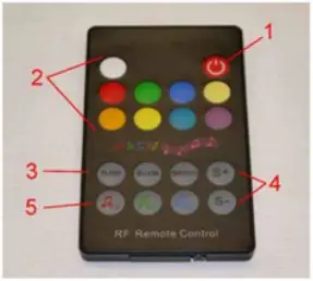
- Power On/Off: press the button once to turn on, again to turn off.
- 9 static color modes: White, Red, Green, Blue, Warm White, Amber, Yellow, Cyan, Magenta. Repeatedly pressing the color will cycle the intensity at 100%, 50%, 25%, 12%, 6% and back to 100%.
- Automatic color sequencing modes: Flash jump to next color; Bloom-transition from color to color; Smooth smooth transition from color to color
- S+, S- button slow down or speed up the color transitions of the 3 automatic modes
- Music input control: The RGB controller is capable of changing colors based on sound input. The controller has a 3.5mm audio jack, and a a microphone built into the controller. The microphone input is adjustable with a level sensitivity dial.
Music Control
The remote control has 3 automatic music modes:
- FT - Fast track, color change is fast change
- MT - My track, color change is medium changing speed
- CT - Cool track, color change is slower and smoother than FT, and MT.
The audio input jack is compatible with the headphone jack on a smartphone, MP3 player, or a pre-amp type output via an “aux” style 3.5mm connection. Do not connect to a line level (amplified speaker) output. Kasco recommends a 3.5mm “Y” adapter to allow for connection of the audio source to the RGB controller and a stereo amplifier simultaneously if desired.
Maintenance Recommendations
Under NO CIRCUMSTANCE should anyone enter the water while a fountain is operating.
The following maintenance procedures can be utilized to ensure many years of quality performance from your Kasco Fountain and Light Kit and reduce the need for more costly repair work.
PROPER INSTALLATION: Proper installation of Kasco equipment will include a power source with ground fault protection. The control panel included with the equipment has built-in ground fault protection for both the fountain and the lighting kit. Ground fault interrupters are a safety feature that can also alert you to electrical leaks in the equipment. If you have repeat, consistent trips of the ground fault device, the equipment should be disconnected and removed from the water. The power cord should be inspected for damage and you should contact your distributor or contact Kasco Marine at 715-262-4488 or [email protected] for further instructions. A complete list of control panels can be found in the Accessories section of kascomarine.com.
OBSERVATION: Operating equipment should be observed on a regular basis (daily, if possible) for any reduction or variation in performance. If a change in performance is observed, the equipment should be disconnected from power and inspected.
WINTER STORAGE: In regions where there is significant freezing in the wintertime, the light kit should be removed from the water to protect it from the expansion pressure of ice. Storage over winter is best in a location that is out of the sun and cool, but above 32° F.
CLEANING: Light kits should be removed from the water at least once per year (at the end of the season in cold climates) to clean the exterior of the system. The light fixture surfaces dissipate heat into the water and any algae, calcium, or other build-up will become an insulator that blocks heat transfer and may lead to overheating and damage. Keeping the lenses clean will also ensure the brightest light possible.
Warranty
Warranty Policy
Warranty period: RGB3C5, RGB6C5 = 2 year Limited Warranty: Kasco® Marine, Inc. warrants this Light Kit to be free from defects in material or workmanship under normal use and service. The Kasco Marine, Inc. obligation under this warranty is limited to replacing or repairing free of charge any defective part within the warranty period from the date of shipment. Customer shall pay shipping charges for returning the unit to Kasco.
THIS WARRANTY IS IN LIEU OF ANY OTHER WARRANTIES, EXPRESSED OR IMPLIED, AND ANY OTHER OBLIGATION OR LIABILITY WHATEVER ON THE PART OF KASCO MARINE, INC. AND IN NO EVENT SHALL KASCO MARINE, INC. BE LIABLE FOR ANY SPECIAL OR CONSEQUENTIAL DAMAGES. (Warranty Policy continued on next page)
Warranty is void if:
- The Light Kit is not maintained properly according to the Maintenance Recommendations supplied in this Owner’s Manual.
- The lights, control box, or power cord are altered in any way from original shipment. Cuts in the power cord are not covered under warranty.
- The Light Kit is damaged by unauthorized tampering.
Warranty Claim Procedure: The best method for establishing warranty period is by keeping your original receipt and registering the equipment online at kascomarine.com under the Warranty Information section.
Once warranty coverage has been established, the light kit may be sent to Kasco Marine or any Kasco Authorized Repair Center for evaluation and repair.
Repair
Note: The LED light fixtures are sealed and do not require any physical maintenance other than cleaning. If a fixture fails to operate it can be removed and the included sealing cap installed onto the waterproof connector of the power cord. This will allow you to continue to operate your light kit with two fixtures while a replacement fixture is procured. Utilize caution when removing the shrink tube from the connector. Only perform this removal/replacement with all equipment disconnected from the power source.
Any required repairs must be performed by Kasco Marine. Any alterations or changes made to Kasco units by an unauthorized source will void the warranty. This includes tampering with the unit, power cord, and/or control box.
A physical Kasco Repair Form must be included with any equipment sent to Kasco or an Authorized Repair Center. This form can be found under the Product Support section of kascomarine.com. If no Repair Form is available, include your name and physical address for return delivery of the repaired Light Kit and a daytime phone number and/or e-mail address for correspondence regarding the warranty claim.
Note: Visually inspect the power cord for any cuts, rodent chews, etc. to determine if it should be included in the repair shipment. The cord may be needed by the shop to diagnose the failure.
Once warranty coverage has been established, the equipment may be sent to any Kasco Authorized Repair Center or to Kasco at:
Kasco Marine, Inc.800 Deere Rd.Prescott, WI 54021Attn: Repairs
Non-Warranty Repairs: Most failed equipment can be repaired at substantially lower costs than replacement with new. If your light kit requires repair and is no longer covered under warranty, please contact Kasco Marine or your local distributor for available options. Please ship according to the instructions above.
- Kasco Marine does estimates on repairs at the request of the customer. The request for estimate should be included in the letter that accompanies the returned unit and must include a daytime phone number and/or e-mail address. We will contact the customer with a total after the unit has been evaluated, but before the work is performed.
- All estimates that are rejected for repair will be destroyed unless otherwise directed by the customer. Rejected equipment can be returned at the customer’s expense for shipping and handling charges.
Billing: All non-warranty repairs will be returned and billed to the customer unless otherwise directed. Kasco Marine accepts Visa and MasterCard credit card payments. Kasco Marine will call for credit card information upon completion of the estimate at the customer’s request.
Please see the Product Support section of kascomarine.com for more information about warranty and repairs. Contact Kasco Marine at 715-262-4488 or [email protected] for additional information and your closest Authorized Repair Center.
Troubleshooting Tips
The following is provided to help diagnose a probable source of trouble. It is a guideline only and may not show all causes for all problems. For additional troubleshooting help, contact your local distributor or visit kascomarine.com for additional guidance. Note: you may need to refer to your owners manual that was provided with your fountain for additional control panel settings and adjustments.
“My light kit is installed and wired but will not turn on.”
Ensure control panel is connected to the electrical circuit. Verify circuit breakers, timers, and/or interlock switches are turned on and functional. Refer to your owners manual that was provided with the fountain.
It may not be dark enough for the photo eye on the control panel to activate.
- C-25 control panel: The control panel has a photo eye on the left side of the enclosure exterior. This photo eye measures ambient light. To activate, the photo eye must not measure any ambient light for at least several minutes. Also, the C-25 timer must be turned on (fountain operating) to allow the light circuit to energize. Covering the photo eye with black electrical tape will activate the photo eye for testing.
- C-85, or C-95 control panel with GFCI outlet and photo eye control: The control panel has a photo eye on the left side of the enclosure exterior. This photo eye measures ambient light. To activate, the photo eye must not measure any ambient light for at least several minutes. Also, the fountain timer must be turned on (fountain operating) to allow the light circuit to energize. Covering the photo eye with black electrical tape will activate the photo eye for testing. While the photo eye is covered, the GFCI outlet can be reset if tripped.
The timer may not be set properly.
- C-85, or C-95 control panel (and all 3phase fountain control panels) with terminal connections and timer control for light kit: The control panel has a second timer for controlling the lights (no photo eye). Ensure the light timer is set to operate the lights. The timer has a built in Hand-Off-Auto switch. Ensure the switch is set properly. Ensure the fountain is turned on. The light timer will not energize the light kit unless the fountain circuit is energized.
The GFCI may be tripped.
- C-25 control panel: Reset the GFCI. If the GFCI does not reset it could be a ground fault in the fountain wiring, or the light kit wiring. Unplug both the fountain and light kit and reset the GFCI. If it resets, plug fountain then light kit back in and see which one trips the GFCI. If the GFCI does not reset with both unplugged, then the GFCI may be defective.
- C-85, or C-95 control panel with GFCI outlet and photo eye control: To reset the GFCI outlet the fountain timer must be turned on, and the photo eye must be activated. (black electrical tape can be wrapped around the photo eye to activate it). Once these are on, the GFCI reset button can be pressed. (unplug the light kit prior). Plug the light kit in and see if it operates. If the GFCI trips again then the light kit may be damaged. If the GFCI does not reset (with light kit unplugged) then it may be defective, or the photo eye is not activated to send power to the outlet.
- C-85, or C-95 control panel with terminal connections and timer control for light kit: For panels with a GFCB (ground fault circuit breaker) and timer-controlled lights, simply reset the two-pole breaker. This will turn the fountain and light kit back on if the timers are set to on! If it trips again, disconnect the light kit from the terminals and reset. WARNING! You must turn off power to the panel before disconnecting any wiring from the terminals! If the breaker trips with the light kit disconnected, then disconnect the fountain as well and reset. If the breaker continues to trip it may be a defective GFCB. If the breaker resets, then reconnect the fountain then the light kit to see which one trips the GFCB.
- 3phase fountain control panels: 3phase fountain panels have a ground fault sensing module that will trip if either the light kit or fountain has a ground fault. To reset the module, simply press the reset button in the panel. This will turn the fountain and light kit back on if the timers are set to on! If it trips again, disconnect the light kit from the terminals and reset. WARNING! You must turn off power to the panel before disconnecting any wiring from the terminals! If the GFI module trips with the light kit disconnected, then disconnect the fountain as well and reset. If the GFI module continues to trip it may be a defective module or an internal wiring issue with the panel. If the module resets, then reconnect the fountain then the light kit to see which one trips the module.
“My lights work, but they are not as bright as they were when fist installed.”
Dirty lenses may be to blame.
- Turn off power to the control panel and disconnect power cords to the fountain and the light kit. Bring the fountain to the shore and inspect the light kit lenses. Over time, algae growth and hard water deposits on the lenses can block light output. Clean the lenses with a soft brush and the light should be bright again.
“I’ve connected my audio device to the controller with an aux cord, but my lights are not changing color.”
The wrong setting or a low input signal could be the problem.
- Be sure that one of the 3 automatic music modes are enabled.
- Turn up the volume of the audio source.
Replacement Parts
| ID | Description | Qty* | PartNo |
| A | RGBC5 Fixture | 3 | 347000 |
| B | Cord Connector O-ring | 3 | 345035 |
| C | 10-32 Thumb Nut | 6 | 345043 |
| D | #10 Split Lock Washer | 6 | 771037 |
| F | Composite Light Bracket | 3 | 345007 |
| G | 10-32 x 1/2″ Hex Screw | 6 | 345042 |
| H | Snap-On Light Clip | 3 | 361445 |
| I | 1/4-20 x 1-3/8″ Hex Bolt | 3 | 584692 |
| J | 1/4″ Flat Washer | 3 | 258476 |
| K | 1/4″ Split Lock Washer | 3 | 840537 |
| L | 1/4-20 Nut | 3 | 840536 |
| M | Cable Tie (not pictured) | 3 | 415038 |
| N | RGB Control Panel (not pictured) | 1 | 130030 |
*Double quantities A - M for 6-light kit
![]()
800 Deere RdPrescott, WI 54021Phone: 715-262-4488 Fax: 715-262-4487www.Kascomarine.com [email protected]
Repair Contact Form
- Kasco requires all Repairs sent in MUST be accompanied by this form and marked to Repairs attention. (ex. Attn: Repairs)
- Repairs returned should include upper pump housing or wire basket for Aerators and De-Icers. These parts protect the motor during shipping.
- Kasco is NOT responsible for shipping damage accrued in return shipment.
- It is the responsibility of customer to ship and pay freight to Kasco.
- Do not ship float or control panel with unit, unless otherwise instructed
- A fee of $60 per hour will be assessed for cleaning excessively dirty units and float disassembly
- Refer to the Owner’s manual for easy-to-follow troubleshooting rule out site issue.
Note: Contact Information Should be that of the person or company to contact for repair.
| Company | First Name | Last Name |
| Address | City | State |
| Zip code | Phone # | Alternate Phone # |
| Email Address | Preferred method of contact (Circle)
Phone Email |
Purchase order # |
| Submersible Pump Information (Complete if sending unit) | Light kit Information (complete if sending lights) | Parts Included (For office use) |
| Model # | Model # | Unit |
| Serial # | Serial # | Cord |
| Cord Length: | Cord Length: | Light Kit |
| Purchased from: | Purchased From | Float |
| Purchase Date: | Purchase Date: | Control Panel |
Additional notes for technician.
References
[xyz-ips snippet=”download-snippet”]