![]()
Model 2657A High Power SourceMeter InstrumentQuick Start Guide

Safety precautions
The following safety precautions should be observed before using this product and any associated instrumentation. Although some instruments and accessories would normally be used with nonhazardous voltages, there are situations where hazardous conditions may be present.This product is intended for use by personnel who recognize shock hazards and are familiar with the safety precautions required to avoid possible injury. Read and follow all installation, operation, and maintenance information carefully before using the product. Refer to the user documentation for complete product specifications.If the product is used in a manner not specified, the protection provided by the product warranty may be impaired.The types of product users are:The responsible body is the individual or group responsible for the use and maintenance of equipment, for ensuring that the equipment is operated within its specifications and operating limits, and for ensuring that operators are adequately trained.Operators use the product for its intended function. They must be trained in electrical safety procedures and proper use of the instrument. They must be protected from electric shock and contact with hazardous live circuits.Maintenance personnel performs routine procedures on the product to keep it operating properly, for example, setting the line voltage or replacing consumable materials. Maintenance procedures are described in the user documentation. The procedures explicitly state if the operator may perform them. Otherwise, they should be performed only by service personnel.Service personnel is trained to work on live circuits, perform safe installations, and repair products. Only properly trained service personnel may perform installation and service procedures.Keithley products are designed for use with electrical signals that are measurement, control, and data I/O connections, with low transient overvoltages, and must not be directly connected to mains voltage or to voltage sources with high transient overvoltages. Measurement Category II (as referenced in IEC 60664) connections require protection for high transient overvoltages often associated with local AC mains connections. Certain Keithley measuring instruments may be connected to mains. These instruments will be marked as category II or higher.Unless explicitly allowed in the specifications, operating manual, and instrument labels, do not connect any instrument to mains.Exercise extreme caution when a shock hazard is present. Lethal voltage may be present on cable connector jacks or test fixtures. The American National Standards Institute (ANSI) states that a shock hazard exists when voltage levels greater than 30 V RMS, 42.4 V peak, or 60 VDC are present. A good safety practice is to expect that hazardous voltage is present in any unknown circuit before measuring.Operators of this product must be protected from electric shock at all times. The responsible body must ensure that operators are prevented access and/or insulated from every connection point. In some cases, connections must be exposed to potential human contact. Product operators in these circumstances must be trained to protect themselves from the risk of electric shock. If the circuit is capable of operating at or above 1000 V, no conductive part of the circuit may be exposed.Do not connect switching cards directly to unlimited power circuits. They are intended to be used with impedance-limited sources. NEVER connect switching cards directly to AC mains. When connecting sources to switching cards, install protective devices to limit fault current and voltage to the card.Before operating an instrument, ensure that the line cord is connected to a properly grounded power receptacle. Inspect the connecting cables, test leads, and jumpers for possible wear, cracks, or breaks before each use.When installing equipment where access to the main power cord is restricted, such as rack mounting, a separate main input power disconnect device must be provided in close proximity to the equipment and within easy reach of the operator.For maximum safety, do not touch the product, test cables, or any other instruments while power is applied to the circuit under test. ALWAYS remove power from the entire test system and discharge any capacitors before: connecting or disconnecting cables or jumpers, installing or removing switching cards, or making internal changes, such as installing or removing jumpers.
Do not touch any object that could provide a current path to the common side of the circuit under test or power line (earth) ground. Always make measurements with dry hands while standing on a dry, insulated surface capable of withstanding the voltage being measured.For safety, instruments and accessories must be used in accordance with the operating instructions. If the instruments or accessories are used in a manner not specified in the operating instructions, the protection provided by the equipment may be impaired.Do not exceed the maximum signal levels of the instruments and accessories. Maximum signal levels are defined in the specifications and operating information and shown on the instrument panels, test fixture panels, and switching cards. When fuses are used in a product, replace them with the same type and rating for continued protection against fire hazards. Chassis connections must only be used as shield connections for measuring circuits, NOT as protective earth (safety ground) connections.If you are using a test fixture, keep the lid closed while power is applied to the device under test. Safe operation requires the use of a lid interlock.If a ![]() screw is present, connect it to protective earth (safety ground) using the wire recommended in the user documentation.The
screw is present, connect it to protective earth (safety ground) using the wire recommended in the user documentation.The ![]() symbol on an instrument means caution, risk of hazard. The user must refer to the operating instructions located in the user documentation in all cases where the symbol is marked on the instrument.The
symbol on an instrument means caution, risk of hazard. The user must refer to the operating instructions located in the user documentation in all cases where the symbol is marked on the instrument.The ![]() symbol on an instrument means warning, risk of electric shock. Use standard safety precautions to avoid personal contact with these voltages.The
symbol on an instrument means warning, risk of electric shock. Use standard safety precautions to avoid personal contact with these voltages.The ![]() symbol on an instrument shows that the surface may be hot. Avoid personal contact to prevent burns.The
symbol on an instrument shows that the surface may be hot. Avoid personal contact to prevent burns.The ![]() symbol indicates a connection terminal to the equipment frame.If this
symbol indicates a connection terminal to the equipment frame.If this ![]() symbol is on a product, it indicates that mercury is present in the display lamp. Please note that the lamp must be properly disposed of according to federal, state, and local laws.
symbol is on a product, it indicates that mercury is present in the display lamp. Please note that the lamp must be properly disposed of according to federal, state, and local laws.
The WARNING heading in the user documentation explains hazards that might result in personal injury or death. Always read the associated information very carefully before performing the indicated procedure.The CAUTION heading in the user documentation explains hazards that could damage the instrument. Such damage may invalidate the warranty.The CAUTION heading with the ![]() symbol in the user documentation explains hazards that could result in moderate or minor injury or damage to the instrument. Always read the associated information very carefully before performing the indicated procedure. Damage to the instrument may invalidate the warranty.Instrumentation and accessories shall not be connected to humans.Before performing any maintenance, disconnect the line cord and all test cables.To maintain protection from electric shock and fire, replacement components in mains circuits — including the power transformer, test leads, and input jacks — must be purchased from Keithley. Standard fuses with applicable national safety approvals may be used if the rating and type are the same. The detachable mains power cord provided with the instrument may only be replaced with a similarly rated power cord. Other components that are not safety-related may be purchased from other suppliers as long as they are equivalent to the original component (note that selected parts should be purchased only through Keithley to maintain the accuracy and functionality of the product). If you are unsure about the applicability of a replacement component, call a Keithley office for information.Unless otherwise noted in product-specific literature, Keithley instruments are designed to operate indoors only, in the following environment: Altitude at or below 2,000 m (6,562 ft); temperature 0 °C to 50 °C (32 °F to 122 °F); and pollution degree 1 or 2.To clean an instrument, use a cloth dampened with deionized water or mild, water-based cleaner. Clean the exterior of the instrument only. Do not apply cleaner directly to the instrument or allow liquids to enter or spill on the instrument. Products that consist of a circuit board with no case or chassis (e.g., a data acquisition board for installation into a computer) should never require cleaning if handled according to instructions. If the board becomes contaminated and operation is affected, the board should be returned to the factory for proper cleaning/servicing.Safety precaution revision as of June 2017.
symbol in the user documentation explains hazards that could result in moderate or minor injury or damage to the instrument. Always read the associated information very carefully before performing the indicated procedure. Damage to the instrument may invalidate the warranty.Instrumentation and accessories shall not be connected to humans.Before performing any maintenance, disconnect the line cord and all test cables.To maintain protection from electric shock and fire, replacement components in mains circuits — including the power transformer, test leads, and input jacks — must be purchased from Keithley. Standard fuses with applicable national safety approvals may be used if the rating and type are the same. The detachable mains power cord provided with the instrument may only be replaced with a similarly rated power cord. Other components that are not safety-related may be purchased from other suppliers as long as they are equivalent to the original component (note that selected parts should be purchased only through Keithley to maintain the accuracy and functionality of the product). If you are unsure about the applicability of a replacement component, call a Keithley office for information.Unless otherwise noted in product-specific literature, Keithley instruments are designed to operate indoors only, in the following environment: Altitude at or below 2,000 m (6,562 ft); temperature 0 °C to 50 °C (32 °F to 122 °F); and pollution degree 1 or 2.To clean an instrument, use a cloth dampened with deionized water or mild, water-based cleaner. Clean the exterior of the instrument only. Do not apply cleaner directly to the instrument or allow liquids to enter or spill on the instrument. Products that consist of a circuit board with no case or chassis (e.g., a data acquisition board for installation into a computer) should never require cleaning if handled according to instructions. If the board becomes contaminated and operation is affected, the board should be returned to the factory for proper cleaning/servicing.Safety precaution revision as of June 2017.
Safety
Power and environmental ratings
For indoor use only.
| Power supply | 100 V ac to 240 V ac, 50 Hz to 60 Hz |
| Maximum VA | 350 |
| Operating altitude | Maximum 2000 m (6562 ft) above sea level |
| Operating temperature | 0 °C to 50 °C, 70% relative humidity up to 35 °C. Derate 3% relative humidity per °C, 35 °C to 50 °C |
| Storage temperature | —25 °C to 65 °C |
| Pollution degree | 1 or 2 |
CAUTIONCarefully consider and configure the appropriate output off state, source levels, and compliance levels before connecting the instrument to a device that can deliver energy. Failure to consider the output of state, source levels, and compliance levels may result in damage to the instrument or to the device under test.
Introduction
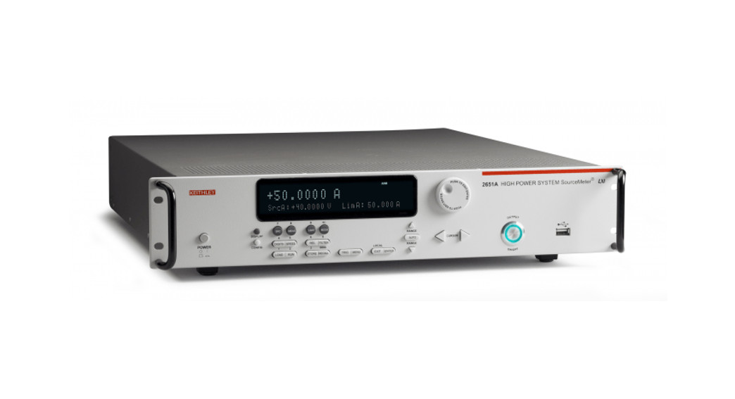
The Model 2657A System SourceMeterTM Instrument is a high-power source measure unit (SMU) that characterizes and tests high voltage electronics. It helps you improve productivity in applications across R&D, reliability, and production testing. It is useful for components and materials characterization where high voltage and precise measurement of voltage and current is required.The documentation for the 2657A includes:
- Quick Start Guide (this document): This shows you how to unpack and set up the instrument and verify that the instrument is functional.
- User’s Manual: Provides a starting point for the creation of applications with a variety of application-based examples.
- Reference Manual: Provides comprehensive information about the features and programming commands of the instrument.
Complete documentation for the 2657A instrument is available for download on the Keithley web page at tek.com/keithley.Software for the 2657A instrument is also available for download from the Keithley web page at tek.com/keithley. You can search for the specific software you need. Available software includes:
- Keithley KickStart Instrument Control Software: This Lets you start making measurements in minutes without complex instrument programming. Free 30-day trial.
- Test Script Builder: This software provides an environment to develop a test program and the ability to load the test program onto the instrument.
- IVI-COM Driver: A IVI instrument driver you can use to create your own test applications in C/C++, VB.NET or C#. It can also be called from other languages that support calling a DLL or ActiveX(COM) object.
- LabVIEWTM Software drivers: Drivers to communicate with National Instruments LabView software.
- Keithley I/O layer: Manages communications between Keithley instrument drivers and software applications and the instrument.
Introduction
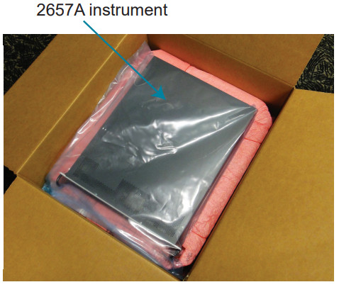
Unpack and inspect the instrumentTo unpack and inspect the instrument:
- Inspect the box for damage.
- Open the top of the box.

- Remove the packaging insert.
- Carefully lift the 2657A instrument out of the box.
- Inspect the instrument for any obvious signs of physical damage. Report any damage to the shipping agent immediately.

 You receive the 2657A with these accessories and documents:
- Rack-mount kit
- Green and yellow ground cable
- Interlock DB-25 male connector kit hardware
- RJ45 LAN crossover cable
- Power line cord
Model 2657A Quick Start Guide (not shown, this document)Safety supplement (not shown)Safety precautions (not shown)Software and documentation downloads document (not shown)
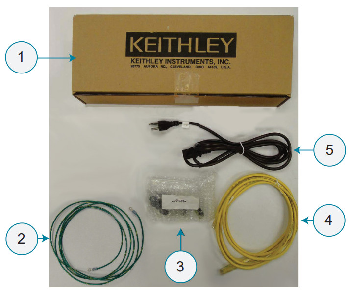 Items shipped may vary from items pictured here.
Unpack
Connect the instrumentImportant test system safety informationThis product is sold as a stand-alone instrument that may become part of a system that could contain hazardous voltages and energy sources. It is the responsibility of the test system designer, integrator, installer, maintenance personnel, and service personnel to make sure the system is safe during use and is operating properly.You must also realize that in many test systems a single fault, such as a software error, may output hazardous signal levels even when the system indicates that there is no hazard present.It is important that you consider the following factors in your system design and use:
- The international safety standard IEC 61010-1 defines voltages as hazardous if they exceed 30 VRMS and 42.4 VPEAK or 60 V dc for equipment rated for dry locations. Keithley Instruments products are only rated for dry locations.
- Read and comply with the specifications of all instruments in the system. The overall allowed signal levels may be constrained by the lowest-rated instrument in the system. For example, if you are using a 500 V power supply with a 300 V dc rated switch, the maximum allowed voltage in the system is 300 V dc.
- Cover the device under test (DUT) to protect the operator from flying debris in the event of a system or DUT failure.
- Make sure any test fixture connected to the system protects the operator from contact with hazardous voltages, hot surfaces, and sharp objects. Use shields, barriers, insulation, and safety interlocks to accomplish this.
- Double-insulate all electrical connections that an operator can touch. Double insulation ensures the operator is still protected even if one insulation layer fails. Refer to IEC 61010-1 for specific requirements.
- Make sure all connections are behind a locked cabinet door or another barrier. This protects the system operator from accidentally removing a connection by hand and exposing hazardous voltages.
- Use high-reliability fail-safe interlock switches to disconnect power sources when a test fixture cover is opened.
- Where possible, use automatic handlers so that operators are not required to access the DUT or other potentially hazardous areas.
- Provide training to all users of the system so that they understand all potential hazards and know how to protect themselves from injury.
- In many systems, during power-up, the outputs may be in an unknown state until they are properly initialized. Make sure the design can tolerate this situation without causing operator injury or hardware damage.
NOTETo keep users safe, always read and follow all safety warnings provided with each of the instruments in your system.
Install the instrumentYou can use the 2657A on a bench or in a rack. See the instructions that came with your rack-mount kit if you are installing the 2657A in a rack.Note that the air intakes for the fan are located on the top cover and side panels of the Model 2657A. The space around these areas should be free from obstruction to ensure proper fan operation.Position the instrument so that it is easy to reach any disconnecting devices, such as the power cord and the power switch.
Connect protective earth (safety ground) to the rear panel of the 2657A.
![]() WARNINGThe ground wire must be attached to known protective earth (safety ground) before powering on the instrument. Failure to attach the ground wire to known protective earth (safety ground) may result in electric shock.
WARNINGThe ground wire must be attached to known protective earth (safety ground) before powering on the instrument. Failure to attach the ground wire to known protective earth (safety ground) may result in electric shock.
Wiring the interlockThe 2657A is a high-voltage instrument that can output hazardous live voltages. It is designed to be used with a test fixture or in a system in which operators are not exposed to such hazardous voltages.The 2657A provides an interlock as a method for ensuring operator safety. The output of the 2657A can only be turned on when the interlock line is enabled. If you attempt to turn on the output when the interlock is disabled, the instrument generates error code 802, “Output blocked by interlock.”
Connect
The interlock line is enabled when it is pulled high through a switch to > +4 V. To drive the interlock pin high, the external supply must supply a minimum of 50 mA. The interlock line is disabled when the signal applied is < +4 V. The absolute maximum input is – 0.4 V to +6.0 V.
The interlock is intended for use through a normally openswitch. This switch may be installed on the lid of a test fixture, the enclosure of a semiconductor prober or device handler, or on the doors of a test equipment rack.
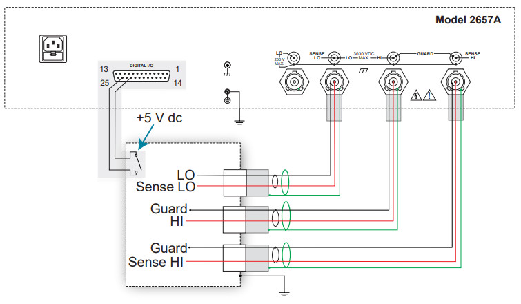
The interlock line is pin 24 of the digital input/output connector on the rear panel of the 2657A, as shown in the following figure.
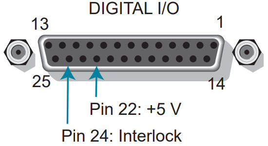
A +5.0 V pin is also available on the digital I/O connector (pin 22). To use the interlock, connect the 5 V pin and the interlock pin to the input and output, respectively, of the switch in your test system.The following graphics show how the interlock is intended to be used with a generic test fixture.
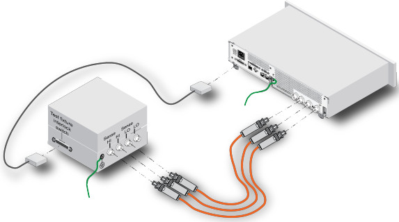
NOTEIf you are using the 2657A with the Model 8010 High Power Device Test Fixture, the interlock connection may be made using the CA-558-2 cable assembly. Refer to the Model 8010 User’s Manual for information on how to connect the 2657Ato the 8010.
If there are multiple points of operator access in the test system, each point should have a separate relay wired in series with the interlock. Using a series connection ensures operator safety if an attempt is made to access the circuit while hazardous voltages are present.
 WARNINGConnect the enclosure of all-metal test fixtures to protective earth (safety ground). Nonconductive test fixtures must be rated to double the maximum voltage in the test circuit. Failure to attach the ground wires to known protective earth may result in electric shock.
WARNINGThe 2657A is provided with an interlock circuit that must be positively activated in order for the high voltage output to be enabled. The interlock helps facilitate the safe operation of the equipment in a test system. Bypassing the interlock could expose the operator to hazardous voltages that could result in personal injury or death.
Connect
Connect line powerThe 2657A operates from a line voltage of 100 V to 240 V at a frequency of 50 Hz or 60 Hz. Make sure the operating voltage in your area is compatible. WARNINGThe power cord supplied with the 2657A contains a separate ground wire for use with grounded outlets. When proper connections are made, the instrument chassis is connected to the power-line ground through the ground wire in the power cord. Failure to use a grounded outlet may result in personal injury or death due to electric shock. WARNINGDo not replace detachable mains supply cords with inadequately rated cords. Failure to use properly rated cords may result in personal injury or death due to electric shock.
CAUTIONOperating the instrument on an incorrect line voltage may cause damage to the instrument, possibly voiding the warranty.
To connect line power:
- Make sure the front-panel power switch is in the off (O) position.
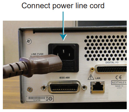
- Connect the socket of the supplied power cord to the power module on the rear panel.
- Connect the plug of the power cord to a grounded ac outlet.
Turn on the instrumentTurn on the instrument by pressing the front-panel POWER switch to the on (|) position.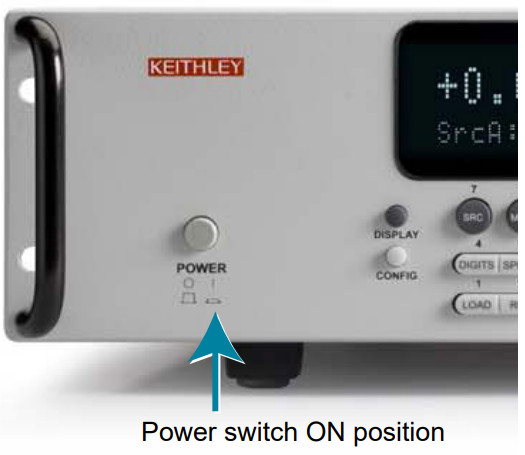 Power-up sequenceWhen the instrument is turned on, you should see:
- A series of dots
- All segments of the display light
- A brief display showing “KEITHLEY Model 2657A”
- Other startup checks
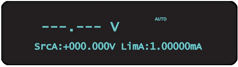
The entire power-up process takes approximately 30 seconds to complete. When initialization is complete, you see the default display screen shown below.
Test
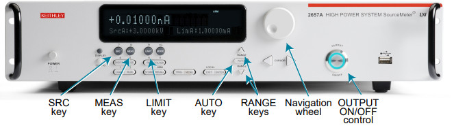
Test the instrumentThe following test verifies the basic operation of the 2657A. In this test, you use the front-panel controls shown below to source voltage and measure the voltage output.NOTEThe following test assumes that the interlock is correctly wired.You do not need to connect a device under test (DUT) for this test.
Step 1: Set source function, range, and level
- Press the SRC key.You will see a blinking character in the SrcA value field. Confirm that the value of volts (V) is displayed; if not, press the SRC key again.
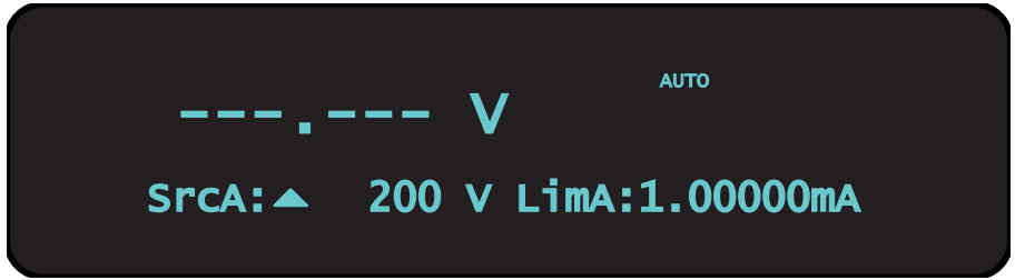
- While that character is still blinking, press the up or down RANGE keys until 200 V is briefly displayed.The main display screen reappears:
- Press the CURSOR keys to move the cursor to the 10s digit.
- Press the navigation wheel keys to move the to enter EDIT mode.The EDIT indicator appears in the upper left corner of the display.
- Turn the navigation wheel to set the source value to 100.0000 V, and then press the navigation wheel to enter the selection and exit EDIT mode.
 The main display screen reappears:
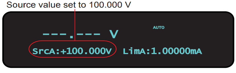
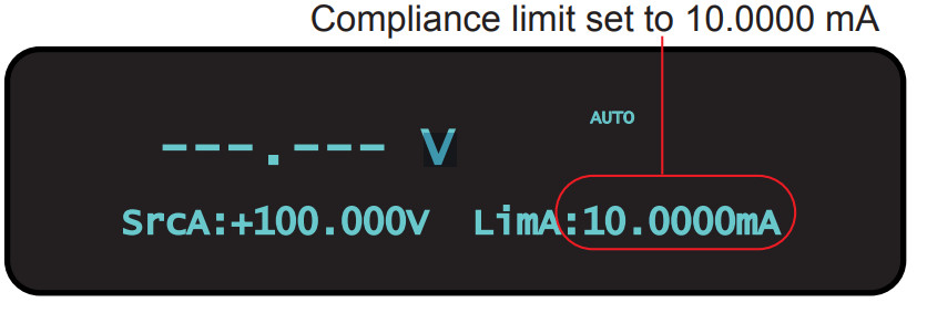
Step 2: Set the compliance limit
- Press the LIMIT key.You will see a blinking character in the LimA value field.
- Press the UP range arrow once so that the 10s digit is displayed. It is displayed as 01.0000mA.
- Use the cursor key to highlight the 1s digit.
- Press the navigation wheel to enter EDIT mode.
- Use the navigation wheel to set the limit to 10 mA.
- Press the navigation wheel again or press ENTER to
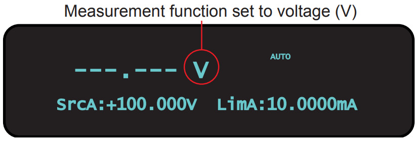
Step 3: Set measurement function and range
- Press the MEAS key as many times as needed to select the V (voltage) measurement function. In the following figure, the measurement function has been set to volts.
Test - Press the key as many times as needed to select the AUTO range function. When AUTO is selected, the 2657A automatically selects the best range for the measured value. You will briefly see the display shown below, and then the main display screen reappears.Step 4: Turn output onTurn the output on by pressing the OUTPUT ON/OFF control. The ON/OFF indicator LED lights and measurements begin.
- Step 5: Observe measurements
- Observe the measured voltage on the main area of front panel display. The readings should be very close to the 100 V source value.
 Test
Test Step 4: Turn output onTurn the output on by pressing the OUTPUT ON/OFF
 Step 6: Turn output offWhen you finish making measurements, turn the output off by pressing the OUTPUT ON/OFF ![]() control. OUTPUT ON/OFF control.The output indicator LED turns off.
control. OUTPUT ON/OFF control.The output indicator LED turns off.
NOTEThese steps confirm the basic functionality of your instrument. Turn the instrument power OFF now.The examples in the Model 2657A User’s Manual demonstrate 2657A functionality. We strongly recommend that first-time users complete the examples in the user’s manual.
FAQsI need a different line frequency or voltage. What should I do?The 2657A requires a line voltage of 100 V ac to 240 V ac (±10%) and a line frequency of either 50 Hz or 60 Hz. Keithley Instruments configures the 2657A to the line frequency appropriate to the final shipping destination of the instrument. This line frequency is used for aperture (NPLC) calculations for integrating analog to digital converter (ADC).You can manually configure the instrument to match the actual line frequency.
To configure the line frequency from the front panel:
- Press the MENU key.
- Turn the navigation wheel to select LINE-FREQ.
- Press the ENTER key.
- Turn the navigation wheel to select the appropriate frequency.
- Press the ENTER key.
- Press the EXIT (LOCAL) key to return to the default display screen.
How do I adapt triaxial connections to coaxial connections for high-voltage applications?Use the optional cable assembly (Keithley Instruments part number SHV-CA-553) that converts a high-voltage triaxial connector to a safe high-voltage (SHV) connector.
What should I do if I get an 802 interlock error?You receive error code 802, “Output blocked by interlock,” if:
- You disable the interlock when the 2657A output is already on
- You attempt to turn on or enable the 2657A output when the interlock is disabled
To recover from this error, properly enable the interlock using a safe test fixture, and then turn on the 2657A output. See “Wiring the interlock” on page 9 for additional information on the interlock.Where can I find updated drivers or firmware?For the latest drivers and additional support information, see the Keithley Instruments support website.To find drivers that are available for your instrument:
- Go to tek.com/product-support.
- Enter 2657A and select Go.
- Select Software.
Next stepsFor more information, refer to the Keithley Instruments website, tek.com/keithley, for support and additional information about the instrument, including the Model 2657AReference Manual, which provides detailed information about all features of the instrument, including descriptions of TSP commands.
Contact information: 1-800-833-9200For additional contacts, see https://www.tek.com/contact-us
Find more valuable resources at TEK.COM.Copyright © 2021, Tektronix. All rights reserved.Tektronix products are covered by U.S. and foreign patents, issued and pending. Information in this publication supersedes that in all previously published material. Specification and price change privileges reserved. TEKTRONIX and TEK are registered trademarks of Tektronix, Inc. All other trade names referenced are the service marks, trademarks, or registered trademarks of their respective companies.
![]()
![]()

References
[xyz-ips snippet=”download-snippet”]