![]()
Model 4299-2 Dual-UnitRack-Mount Kit Installation InstructionsKeithley Instruments28775 Aurora RoadCleveland, Ohio 441391-800-833-9200tek.com/keithley
Introduction
The Model 4299-2 Dual-Unit Rack-Mount Kit contains the hardware required to mount two half-rack instruments in a standard 48.3 cm (19 in.) rack. Typical installation is for two Series 2600A or 2600B System SourceMeter® instruments or one Series 2600A or 2600B instrument with another half-rack instrument.
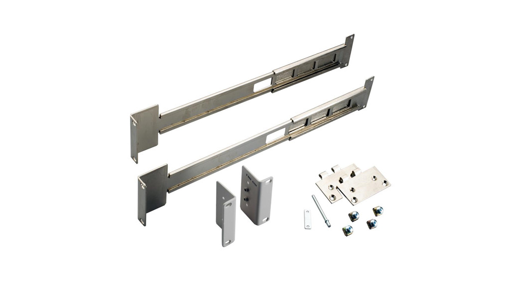
Parts list
Refer to the table below for a list of parts included in the kit.
| Quantity | Description | Keithley part number |
| 2 | Hinge | 2602-328 |
| 2 | Front rack-ear | 2602-355 |
| 2 | Rear rack-mount bracket | 2602-334 |
| 2 | Rack-mount extension arm | 2602-335 |
| 1 | Rear bracket | 2304-327 |
| 1 | Quick-release pin | FA-352 |
| 8 | Cage nut | FA-274 |
| 2 | #6 Lock washer | 6LKWA |
| 2 | Washer | WA-81 |
| 4 | #8-32 x 3/8 in. Phillips pan-head screw | 8-32×3/8PPH |
| 4 | #8-32 x 3/8 in. Phillips flat-head screw | 8-32×3/8PFH |
| 4 | #10-32 x 3/8 in. Phillips pan-head SEMS screw | 10-32×3/8PPHSEM |
| 8 | #10-32 x 5/8 in. Phillips truss-head screw | 10-32×5/8PHTRSH |
| 2 | #6-32 x 5/8 in. Phillips pan-head screw | 6-32×5/8PPH |
| 2 | M4 x 12 mm Phillips pan-head screw | M4 x12PPH |
| 2 | M4 x 12 mm Phillips flat-head screw | M4 x12MMPFH |
Tools required
- Medium (#2) Phillips screwdriver
- 3/8-inch wrench
- Flat-bladed screwdriver or cage-nut installation tool
 PPA-909J
 WARNINGTurn off instrument power and unplug all cables before installing an instrument in a rack.Failure to remove power before installation may cause personal injury or death from electrical shock.
CAUTIONHeat sources should be mounted away from the instrument, cabling, and accessories, with sufficient space provided between the instrument and heat source for airflow and cooling.
NOTETo prevent damaging heat build-up and ensure specified performance, make sure there is adequate ventilation and airflow around the instrument to ensure proper cooling. Do not cover the ventilation holes on the sides or back of the instrument. The rear vents and both side vents must be unobstructed to properly dissipate heat.Mount precision equipment as low as possible in the rack. Operating temperatures are cooler lower in the rack.
Prepare the instrument
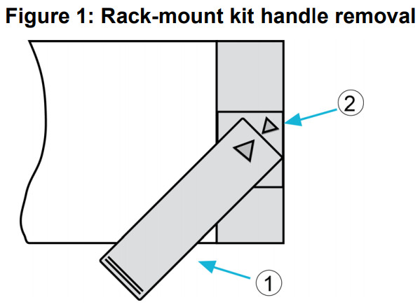
To remove the handle, mounting ears, and rear feet:
- Gently pull the handle (1) away from the sides of the instrument case and swing it up or down until the orientation arrows on the handles line up with the orientation arrows on the mounting ears, as shown in the following figure.

- After you align the arrows (2), pull the ends of the handle (1) away from the case.
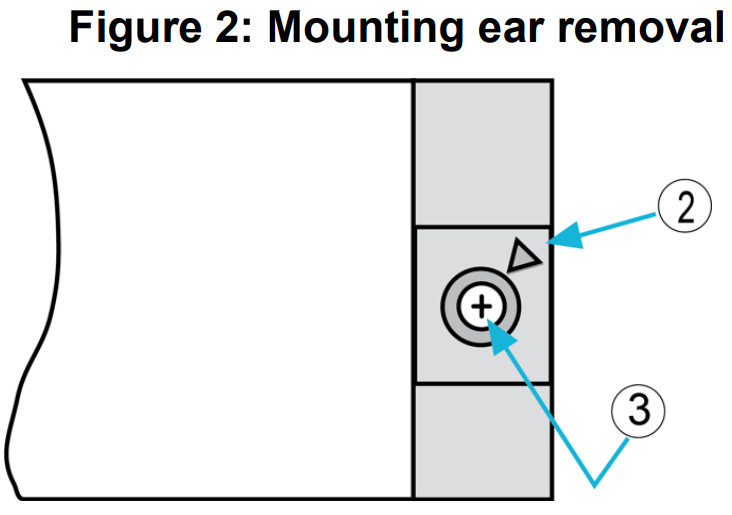
- Remove the screw that secures each mounting ear (3).
- Pull down and out to remove each ear.
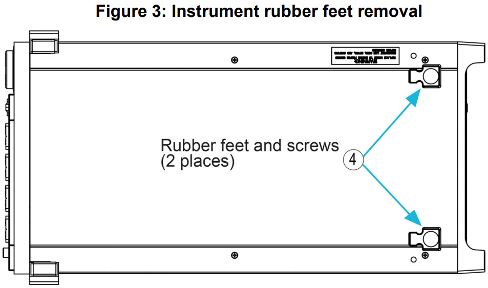
- From the bottom of the instrument, pull out the rubber feet and remove the screws (4), see the following figure.
- Store the handle, rubber feet, and hardware for future use.
Install mounting hardware
Install the mounting hardware on the opposite sides of each instrument, as shown in the following figures.To install the mounting hardware on the instruments:
- Place the instruments side-by-side, in the same position that they will be installed in the rack.
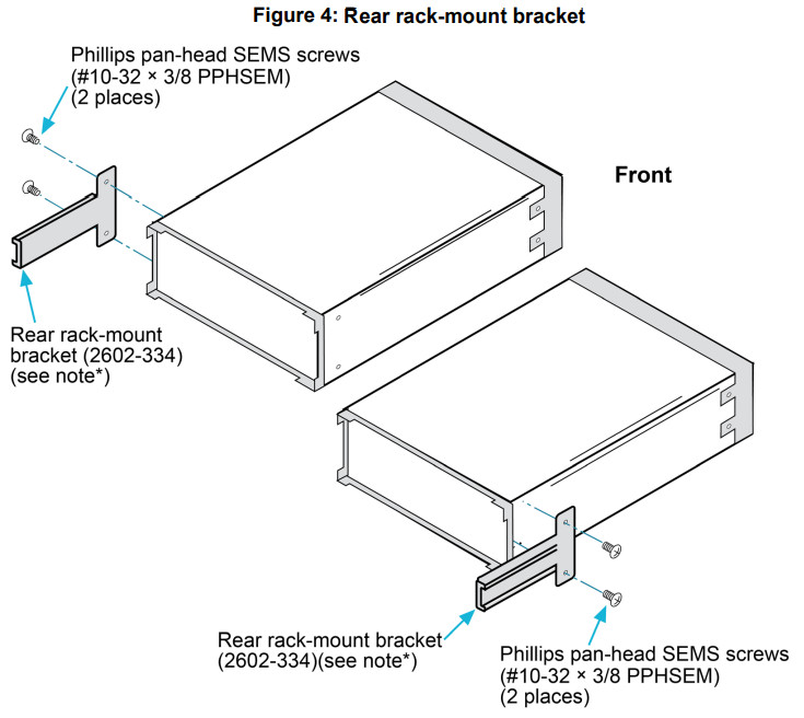
- Secure one rear rack-mount bracket (2602-334) to each instrument on the selected side using two Phillips pan-head SEMS screws (#10-32 × 3/8 PPHSEM).NOTEIf the two instruments are not the same length, do not use one of the rear rack-mount brackets. Refer to Install the instruments (on page 9), “To install two instruments that are of unequal length” for more detail. Additionally, save all unused parts for future use.
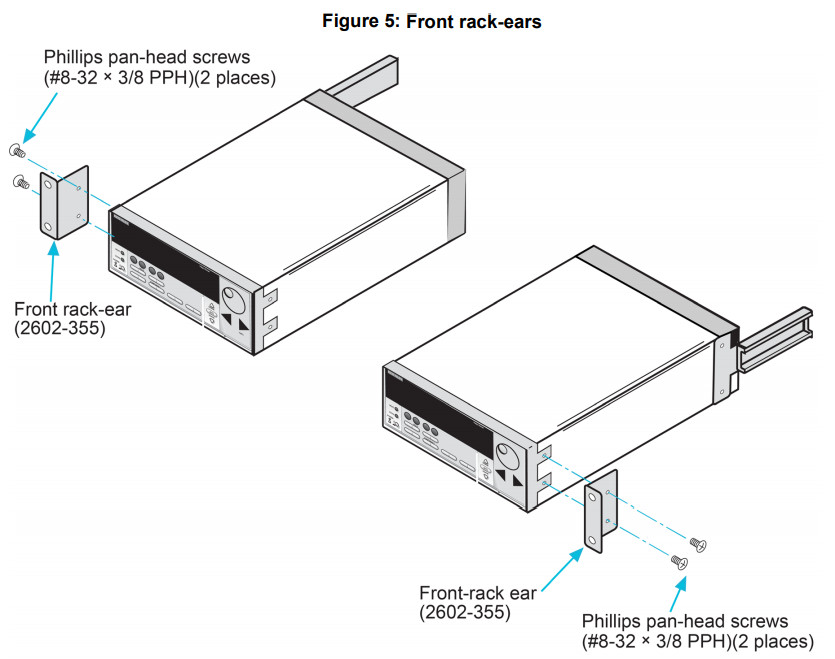
- Attach the front rack-ear (2602-355) to the outside of each instrument using two Phillips pan-head screws (#8-32 × 3/8 PPH) on the same side as the rear rack-mount bracket (2602-334).
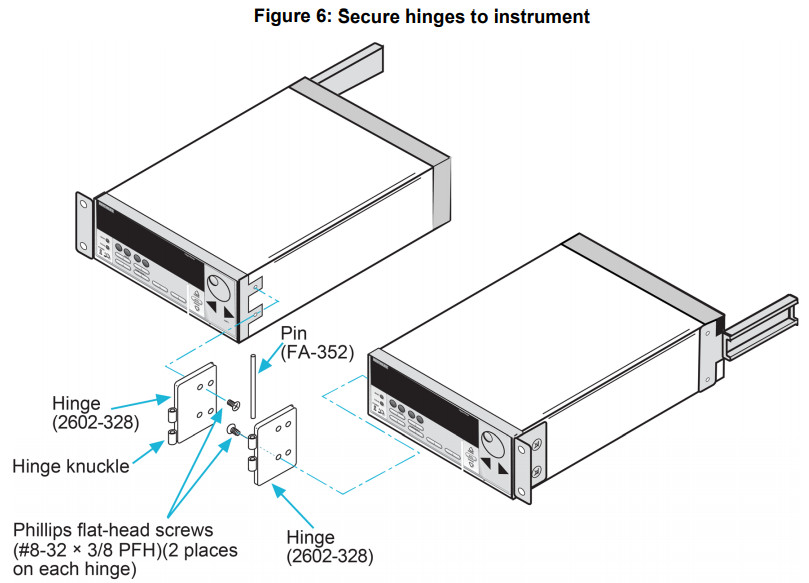
- Secure a hinge (2602-328) to both instruments using two Phillips flat-head screws (#8-32 × 3/8 PFH) oneach, make sure the knuckle of the hinge is facing the front of the instrument, as shown in the following figure.
- Insert the quick-release pin (FA-352) in the hinge knuckle to assemble the hinge.
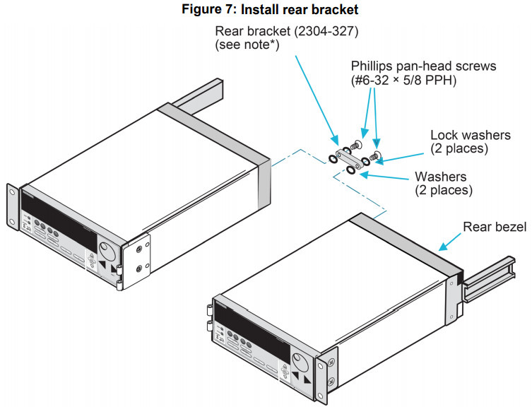
If the two Keithley Instruments are the same depth, you can install the rear bracket onto the rear bezels. To do this:
- Remove one rear bezel screw from each instrument. Do not completely remove the rear bezel.
- Install the rear bracket (2304-327) and secure it and the applicable rear bezels with two Phillips pan-head screws (#6-32 × 5/8 PPH), washers (WA-81), and lock washers (6LKWA).*Rear bracket used only with Keithley Instruments products of the same length
Prepare the rack
 Prepare the rack
To prepare the rack for installation:
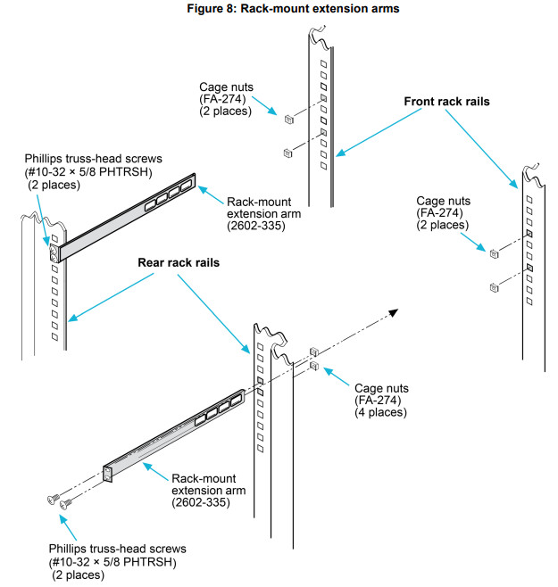
- Install the cage nuts (FA-274) into the rack holes to be aligned with the holes in the rack-mount extension arms (2602-335). The rack holes selected determine the placement of the instrument in the rack (see the following figure).
- Install one rack-mount extension arm onto one of the rear rack rails and secure it using two Phillips truss head screws (#10-32 × 5/8 PHTRSH).NOTECage nuts for the front rack-ear and rack-mount extension arm should be installed into the rails at the same hole spacing (vertical height).NOTEIf the two instruments are not the same length, do not use one of the rack-mount extension arms.Refer to Install the instruments (on page 9), “To install two instruments that are of unequal length” for more detail.
- Repeat the procedure on the other side.
- Install cage nuts into the front rack rail holes aligned with the rear cage nuts.
- Save all unused parts for future use.
Install the instruments
When rack mounting restricts access to the main power cord, provide a separate main power disconnect device, located close to the equipment and within easy reach of the operator.
WARNINGFailure to disconnect all power when needed may expose personnel to hazardous voltages, which, if contacted, could cause personal injury or death.
NOTETo complete this procedure, two people are recommended.To install the instruments:
- Slide the instruments into the rack by aligning both rear rack-mount brackets (2602-334) with the rackmount extension arms, as shown in the following figure.
- While supporting the instruments, secure them to the front rack rails with four Phillips truss-head screws (#10-32 × 5/8 PHTRSH).
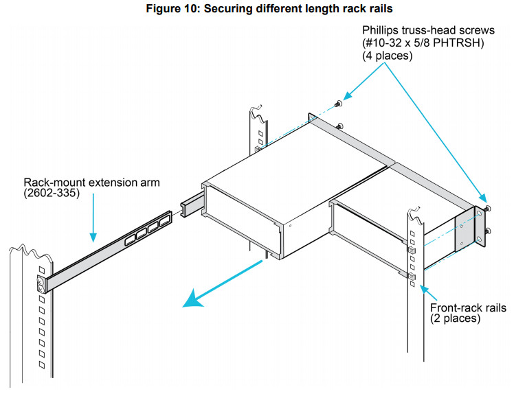
To install two instruments that are of unequal length:
- Slide the instruments into the rack by aligning the instrument, rear rack-mount bracket (2602-334), and the rack-mount extension arm (2602-335), also align the front rack rail for the other instrument, as shown in the following figure.
- While supporting the instruments, secure them to the front rack rails with four Phillips truss-head screws ( #10-32 × 5/8 HARSH).
Safety precautions
The following safety precautions should be observed before using this product and any associated instrumentation. Although some instruments and accessories would normally be used with nonhazardous voltages, there are situations where hazardous conditions may be present.This product is intended for use by personnel who recognize shock hazards and are familiar with the safety precautions required to avoid possible injury. Read and follow all installation, operation, and maintenance information carefully before using the product. Refer to the user documentation for complete product specifications.If the product is used in a manner not specified, the protection provided by the product warranty may be impaired.The types of product users are:The responsible body is the individual or group responsible for the use and maintenance of equipment, for ensuring that the equipment is operated within its specifications and operating limits, and for ensuring that operators are adequately trained.Operators use the product for its intended function. They must be trained in electrical safety procedures and proper use of the instrument. They must be protected from electric shock and contact with hazardous live circuits.Maintenance personnel performs routine procedures on the product to keep it operating properly, for example, setting the line voltage or replacing consumable materials. Maintenance procedures are described in the user documentation. The procedures explicitly state if the operator may perform them. Otherwise, they should be performed only by service personnel.Service personnel are trained to work on live circuits, perform safe installations, and repair products. Only properly trained service personnel may perform installation and service procedures.Keithley products are designed for use with electrical signals that are measurement, control, and data I/O connections, with low transient overvoltages, and must not be directly connected to mains voltage or to voltage sources with high transient overvoltages. Measurement Category II (as referenced in IEC 60664) connections require protection for high transient overvoltages often associated with local AC mains connections. Certain Keithley measuring instruments may be connected to mains. These instruments will be marked as category II or higher.Unless explicitly allowed in the specifications, operating manual, and instrument labels, do not connect any instrument to mains.Exercise extreme caution when a shock hazard is present. Lethal voltage may be present on cable connector jacks or test fixtures. The American National Standards Institute (ANSI) states that a shock hazard exists when voltage levels greater than 30 V RMS, 42.4 V peak, or 60 VDC are present. A good safety practice is to expect that hazardous voltage is present in any unknown circuit before measuring.Operators of this product must be protected from electric shock at all times. The responsible body must ensure that operators are prevented access and/or insulated from every connection point. In some cases, connections must be exposed to potential human contact. Product operators in these circumstances must be trained to protect themselves from the risk of electric shock. If the circuit is capable of operating at or above 1000 V, no conductive part of the circuit may be exposed.For maximum safety, do not touch the product, test cables, or any other instruments while power is applied to the circuit under test. ALWAYS remove power from the entire test system and discharge any capacitors before: connecting or disconnecting cables or jumpers, installing or removing switching cards, or making internal changes, such as installing or removing jumpers.Do not touch any object that could provide a current path to the common side of the circuit under test or power line (earth) ground. Always make measurements with dry hands while standing on a dry, insulated surface capable of withstanding the voltage being measured.For safety, instruments and accessories must be used in accordance with the operating instructions. If the instruments or accessories are used in a manner not specified in the operating instructions, the protection provided by the equipment may be impaired.Do not exceed the maximum signal levels of the instruments and accessories. Maximum signal levels are defined in the specifications and operating information and shown on the instrument panels, test fixture panels, and switching cards.Chassis connections must only be used as shield connections for measuring circuits, NOT as protective earth (safety ground) connections.The WARNING heading in the user documentation explains hazards that might result in personal injury or death. Always read the associated information very carefully before performing the indicated procedure.The CAUTION heading in the user documentation explains hazards that could damage the instrument. Such damage may invalidate the warranty.The CAUTION heading with the ![]() symbol in the user documentation explains hazards that could result in moderate or minor injury or damage to the instrument. Always read the associated information very carefully before performing the indicated procedure. Damage to the instrument may invalidate the warranty.Instrumentation and accessories shall not be connected to humans.Before performing any maintenance, disconnect the line cord and all test cables.To maintain protection from electric shock and fire, replacement components in mains circuits — including the power transformer, test leads, and input jacks — must be purchased from Keithley. Standard fuses with applicable national safety approvals may be used if the rating and type are the same. The detachable mains power cord provided with the instrument may only be replaced with a similarly rated power cord. Other components that are not safety-related may be purchased from other suppliers as long as they are equivalent to the original component (note that selected parts should be purchased only through Keithley to maintain the accuracy and functionality of the product). If you are unsure about the applicability of a replacement component, call a Keithley office for information.Unless otherwise noted in product-specific literature, Keithley instruments are designed to operate indoors only, in the following environment: Altitude at or below 2,000 m (6,562 ft); temperature 0 °C to 50 °C (32 °F to 122 °F); and pollution degree 1 or 2. To clean an instrument, use a cloth dampened with deionized water or mild, water-based cleaner. Clean the exterior of the instrument only. Do not apply cleaner directly to the instrument or allow liquids to enter or spill on the instrument. Products that consist of a circuit board with no case or chassis (e.g., a data acquisition board for installation into a computer) should neverrequire cleaning if handled according to instructions. If the board becomes contaminated and operation is affected, the board should be returned to the factory for proper cleaning/servicing.Safety precaution revision as of June 2017.
symbol in the user documentation explains hazards that could result in moderate or minor injury or damage to the instrument. Always read the associated information very carefully before performing the indicated procedure. Damage to the instrument may invalidate the warranty.Instrumentation and accessories shall not be connected to humans.Before performing any maintenance, disconnect the line cord and all test cables.To maintain protection from electric shock and fire, replacement components in mains circuits — including the power transformer, test leads, and input jacks — must be purchased from Keithley. Standard fuses with applicable national safety approvals may be used if the rating and type are the same. The detachable mains power cord provided with the instrument may only be replaced with a similarly rated power cord. Other components that are not safety-related may be purchased from other suppliers as long as they are equivalent to the original component (note that selected parts should be purchased only through Keithley to maintain the accuracy and functionality of the product). If you are unsure about the applicability of a replacement component, call a Keithley office for information.Unless otherwise noted in product-specific literature, Keithley instruments are designed to operate indoors only, in the following environment: Altitude at or below 2,000 m (6,562 ft); temperature 0 °C to 50 °C (32 °F to 122 °F); and pollution degree 1 or 2. To clean an instrument, use a cloth dampened with deionized water or mild, water-based cleaner. Clean the exterior of the instrument only. Do not apply cleaner directly to the instrument or allow liquids to enter or spill on the instrument. Products that consist of a circuit board with no case or chassis (e.g., a data acquisition board for installation into a computer) should neverrequire cleaning if handled according to instructions. If the board becomes contaminated and operation is affected, the board should be returned to the factory for proper cleaning/servicing.Safety precaution revision as of June 2017.
PA-909 Rev. J April 2021
References
[xyz-ips snippet=”download-snippet”]