
SMU Potentiostats and EC-UPGRADE KitQuick Start Guide
Description
The Keithley Instruments SMU (source-measure unit) Potentiostats are designed to make electrochemicalmeasurements easily and accurately. Included with your Model 2450, 2460, or 2461 Interactive SourceMeter™ Instrument and other hardware is a USB flash drive containing electrochemistry test scripts or applications.When running, each application can be user-configured to meet your specific test requirements.The EC-UPGRADE kit lets you use an existing Keithley Instruments 2450, 2460, or 2461 SourceMeter as a potentiostat or galvanostat.The following applications are installed on your instrument or on the supplied USB flash drive.
- Cyclic Voltammetry: Potential is swept at a user-programmable scan rate between two to four defined potential vertices, and the resulting current is measured.
- Open Circuit Potential: Measures the cell potential difference between two electrodes with high-input impedance as a function of time.
- Potential Pulse and Square Wave: Sources potential at programmable peak and base levels while current are recorded at the pulse peak level, and the resulting current is measured.
- Current Pulse and Square Wave: Sources current at programmable peak and base levels, and the potential is recorded at the pulse peak level.
- Chronoamperometry: Potential is stepped to a programmed value, and the resulting current is measured as a function of time.
- Chronopotentiometry: Current is stepped to a programmed value, and the resulting potential is measured as a function of time.
WARNING
This kit is not intended to be used with an SMU interlock enabled. To prevent electric shock and possible damage to the test cable assembly or test setup, do not activate the Keithley Instruments 2450, 2460, or 2461 interlock.When the interlock is not engaged on 2450, 2460, or 2461 the nominal output is limited to ±42 V. However, review the Safety Precautions (on page 23) section of this document to ensure responsible operation.
What you should have received
Below is a list of what you should have received. If you only ordered the EC-UPGRADE kit, an SMU instrument is not included.
|
Model number |
Description |
Quantity |
| 2450, 2460, or 2461 | Keithley Instruments 2450, 2460, or 2461 Interactive SourceMeter SMU Instrument with power cable | 1 |
| 01217440x | 1 m connectorized cable assembly | 1 |
| 013042100 | Insulated miniature alligator clips | 4 |
| 2450-800x | Interactive Sourcemeter Electrochemistry Kit USB Flash Drive and Instructions (not pictured) | 1 |
Figure 1: EC-UPGRADE kit shipping contents
Getting started
Before you can run an electrochemistry test, you will need to configure the instrument and make basic connections. The following topics will explain how to set up and configure your instrument.
NOTEThe 2450-EC or 2460-EC instrument must have firmware version 1.5.0 or later to run the electrochemistry test applications. The 2461-EC must have firmware version 1.6.0 or later.Scripts with version numbers lower than 189427 are compatible with firmware versions 1.5.0 (1.6.0 for 2461) to 1.6.7. Scripts with version numbers of 189427 and higher are compatible with firmware versions 1.5.0 (1.6.0 for 2461) to 1.6.7 and version 1.7.2 and higher. The script version number is displayed near the top right corner of an application’s Home screen.To view the firmware version, press the MENU key, then select Info/Manage under System.The firmware version is at the upper-left of your display. The latest firmware is available from the Keithley Instruments website (tek.com/keithley).
Power the instrument on or off Follow the steps below to connect the SMU to line power and turn on the instrument. The SMU operates from a line voltage of 100 V to 240 V at a frequency of 50 Hz or 60 Hz. It automatically senses line voltage and frequency. Make sure the operating voltage in your area is compatible.You must turn on the SMU and allow it to warm up for at least one hour to achieve rated accuracies.
CAUTIONOperating the instrument on an incorrect line voltage may cause damage to the instrument, possibly voiding the warranty.
WARNING
The power cord supplied with the 2450-EC, 2460-EC, and 2461-EC contains a separate protective earth (safety ground) wire for use with grounded outlets. When proper connections are made, the instrument chassis is connected to the power-line ground through the ground wire in the power cord. In addition, a redundant protective earth connection is provided through a screw on the rear panel. This terminal should be connected to known protective earth. In the event of a failure, not using a properly grounded protective earth and grounded outlet may result in personal injury or death due to electric shock.Do not replace detachable mains supply cords with inadequately rated cords. Failure to use properly rated cords may result in personal injury or death due to electric shock.
To connect the power cord:
- Make sure that the front-panel POWER switch is in the off (O) position.
- Connect the female end of the supplied power cord to the AC receptacle on the rear panel.
- Connect the male end of the power cord to a grounded AC outlet.
To turn the instrument on or off:
- Before turning the instrument on, disconnect any devices under test (DUTs) from the instrument.
- To turn your instrument on, press the front-panel POWER switch to place it in the on (|) position. The instrument displays a status bar as it powers on. The home screen is displayed when the power on is complete.
- To turn your instrument off, press the front-panel POWER switch to place it in the off (O) position.
NOTEOn some sensitive or easily damaged devices under test (DUTs), the instrument power-up and power-down sequence can apply transient signals to the DUT that may affect or damage it. When testing this type of DUT, do not make final connections to it until the instrument has completed its power-up sequence and is in a known operating state. When testing this type of DUT, disconnect it from the instrument before turning the instrument off.To prevent any human contact with a live conductor, connections to the DUT must be fully insulated and the final connections to the DUT must only use safety-rated safety jack socket connectors that do not allow bodily contact.
Select the high-impedance, output-off state
Before making physical connections from the instrument to the test cell, set the output of the instrument to the high-impedance, output-off state. When the high-impedance output-off state is selected, the output relay opens, disconnecting the instrument from the load.To set the output of your SMU to the high-impedance output-off state:
- Press the MENU key.
- Under Source, select Settings.
- Select Output Off.
- Choose High Z (high impedance).
NOTEYou may receive a notification about making measurements with the output turned off. Select OK to clear the message or select Details to see more information.
Copy a script to the instrument
Your SMU is shipped with all test applications and supporting scripts loaded into memory.
NOTEIf you accidentally delete a test application or a supporting script (EC_Framework.tsp or EC_Images.tsp), you can copy the files from the flash drive to your instrument.
If you are upgrading your SMU with the EC-UPGRADE kit, you can run the test applications from the flash drive or copy the files from the flash drive to the instrument. If you choose to copy the applications, you must also copy the support files (EC_Framework.tsp and EC_Images.tsp) to your SMU.
To copy a script to the SMU:
- Insert the USB flash drive into the USB port on the front panel.
- Press the MENU key.
- Under Scripts, select Manage. The Manage Scripts menu opens. Your list of Internal Scripts may appear different than the following figure.
- In the USB Scripts list, select the test script you want to copy to the SMU. For this example, you will copy the cyclic voltammetry test script.

- Select <. The test script is transferred to the instrument, and the corresponding filename is displayed in the Internal Scripts list.


Connections and usage
The cable assembly can be used with Keithley SMUs for electrochemistry applications. Each connector of the assembly is labeled according to its function:
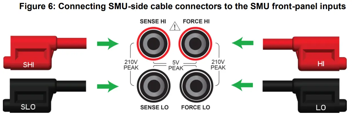
Make the SMU connections
To connect to the instrument (all tests):The front panel of your SMU has four banana-style input and output jacks. You use the supplied cable to connect your electrochemical cell to these jacks.The SENSE terminals are used to measure the voltage at the device under test (DUT). When you use sense leads, the voltage drop across the force leads is eliminated from a measurement. This produces more accurate voltage sourcing and measurement at the DUT. Plug the SHI and SLO connectors into the SENSE terminals.The FORCE terminals are used to source or sink voltage or current to or from a DUT. Plug the HI and LO connectors into the FORCE terminals.Plug the four SMU-side cable connectors into the front of your SMU instrument as shown in the below graphic.
Make the device connections
The test cable lets you make connections to test cells with two, three, or four electrodes.For two-electrode applications, the device-side cable connectors are used in stacked pairs. Connect the WE and WES pair to the working electrode of your electrochemical cell, and connect the CE and RE pair to the counter electrode of the cell.
For three-electrode applications, the WE and WES connectors are stacked and attached to the working electrode. The CE and RE connectors connect to the counter electrode and reference electrode, respectively.
For four-electrode applications, each device-side cable connector is used separately.

Attach the alligator clips
Four insulated alligator clips are supplied. You can attach these clips to the ends of the device-side connectors,as shown in the following graphic. The clips provide a safe, secure way to connect to your device.
Figure 10: Alligator clip attached to the accessory cable connector

For small cells and electrodes, you can use commercially available banana-to-microchip connectors by plugging them directly into the cable connectors.Once the appropriate connectors or clips are attached, you are ready to connect to the test cell.
Prepare the analyte and assemble the test cellBefore connecting to the DUT, make sure to prepare the analyte and assemble the test cell for your test.
Connect to the DUT
The next figure shows the connections from an SMU to a three-electrode test cell.
Run a test
Once you have configured your SMU and connected a test cell, you are ready to run a test. For this example, you will run the Cyclic Voltammetry test.To run a test:
- Press the HOME key.
- Select the active script indicator at the top of your home screen. If there is no script activity, the indicator displays “No Script.”
- Select the preloaded Cyclic Voltammetry test script or connect the supplied USB drive to your SMU instrument to locate the included Cyclic Voltammetry test. If you connect the USB drive, scripts on the drive are displayed with usb1/ before the script file name, which includes the .tsp file extension.
- Select CyclicVoltammetry. The test application runs and the Cyclic Voltammetry home screen is displayed.
Review the test home screen controlsAll test home screen controls include:
| End App | Select this control to immediately stop the test and return to normal SMU operation. |
| Autoscale | Select this control to define the graph-based upon the plotted data. This is useful for constraining all of the data to the screen’s viewing size. |
| Start Test | Select this control to immediately begin the test. This option becomes Stop Test when the test runs. |
| Save Data | Select this control to save the test data to a . CSV file on a flash drive. This option is only visible after the test runs. |
| Cursor | Select this control to cycle through the available cursor placements: None, Vertical, Horizontal, and Both. |
Define the potential scan parameters
You will define the potential scan parameters: Number of vertices, vertex potentials, potential reference, scan rate, and a number of cycles.An example of a potential scan performed during a cyclic voltammetry test is shown in the next figure.You can select up to four voltage potential vertices, which are defined as E1 (or E initial), E2, E3, and E4 in the next figure. The slope of the lines is determined by the scan rate that you use. You will set the scan rate later in this step of the test.
Figure 15: Potential sweep versus time of cyclic voltammetry example
For this step, you will set the Number of vertices, define their potentials, and specify the potential reference.
To select the Number of Vertices:
- Press the MENU key, then select Scan Settings.
- Select Number of Vertices.
- Enter the number of potential vertices. You can define two, three, or four vertices.
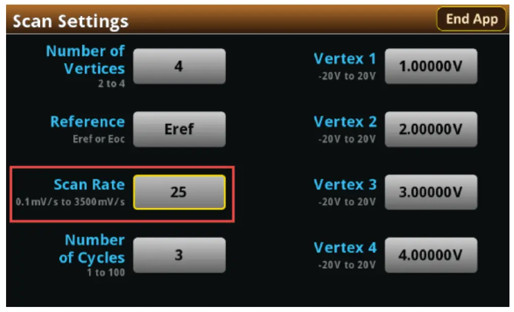
- The vertex selections will change based on the number of vertices you choose. Select each vertex to enter its potential. For this example, you will define four vertices.Figure 17: Scan Settings menu, defining four vertices
- Enter each vertex value in the range of ±20 V.
After you define the vertices, select the potential reference: Eref or Eoc. If you select Eref, the applied potential is relative to the potential at the reference electrode. If you select Eoc, the applied potential is relative to the open-circuit potential of the cell (EOC), which is measured immediately before the scan begins.
To select the potential reference:
- From the Scan Settings menu, select Reference.Figure 18: Scan Settings menu, selecting Reference
- Select Eref or Eoc.
Define the scan settings
You can specify the scan rate in units of millivolts per second. The scan rate, defined as the change of the potential as a function of time (∆E/∆t), determines the rate at which the potential is linearly scanned during the experiment. You can select a scan rate of 0.1 mV per second to 3500 mV per second.To select the scan rate:
- From the scan Settings menu, select Scan RateFigure 19: Scan Settings menu, selecting Scan Rate
- Enter a value.
- Select OK.
After entering the scan rate, you will choose the number of cycles, from 1 to 100. The number of cycles determines how many times each scan is repeated.
To select the number of scan cycles:
- From the Scan Settings screen, select Number of Cycles.Figure 20: Scan Settings menu, selecting the Number of Cycles
- Enter a value.
- Select OK.
The following figure shows an example of potential versus time graph showing three cycles of a three-vertex voltage sweep.
Figure 21: Example potential versus time graph
Modify the measure settings
Specify how often to make measurements during the scan by selecting one of the sampling rate units shown in the following table and setting a value for the sampling rate. The acquired measurements are stored in the active buffer of the instrument, cvBuffer. The buffer can hold a maximum of 100,000 readings.The following table describes the available interval units and accompanying range of values.
| Sampling rate unit | Description | Sampling rate range of values |
| points/test | The number of points acquired during a test, regardless of how many cycles | 10 to 10,000 |
| points/cycle | The number of points acquired in each cycle | 10 to 10,000 |
| s/point | The number of seconds per each point | 0.01 to 100 |
| points/s | The number of points taken per second | 0.01 to 100 |
To select the sampling rate units:
- From the Menu screen, select Measure Settings.
- Select Sampling Rate Units.Figure 22: Measure Settings menu, selecting Sampling Rate Units
- Select the units you want to use for the test. You can now set a sampling rate.
To set the sampling rate:
- From the Measure Settings screen, select Sampling Rate.
- Enter a value.
- Select OK.
Now you will select the current range to measure the current from the scan. Choose the range based upon the largest current magnitude you expect during the test.
To select the current measurement range:
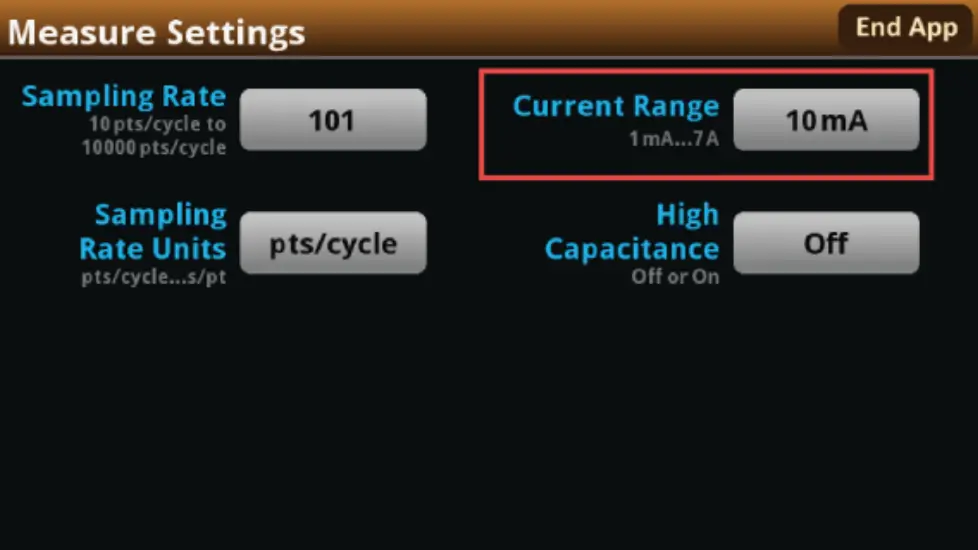
- From the Measure Settings screen, select Current Range.Figure 23: Measure Settings menu, selecting Current RangeNOTEWhen the test runs, your potentiostat will limit the magnitude of the maximum current that can flow in the test circuit to 100 percent of the selected current range. This could affect your experiment results.If your expected current is near the full scale of a range, select the next highest current range to minimize the influence of your potentiostat on the test.
- Choose a value. Note that the choices are different depending on your potentiostat model.Figure 24: Selecting the current range
Although rare, you may encounter overshoot, ringing, or other instability on the output of your SMU potentiostat depending the electrical impedance of your chemical cell. This is particularly an issue when the impedance is capacitive and you are forcing voltage and measuring relatively low currents, as with the cyclic voltammetry test.In these cases, you can use the high-capacitance mode to minimize overshoot, ringing, and instability. See your 24XX Interactive SourceMeter™Reference Manual for more information.
To select the high-capacitance mode:
- From the Menu screen, select Measure Settings.
- Select High Capacitance.Figure 25: High Capacitance Mode selection
- Select Off or On.
Save or load the test parameter data
You can save your test parameters to the front-panel flash drive at any time. Up to five test parameter configurations can be stored.To save the test parameters:
- From the Menu screen, select Save Settings.NOTEIf you have saved a settings file previously with the same File Selection number, you will be prompted to overwrite it.Figure 26: Selecting Save Settings
- Select a file number and then select Save Settings. You are notified when the save is complete, as shown in the next figure. Select OK to clear the prompt.Figure 27: Successful file save

To load saved test parameters:
NOTETest parameters can only be loaded to the same instrument model on which they were created and saved. For example, you cannot load test parameter settings created with a 2450-EC to a 2460-EC.
- From the Menu screen, select Load Settings.Figure 28: Selecting Load Settings
- Select a file by choosing File Selection and then a file number.Figure 29: Choosing a file to load
- Select Load Settings. You are notified when the load completes. Select OK to clear the prompt.
Run the test and view the graph
To run the test and view the graph:
- Press the HOME key.
- Select Start Test. The output turns on automatically, and the display shows the current measurements plotting in real-time, along with a progress bar at the bottom of the screen. The Start Test control also changes to Stop Test for the duration of the test.
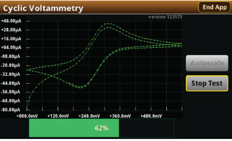
The output turns off when the test completes. The following graphic shows the test home screen during the test. You can return to this home screen at any time when the test is running by selecting the Run / Graph option from the menu screen.
Figure 30: Cyclic voltammetry test results graph
NOTEYou can use the touchscreen to manipulate the graph or add cursors. See your Interactive SourceMeter™Instrument Reference Manual for more information.
You can save a screen capture to a flash drive inserted into the USB port of the potentiostat by simultaneously pressing the HOME key and the ENTER key. The filename has the format imgmmdd_hhmmss.png, where hhmmss represents the instrument hour (in 24-hour notation), month, and day.
NOTETo end the test before the run completes, select Stop Test at any time. This stops the test and turns off the potentiostat output. You can then select End App to exit the test and return to normal SMU operation. If there is a long interval between consecutive samples, there may be a long delay between selecting Stop Test and when the test stops, as the current operation must complete.
WARNING
Make sure to select Stop Test before selecting End App. Stop Test turns off the instrument’s output.Hazardous voltages may be present on all output and guard terminals. To prevent electrical shock that could cause injury or death, never make or break connections to the instrument while the power is turned on. Turn off the equipment from the front panel or disconnect the main power cord from the rear of the instrument before handling cables. Putting the equipment into an output-off state does not guarantee that the outputs are powered off if a hardware or software fault occurs.
Acquire the open-circuit potential (Eoc)
If you selected Eoc as the potential reference for the scan, then the open-circuit potential will be measured immediately after starting the test. You are prompted by the test application, as shown in the next figure.Figure 31: Prompt for Eoc measurement
If you select Yes, the instrument measures the open-circuit potential (Eoc) of your electrochemical cell. If you select No, the test stops. After the Eoc is measured, the value is displayed in a prompt, as shown in the next figure.Figure 32: Eoc measurement displayed
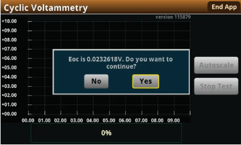
If this value is acceptable, then select Yes to start the scan. If you select No, the test will stop. The measured Eoc value is saved in the eocBuffer internal buffer of the instrument.
View the test reading table
You can view the individual data points by selecting Reading Table from the Menu screen. See the next figure.Figure 33: Viewing the Reading Table

Save the test data to the flash drive
You can save the data generated from the test to the front-panel flash drive. The data is stored in a .csv file that also includes instrument information and parameter settings.If there are more than 10,000 measurements stored, the process of saving the data may take several minutes.
To save the test data to the flash drive:
- Make sure your flash drive is inserted into the front-panel USB port.
- From the test application home screen, select Save Data.
- Specify a file name, then select OK.
- Select OK on the confirmation message.
Figure 34: Test results saved successfully
View the results saved to the flash driveTo view the test results, open the saved file in a spreadsheet program on a computer. Current, voltage, time, and general parameters for the test are included in the file.
End the test applicationWhen you are finished making measurements, select End App to exit the test and return to normal SMU operation.
CAUTIONMake sure to always select Stop Test before selecting End App. Stop Test turns off the instrument’s output.
Next steps
See the Model 2450-EC, 2460-EC, and 2461-EC Potentiostats User’s Guide (document number 07711040x) for detailed information on running the other test scripts included with your potentiostat or upgrade kit. The guide is included on the supplied USB flash drive.Additionally, see your Keithley Instruments 2450, 2460, or 2461 Interactive SourceMeter Instrument ReferenceManual for further details on using your SMU and running a test.
Safety precautions
The following safety precautions should be observed before using this product and any associated instrumentation. Although some instruments and accessories would normally be used with nonhazardous voltages, there are situations where hazardous conditions may be present.This product is intended for use by personnel who recognize shock hazards and are familiar with the safety precautions required to avoid possible injury. Read and follow all installation, operation, and maintenance information carefully before using the product. Refer to the user documentation for complete product specifications.If the product is used in a manner not specified, the protection provided by the product warranty may be impaired.The types of product users are:Responsible body is the individual or group responsible for the use and maintenance of equipment, for ensuring that the equipment is operated within its specifications and operating limits, and for ensuring that operators are adequately trained.Operators use the product for its intended function. They must be trained in electrical safety procedures and proper use of the instrument. They must be protected from electric shock and contact with hazardous live circuits.Maintenance personnel performs routine procedures on the product to keep it operating properly, for example, setting the line voltage or replacing consumable materials. Maintenance procedures are described in the user documentation. The procedures explicitly state if the operator may perform them. Otherwise, they should be performed only by service personnel.Service personnel is trained to work on live circuits, perform safe installations, and repair products. Only properly trained service personnel may perform installation and service procedures.Keithley products are designed for use with electrical signals that are measurement, control, and data I/O connections, with low transient overvoltages, and must not be directly connected to mains voltage or to voltage sources with high transient overvoltages. Measurement Category II (as referenced in IEC 60664) connections require protection for high transient overvoltages often associated with local AC mains connections. Certain Keithley measuring instruments may be connected to mains. These instruments will be marked as category II or higher.Unless explicitly allowed in the specifications, operating manual, and instrument labels, do not connect any instrument to mains.Exercise extreme caution when a shock hazard is present. Lethal voltage may be present on cable connector jacks or test fixtures. The American National Standards Institute (ANSI) states that a shock hazard exists when voltage levels greater than 30 V RMS, 42.4 V peak, or 60 VDC are present. A good safety practice is to expect that hazardous voltage is present in any unknown circuit before measuring.Operators of this product must be protected from electric shock at all times. The responsible body must ensure that operators are prevented from access and/or insulating from every connection point. In some cases, connections must be exposed to potential human contact. Product operators in these circumstances must be trained to protect themselves from the risk of electric shock. If the circuit is capable of operating at or above 1000 V, no conductive part of the circuit may be exposed.Do not connect switching cards directly to unlimited power circuits. They are intended to be used with impedance-limited sources. NEVER connect switching cards directly to AC mains. When connecting sources to switching cards, install protective devices to limit fault current and voltage to the card.Before operating an instrument, ensure that the line cord is connected to a properly grounded power receptacle. Inspect the connecting cables, test leads, and jumpers for possible wear, cracks, or breaks before each use.When installing equipment where access to the main power cord is restricted, such as rack mounting, a separate main input power disconnect device must be provided in close proximity to the equipment and within easy reach of the operator.For maximum safety, do not touch the product, test cables, or any other instruments while power is applied to the circuit under test. ALWAYS remove power from the entire test system and discharge any capacitors before: connecting or disconnecting cables or jumpers, installing or removing switching cards, or making internal changes, such as installing or removing jumpers.Do not touch any object that could provide a current path to the common side of the circuit under test or power line (earth) ground. Always make measurements with dry hands while standing on a dry, insulated surface capable of withstanding the voltage being measured.For safety, instruments and accessories must be used in accordance with the operating instructions. If the instruments or accessories are used in a manner not specified in the operating instructions, the protection provided by the equipment may be impaired.Do not exceed the maximum signal levels of the instruments and accessories. Maximum signal levels are defined in the specifications and operating information and shown on the instrument panels, test fixture panels, and switching cards.When fuses are used in a product, replace them with the same type and rating for continued protection against fire hazards.Chassis connections must only be used as shield connections for measuring circuits, NOT as protective earth (safety ground) connections.If you are using a test fixture, keep the lid closed while power is applied to the device under test. Safe operation requires the use of a lid interlock.
If a![]() screw is present, connect it to protective earth (safety ground) using the wire recommended in the user documentation.The
screw is present, connect it to protective earth (safety ground) using the wire recommended in the user documentation.The ![]() symbol on an instrument means caution, risk of hazard. The user must refer to the operating instructions located in the user documentation in all cases where the symbol is marked on the instrument.The
symbol on an instrument means caution, risk of hazard. The user must refer to the operating instructions located in the user documentation in all cases where the symbol is marked on the instrument.The ![]() symbol on an instrument means warning, risk of electric shock. Use standard safety precautions to avoid personal contact with these voltages.The
symbol on an instrument means warning, risk of electric shock. Use standard safety precautions to avoid personal contact with these voltages.The ![]() symbol on an instrument shows that the surface may be hot. Avoid personal contact to prevent burns.The
symbol on an instrument shows that the surface may be hot. Avoid personal contact to prevent burns.The ![]() symbol indicates a connection terminal to the equipment frame.If this
symbol indicates a connection terminal to the equipment frame.If this ![]() symbol is on a product, it indicates that mercury is present in the display lamp. Please note that the lamp must be properly disposed of according to federal, state, and local laws.
symbol is on a product, it indicates that mercury is present in the display lamp. Please note that the lamp must be properly disposed of according to federal, state, and local laws.
The WARNING heading in the user documentation explains hazards that might result in personal injury or death. Always read the associated information very carefully before performing the indicated procedure.The CAUTION heading in the user documentation explains hazards that could damage the instrument. Such damage may invalidate the warranty.The CAUTION heading with the ![]() symbol in the user documentation explains hazards that could result in moderate or minor injury or damage to the instrument. Always read the associated information very carefully before performing the indicated procedure. Damage to the instrument may invalidate the warranty.Instrumentation and accessories shall not be connected to humans.Before performing any maintenance, disconnect the line cord and all test cables.To maintain protection from electric shock and fire, replacement components in mains circuits — including the power transformer, test leads, and input jacks — must be purchased from Keithley. Standard fuses with applicable national safety approvals may be used if the rating and type are the same. The detachable mains power cord provided with the instrument may only be replaced with a similarly rated power cord. Other components that are not safety-related may be purchased from other suppliers as long as they are equivalent to the original component (note that selected parts should be purchased only through Keithley to maintain the accuracy and functionality of the product). If you are unsure about the applicability of a replacement component, call a Keithley office for information.Unless otherwise noted in product-specific literature, Keithley instruments are designed to operate indoors only, in the following environment: Altitude at or below 2,000 m (6,562 ft); temperature 0 °C to 50 °C (32 °F to 122 °F); and pollution degree 1 or 2.To clean an instrument, use a cloth dampened with deionized water or mild, water-based cleaner. Clean the exterior of the instrument only. Do not apply cleaner directly to the instrument or allow liquids to enter or spill on the instrument. Products that consist of a circuit board with no case or chassis (e.g., a data acquisition board for installation into a computer) should never require cleaning if handled according to instructions. If the board becomes contaminated and operation is affected, the boardshould be returned to the factory for proper cleaning/servicing.Safety precaution revision as of June 2017.
symbol in the user documentation explains hazards that could result in moderate or minor injury or damage to the instrument. Always read the associated information very carefully before performing the indicated procedure. Damage to the instrument may invalidate the warranty.Instrumentation and accessories shall not be connected to humans.Before performing any maintenance, disconnect the line cord and all test cables.To maintain protection from electric shock and fire, replacement components in mains circuits — including the power transformer, test leads, and input jacks — must be purchased from Keithley. Standard fuses with applicable national safety approvals may be used if the rating and type are the same. The detachable mains power cord provided with the instrument may only be replaced with a similarly rated power cord. Other components that are not safety-related may be purchased from other suppliers as long as they are equivalent to the original component (note that selected parts should be purchased only through Keithley to maintain the accuracy and functionality of the product). If you are unsure about the applicability of a replacement component, call a Keithley office for information.Unless otherwise noted in product-specific literature, Keithley instruments are designed to operate indoors only, in the following environment: Altitude at or below 2,000 m (6,562 ft); temperature 0 °C to 50 °C (32 °F to 122 °F); and pollution degree 1 or 2.To clean an instrument, use a cloth dampened with deionized water or mild, water-based cleaner. Clean the exterior of the instrument only. Do not apply cleaner directly to the instrument or allow liquids to enter or spill on the instrument. Products that consist of a circuit board with no case or chassis (e.g., a data acquisition board for installation into a computer) should never require cleaning if handled according to instructions. If the board becomes contaminated and operation is affected, the boardshould be returned to the factory for proper cleaning/servicing.Safety precaution revision as of June 2017.
 report this ad
Keithley Instruments28775 Aurora RoadCleveland, Ohio 441391-800-935-5595tek.com/keithley
![]() 071347302 / March 2020
071347302 / March 2020
References
[xyz-ips snippet=”download-snippet”]