Master M 358 MIG Welding Machine
Master M 358 Operating manual – ENMaster M 358
© Kemppi
1
1921980 / 2242
CONTENTS1. General 1.1 Equipment description 1.2 Master M 358 device 1.2.1 Wire feed mechanism 1.2.2 Control panel 1.3 Master M Cooler cooling unit (optional)2. Installation 2.1 Installing power source mains plug 2.2 Installing cooling unit (optional) 2.3 Installing equipment on cart (optional) 2.4 Connecting welding gun 2.5 Installing earth return cable 2.6 Installing remote control (optional) 2.7 Installing and replacing feed rolls 2.8 Installing and replacing wire guide tubes 2.9 Installing and changing wire 2.10 Installing gas bottle and testing gas flow 2.11 How to get welding programs3. Operation 3.1 Preparing welding system for use 3.1.1 Filling cooler and circulating coolant 3.2 Calibrating welding cable 3.3 Using control panel 3.3.1 Control panel: Home view 3.3.2 Control panel: Weld Assist 3.3.3 Control panel: Channels 3.3.4 Control panel: WPS view 3.3.5 Control panel: Welding parameters 3.3.6 Control panel: Weld history 3.3.7 Control panel: Info view 3.3.8 Control panel: Device settings 3.3.9 Control panel: Applying welding programs 3.3.10 Control panel: Weld data view 3.4 Additional guidance to functions and features 3.4.1 Trigger logic functions 3.4.2 1-MIG 3.4.3 WiseFusion feature
© Kemppi
2
Master M 358 Operating manual – EN4 5 7 9 9 11 12 13 14 16 18 19 20 21 23 24 29 31 32 33 33 35 36 37 38 39 41 44 50 50 51 53 55 56 56 57 571921980 / 2242
3.4.4 WisePenetration+ feature 3.4.5 WiseSteel feature 3.5 Pulse welding 3.5.1 MAX Cool process 3.5.2 MAX Position process 3.5.3 MAX Speed process 3.6 Wireless connection (WLAN) 3.6.1 Digital Welding Procedure Specification (dWPS) 3.6.2 WeldEye ArcVision 3.6.3 WeldEye with DCM 3.6.4 USB backup and restore 3.6.5 USB update 3.7 Using remote control 3.8 Changing welding polarity 3.9 Lifting equipment 4. Maintenance 4.1 Daily maintenance 4.2 Periodic maintenance 4.3 Service workshops 4.4 Troubleshooting 4.5 Error codes 4.6 Installing and cleaning power source air filter (optional) 4.7 Disposal 5. Technical data 5.1 Master M 358 device 5.2 Master M cooling unit 5.3 Master M 358 ordering info 5.4 Wire feeder consumables 5.5 Welding program work packs
Master M 358 Operating manual – EN57 58 59 59 60 60 61 62 62 63 64 64 66 67 69 70 71 72 73 74 76 78 80 81 82 86 87 88 90
© Kemppi
3
1921980 / 2242
Master M 358 Operating manual – EN1. GENERALThese instructions describe the use of Kemppi’s Master M 358 welding equipment designed for both normal and pulsed MIG/MAG welding.
Master M 358 is designed to be used together with Kemppi’s Flexlite GX MIG welding guns with euro connector. Master M 358 can be used also for TIG * and MMA ** welding. * TIG welding requires the use of a dedicated Flexlite TX TIG torch with euro connector. ** MMA welding requires a dedicated DIX-euro adapter.Important notes Read the instructions through carefully. For your own safety, and that of your working environment, pay particular attention to the safety instructions delivered with the equipment. Items in the manual that require particular attention in order to minimize damage and harm are indicated with the below symbols. Read these sections carefully and follow their instructions.Note: Gives the user a useful piece of information.Caution: Describes a situation that may result in damage to the equipment or system.Warning: Describes a potentially dangerous situation. If not avoided, it will result in personal damage or fatal injury.Kemppi symbols: Userdoc. General notices: Userdoc.DISCLAIMERWhile every effort has been made to ensure that the information contained in this guide is accurate and complete, no liability can be accepted for any errors or omissions. Kemppi reserves the right to change the specification of the product described at any time without prior notice. Do not copy, record, reproduce or transmit the contents of this guide without prior permission from Kemppi.
© Kemppi
4
1921980 / 2242
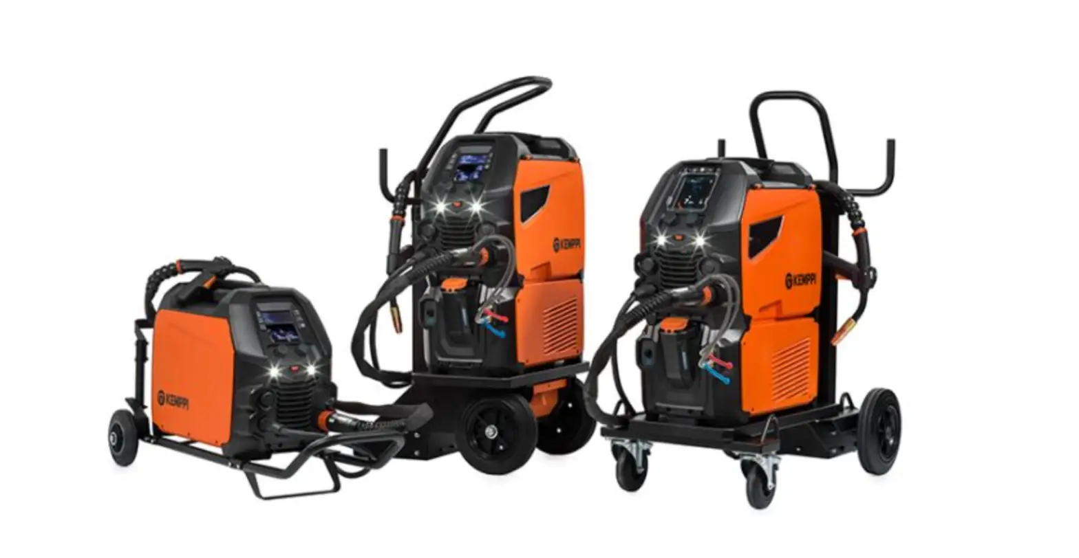
Master M 358 Operating manual – EN1.1 Equipment descriptionMaster M 358 device models (350 A) · Master M 358 G>> Generator-compatible >> Pulse device with automatic 1-MIG and pulse processes. Advanced MAX processes as optional. · Master M 358 GM >> Generator-compatible and multi-voltage >> Pulse device with automatic 1-MIG and pulse processes. Advanced MAX processes as optional. Both Master M 358 device models have a 4-roll wire feed mechanism with the maximum wire spool diameter of 300 mm. For the Master M 358 device part descriptions, refer to “Master M 358 device” on page 7.Master M 358 control panels · 2-knob 5.7″ TFT/LCD control panelMaster M cooling units · Master M Cooler · Master M Cooler MV (multi-voltage). For the cooling unit part descriptions, refer to “Master M Cooler cooling unit (optional)” on page 11.MIG welding guns · Flexlite GX welding guns with euro connector. For more information on the Flexlite GX welding guns, refer to Kemppi Userdoc.SubfeedersSubfeeder support can be added with a separate installation kit (contact your Kemppi dealer / service workshop for more information). · SuperSnake GTX subfeeder For more information on the SuperSnake GTX subfeeder, refer to Kemppi Userdoc.Welding programs · Welding program work pack (factory-installed) · 1-MIG Wise features: WiseSteel and WiseFusion · 1-MIG Wise features: WisePenetration+ (on-demand / at the time of purchase) · Additional 1-MIG and pulse welding programs (on-demand / at the time of purchase) · Additional MAX processes (on-demand / at the time of purchase) The welding programs included in the Master M work packs are shown here: “Welding program work packs” on page 90. For more information on acquiring welding programs and additional welding processes, contact your local Kemppi dealer.Optional accessories · 4-wheel carts · 2-wheel carts · Remote control HR40 (2-knob control) · Remote control HR43 (1-knob control) · Wire feeder cabinet heater · Power source air filter
© Kemppi
5
1921980 / 2242
Master M 358 Operating manual – ENFor more information on optional accessories, contact your local Kemppi dealer.EQUIPMENT IDENTIFICATIONSerial number Serial number of the device is marked on the rating plate or in another distinctive location on the device. It is important to make correct reference to the serial number of the product when ordering spare parts or making repairs for example. Quick Response (QR) code The serial number and other device-related identification information may also be saved in the form of a QR code (or a barcode) on the device. Such code can be read by a smartphone camera or with a dedicated code reader device providing fast access to the device-specific information.
© Kemppi
6
1921980 / 2242
1.2 Master M 358 deviceFront
Master M 358 Operating manual – EN
1. Transportation handle (also for mechanical lifting when the device is not installed on a cooling unit or cart) 2. Control panel (and hinged control panel cover) 3. Work lights with light switch in the middle>> Light switch: First press turns the lights on (full brightness), second press dims the lights (medium brightness), third press turns the lights off>> Includes a built-in battery (the battery is charged when the equipment is connected to mains) 4. Control cable connector 5. Earth return cable connector 6. Front locking interface>> For locking on top of the cooling unit or on the cart 7. Welding cable euro connector 8. Connector for subfeeder synchronization kit (optional) 9. Wire feed cabinet hatch.
© Kemppi
7
1921980 / 2242
Rear
Master M 358 Operating manual – EN
1. Shielding gas hose connector. 2. Mains cable 3. Power switch 4. Rear locking interface>> For locking on top of the cooling unit or on a cart.Inside wire feed cabinet
1. Rotameter for gas 2. Polarity terminals 3. Wire inch button>> Drive the filler wire forward (with arc off) 4. Gas test button>> Test the shielding gas flow and flush the gas line 5. Wire feed mechanism (refer to “Wire feed mechanism” on the next page) 6. Wire spool.
© Kemppi
8
1921980 / 2242
1.2.1 Wire feed mechanism
Master M 358 Operating manual – EN
1. Drive rolls and drive roll mounting caps 2. Middle guide tube locking clip 3. Middle guide tube 4. Inlet guide tube 5. Pressure handles 6. Pressure rolls and pressure roll mounting pins 7. Pressure roll locking arms 8. Outlet guide tube.For replacing the feed rolls, refer to “Installing and replacing feed rolls” on page 21. For replacing the wire guide tubes, refer to “Installing and replacing wire guide tubes” on page 23.1.2.2 Control panelThis section describes the controls and features of the Master M 358 control panel (TFT/LCD).
1. Left control knob (with push button function) 2. Right control knob (with push button function) 3. Memory channel selection (shortcut button) 4. View selection (shortcut button) 5. Welding parameters view (shortcut button).
© Kemppi
9
1921980 / 2242
For using the control panel, refer to “Using control panel” on page 36.
Master M 358 Operating manual – EN
© Kemppi
10
1921980 / 2242
1.3 Master M Cooler cooling unit (optional)Front
Master M 358 Operating manual – EN
1. Cooler container cap 2. Cooling liquid level indicator 3. Cooling liquid circulation button>> Keeping the button pressed activates the pump and circulates the cooling liquid throughout the system. Once released, the pump stops.4. Front locking interface >> For locking on the cart5. Front locking interface >> For locking to the power source6. Coolant inlet connector (red) 7. Coolant outlet connector (blue).Rear
1. Rear locking interface >> For locking to the power source2. Rear locking interface >> For locking on the cart.
© Kemppi
11
1921980 / 2242
Master M 358 Operating manual – EN2. INSTALLATIONDo not connect the equipment to the mains before the installation is complete.Do not modify the welding equipment in any way, except for the changes and adjustments covered in the manufacturer’s instructions. Place the machine on a horizontal, stable and clean ground. Protect the machine from rain and direct sunshine. Check that there is enough space for cooling air circulation in the machine vicinity.Before installation · Make sure to acknowledge and follow the local and national requirements regarding installation and use of highvoltage units. · Check the contents of the packages and make sure the parts are not damaged. · Before you install the power source on site, see the requirements for the mains cable type and fuse rating.Distribution networkThis Class A equipment is not intended for use in residential locations where the electrical power is provided by the public low-voltage supply system. There can be potential difficulties in ensuring electromagnetic compatibility in those locations, due to conducted as well as radiated radio-frequency disturbances. Master M power source 350A: Provided that the short circuit power of public low voltage system at the point of common coupling is higher than 2.4 MVA, this equipment is compliant with IEC 61000-3-11:2017 and IEC 61000-312:2011 and can be connected to public low voltage systems. It is the responsibility of the installer or user of the equipment to ensure, by consultation with the distribution network operator if necessary, that the system impedance complies with the impedance restrictions.
© Kemppi
12
1921980 / 2242
2.1 Installing power source mains plug
Only an authorized electrician is allowed to install the mains cable and plug.
Do not connect the machine to the mains before the installation is complete.
Install the 3-phase plug according to the Master M device and site requirements.The mains cable includes the following wires:1. Brown: L1 2. Black: L2 3. Grey: L3 4. Yellow-green: Protective earth
Cable type and fuse rating requirements:
Unit amperage 350 A (380-460 V) 350 A (380-460 / 220-230 V)
Cable type 4 mm2 4 mm2
Fuse rating 16 A 16 / 32 A
Master M 358 Operating manual – EN
© Kemppi
13
1921980 / 2242
2.2 Installing cooling unit (optional)The Master M cooling unit must be installed by authorized service personnel. Tools needed:1. Remove the small connector cover in the rear of the power source.
Master M 358 Operating manual – EN
2. Route the cooling unit’s connection cables so that they remain accessible through the next steps. 3. Lift the Master M device on top of the cooling unit so that the fixing plates align and go into their slots.Ensure that the cooling unit’s connection cables are not caught and/or damaged between the edges.
© Kemppi
14
1921980 / 2242
Master M 358 Operating manual – EN 4. Fix the units together with two screws (M5x12) in the front and two screws (M5x12) in the rear. 5. Connect the cooling unit cables.6. Replace the small connector cover.
© Kemppi
15
1921980 / 2242
Master M 358 Operating manual – EN2.3 Installing equipment on cart (optional)Master M has four transport unit options: a 4-wheel cart with a gas bottle rack (P45MT), a 4-wheel cart without a gas bottle rack (P43MT), a 2-wheel cart with a gas bottle rack (T25MT) and a 2-wheel cart without a gas bottle rack (T35A).The equipment installation principle and the bottom securing interface is the same with all carts. Tools needed:1. Install the cooling unit on the cart.
2. Fix the cooling unit to the cart with two screws (M5x12) in the front and two screws (M5x12) in the rear. 3. Install the Master M device on top of the cooling unit. Refer to “Installing cooling unit (optional)” on page 14 forinstallation details.4. T25MT 2-wheel cart: Secure the equipment to the cart with the two side connection brackets.With the T25MT cart, an additional securing bracket is attached to the device handle. Secure the bracket to the cart with the screws provided (M8x16) .
© Kemppi
16
1921980 / 2242
Master M 358 Operating manual – EN
T35A 2-wheel cart: The cart must be in horizontal position during welding.
For lifting the Master M equipment, refer to “Lifting equipment” on page 69.
© Kemppi
17
1921980 / 2242
Master M 358 Operating manual – EN2.4 Connecting welding gunMaster M is designed to be used with the Kemppi Flexlite GX welding guns. For the Flexlite GX operating instructions, refer to userdoc.kemppi.com.Always check that the wire liner, contact tip and gas nozzle are suitable for the job. 1. Push the welding gun connector into the euro connector and hand-tighten the collar. 2. If your setup includes a water-cooled gun, connect the cooling liquid hoses to the cooling unit. The hoses are color-coded.3. Install and load the filler wire as described in “Installing and changing wire” on page 24. 4. Check the gas flow. Refer to “Installing gas bottle and testing gas flow” on page 29 for more information.
© Kemppi
18
1921980 / 2242
2.5 Installing earth return cable1. Connect the earth return cable to the Master M machine’s earth return cable connector.
Master M 358 Operating manual – EN
© Kemppi
19
1921980 / 2242
Master M 358 Operating manual – EN2.6 Installing remote control (optional)Remote controls are optional. To enable remote operation, connect the remote control device to the Master M welding equipment. The remote control mode can be set and adjusted in the control panel settings (“Control panel: Device settings” on page 51).When the Remote mode is selected in the settings and both wireless and wired remotes are connected, the wired remote will be used. Remote control HR43/HR40 1. Connect the remote control cable to the control cable connector.2. To adjust the remote control parameters, refer to “Control panel: Device settings” on page 51.
© Kemppi
20
1921980 / 2242
Master M 358 Operating manual – EN2.7 Installing and replacing feed rollsReplace the feed rolls when the filler wire diameter or material changes. Select the feed rolls according to the tables in “Wire feeder consumables” on page 88. 1. Open the wire feed cabinet hatch. 2. Release the pressure handles on the wire feed mechanism.3. Open the locking arms to release the feed rolls.
4. Pull the pressure roll mounting pins and drive roll mounting caps off.
© Kemppi
21
1921980 / 2242
Master M 358 Operating manual – ENThe pressure rolls’ mounting pins have central axles attached to them, whereas the drive rolls’ central axles act as drive shafts attached directly to the wire feed mechanism/motor. 5. Remove the drive rolls and pressure rolls.6. Follow the previous steps in reverse to install the wire feed rolls. Align the cut on the drive rolls’ bottom with the pin on the drive shaft.7. Reattach the mounting caps and mounting pins to lock the drive and pressure rolls into their places. 8. Close the locking arms and lower the pressure handles on the feed rolls. Refer to “Installing and changing wire” onpage 24 for more information on the wire installation. 9. Close the wire feed cabinet hatch.
© Kemppi
22
1921980 / 2242
Master M 358 Operating manual – EN2.8 Installing and replacing wire guide tubesThe wire feed mechanism includes three wire guide tubes. Replace them when the filler wire diameter or material changes. Select the wire guide tubes according to the tables in “Wire feeder consumables” on page 88.When replacing the outlet guide tube, the welding gun must be detached.a. Inlet guide tube b. Middle guide tube c. Outlet guide tube To replace the wire guide tubes: 1. Release the pressure arms and remove the filler wire from the system. 2. Pull out the inlet guide tube (a) and insert a new one in its place. 3. Turn the locking clip aside to free the middle guide tube (b) for replacement. 4. Insert a new middle guide tube in its slot and push it properly in place. Ensure that the mark arrow points to thewire running direction.
5. Turn the locking clip back to lock down the new middle tube. 6. Replace the outlet guide tube (c) by pushing the old outlet tube out from either direction.
© Kemppi
23
1921980 / 2242
Master M 358 Operating manual – EN2.9 Installing and changing wireAlways ensure that the feed rolls are suitable for the filler wire (diameter and material) in question. For more information, refer to “Wire feeder consumables” on page 88.Install the welding gun to the Master M device before installing the wire spool. When changing the wire spool, remove the remaining filler wire from the welding gun and wire feed mechanism before removing the wire spool. To remove the wire spool: 1. Open the wire feed cabinet hatch. 2. Loosen and remove the spool fastener and remove the wire spool.To install the wire spool: 1. Insert the wire spool onto the hub. Secure the wire spool in place by inserting and tightening the spool fastener.Ensure that the wire spool is facing the right direction, the filler wire running from the bottom of the spool to the feed rolls.
© Kemppi
24
1921980 / 2242
Master M 358 Operating manual – EN
2. If needed, adjust the spool brake by turning the spool brake tightening knob in the center of the spool hub. To install the filler wire: 1. Release the filler wire end from the spool and cut off any deformed section so that the end is straight.Ensure that the filler wire does not spill from the spool when it is released. 2. File the tip of the filler wire smooth.Sharp edges on the filler wire tip may damage the wire liner. 3. Release the pressure arms to move the feed rolls apart.
© Kemppi
25
1921980 / 2242
Master M 358 Operating manual – EN 4. Guide the filler wire through the inlet guide tube (a) and middle guide tube (b) and into the outlet guide tube (c), which feeds the filler wire to the welding gun.5. Push the filler wire by hand into the gun so that the wire reaches the wire liner.6. Close the pressure arms so that the filler wire is locked between the feed rolls.
© Kemppi
26
1921980 / 2242
Master M 358 Operating manual – EN7. Adjust the pressure of the feed rolls with the pressure adjustment wheels. The pressure is the same for both feed roll pairs.
The graduated scales on the pressure handle indicate the pressure applied to the feed rolls. Adjust the pressure of the feed rolls according to the table below.
Filler wire material Fe/Ss solidMC/FC Al
Feed roll profile* V-grooveV-groove, knurled U-groove
Filler wire diameter (mm) 0.8-1.0 1.2 1.2 1.0 1.2
Adjustment (x100N) 1.5-2.0 2.0-2.5 1.0-2.0 0.5-1.0 1.0-1.5
Excessive pressure flattens the filler wire and may damage coated or cored filler wires. Excessive pressure also unnecessarily wears the feed rolls and increases gearbox load.8. Press the wire inch button (*) to drive the filler wire into the welding gun. Stop when the wire reaches the welding gun’s contact tip. The wire feed speed can be adjusted in the control panel.
Watch out for the wire when it reaches the contact tip and exits the gun.
© Kemppi
27
1921980 / 2242
Master M 358 Operating manual – EN9. Before welding, ensure that the welding parameters and settings conform to your welding setup. * Feed roll profiles and corresponding symbolsFeed roll profile Symbol V-grooveV-groove, knurledU-groove
© Kemppi
28
1921980 / 2242
Master M 358 Operating manual – EN2.10 Installing gas bottle and testing gas flowHandle gas bottles with care. There is a risk of injury if the gas bottle or the bottle valve is damaged!Always secure the gas bottle properly in an upright position to a special holder on the wall or on the welding equipment cart. Always keep the gas bottle valve closed when not welding. – If a transport unit with a gas bottle rack is used, install the gas bottle on the transport unit first, then make the connections. – Install the welding gun to the welding machine before installing and testing the gas bottle. – Do not use the whole contents of the bottle. – Always use an approved and tested regulator and flow meter. Contact your local Kemppi dealer for choosing the gas and the equipment. 1. Without gas bottle cart: Place the gas bottle in a suitable, secure location. 2. With gas bottle cart: Move the gas bottle on the transport unit’s gas bottle rack and secure it in place with the straps and fixing points provided.
© Kemppi
29
1921980 / 2242
Master M 358 Operating manual – EN3. If not already, connect the welding gun to the device (refer to “Connecting welding gun” on page 18). 4. Connect the gas hose to the welding device. 5. Open the gas bottle valve. 6. Press the gas test button (*) to test and adjust the gas flow. Use either the built-in rotameter or an external flowmeter and regulator for measuring and adjustment.
The gas test time is 20 seconds by default. The time can be changed in the control panel.
Recommended gas flow rates (for general guidance only):
TIG*
MIG**
Argon
5…15 l/min 10…25 l/min
Helium
15…30 l/min –
Argon + 18-25% CO2 –
10…25 l/min
CO2
–
10…25 l/min
* Depending on the gas nozzle size. ** Depending on the gas nozzle size and welding current.
© Kemppi
30
1921980 / 2242
Master M 358 Operating manual – EN2.11 How to get welding programsThe Master M 358 device comes with a welding program work pack preinstalled. These work pack versions cover the basic welding tasks with the automatic 1-MIG and pulsed welding process. The additional welding programs, Wise features (WiseSteel, WiseFusion, WisePenetration+) and MAX processes (MAX Cool, MAX Position, MAX Speed) are installed at the time of purchase according to your specific welding requirements. This can be done by your local Kemppi dealer. Welding programs can also be added later on. For more information on the available welding program options and installing the welding programs or software updates, contact your local Kemppi dealer or go to Kemppi.com. The manual MIG process doesn’t require additional welding programs. For applying the welding programs installed on your Master M 358 equipment, refer to “Control panel: Applying welding programs” on page 53. The list of installed welding programs on your equipment can be seen in the control panel’s Info view under Welding software. The welding programs included in the Master M 358 work packs are shown here: “Welding program work packs” on page 90.
© Kemppi
31
1921980 / 2242
Master M 358 Operating manual – EN3. OPERATIONBefore using the equipment, ensure that all the necessary installation actions have been completed according to your equipment setup and instructions.Welding is forbidden in places where there is an immediate fire or explosion hazard!The wire feed cabinet hatch must be kept closed when welding.Check that there is enough space for cooling air circulation in the machine vicinity.If the welding equipment is left unused for a longer period, disconnect the mains plug from the mains. Always check before use that shielding gas hose, earth return cable and clamp and mains cable are in serviceable condition. Ensure that the connectors are correctly fastened. Loose connectors can impair welding performance and damage connectors.
© Kemppi
32
1921980 / 2242
3.1 Preparing welding system for useBefore starting the use of the welding equipment:· Ensure the installation has been completed · Switch the welding equipment on · Prepare the cooler · Connect the earth return cable · Calibrate the welding cable (in MIG operation mode only)>> Refer to “Calibrating welding cable” on page 35 for instructions.Turning on welding systemTo turn on the welding equipment, turn the power source main switch to ON (I).
Master M 358 Operating manual – EN
Turn the main switch to start and shut down the welding equipment. Do not use the mains plug as a switch.If the welder is left unused for a longer period, detach the mains plug to disconnect it from the mains.Preparing cooler Fill the coolant container inside the cooler with Kemppi cooling liquid. For instructions on filling the cooler, refer to “Filling cooler and circulating coolant” below. To weld, you must pump the coolant through the system by pressing the coolant circulation button in the front panel of the cooling unit. Connecting earth return cableKeep the work piece connected to earth to reduce the risk of injury to users or damage to electrical equipment.Attach the earth return cable clamp on the work piece. Ensure that the contact surface is clean of metal oxide and paint and that the clamp is firmly secured. Selecting operation mode and process To select the operation mode (MIG/TIG/MMA), refer to “Control panel: Device settings” on page 51.For TIG welding, the polarity (+/-) must be switched. For information, refer to “Changing welding polarity” on page 67.3.1.1 Filling cooler and circulating coolantFill the cooler with 20-40 % coolant solution, for example, Kemppi cooling liquid.
© Kemppi
33
1921980 / 2242
1. Open the cooler cap. 2. Fill the cooler with coolant. Do not fill over the max. marking.
Master M 358 Operating manual – EN
3. Close the cooler cap.To circulate the coolant: Press the coolant circulation button in the cooler front panel (*). It activates the motor, which pumps the coolant to the hoses and to the welding gun. Complete the coolant circulation operation after each time you change the welding gun.
© Kemppi
34
1921980 / 2242
Master M 358 Operating manual – EN3.2 Calibrating welding cableThe welding cable resistance can be measured using the built-in cable calibration function without an additional measurement cable. This calibration function is available only in MIG operation mode. 1. Connect the earth return cable between the welding device and work piece. 2. Remove the welding gun gas nozzle. 3. Connect the welding gun to the welding device. 4. Turn the welding device on. 5. On the control panel, go to settings and enable cable calibration. 6. Touch the cleaned work piece briefly with the welding gun contact tip.There is no need to press the trigger. Trigger function is disabled at this stage. 7. Using the control panel, confirm the measured values.
© Kemppi
35
1921980 / 2242
Master M 358 Operating manual – EN3.3 Using control panelThe Master M 358 control panel includes advanced features and functions for MIG welding with the option to use Master M 358 also for TIG (DC) and MMA welding. The automatic 1-MIG process is available along with the Kemppi welding programs as well as Wise features and MAX processes (optional). For more information, refer to “How to get welding programs” on page 31.
General1. Left control knob >> Adjustment and selection2. Right control knob >> Adjustment and selection3. Memory channels button >> Shortcut to the memory channel selection >> Changed welding parameters can be quickly saved onto the active memory channel by keeping the Memory channels button pressed for approx. 2 seconds. This works in any view.4. View menu button >> Enter view selection >> Long press of the button returns to Home view, or if already in Home view, to the last used view.5. Welding parameters button >> Shortcut to the welding parameters view6. View selection >> Change view by turning the control knob (2) >> Confirm view change by pressing the control knob (2).
© Kemppi
36
1921980 / 2242
Views (7) A. Home view B. Weld Assist view C. Memory channels view D. WPS view E. Welding parameters view F. Weld history view G. Device settings view H. WLAN view I. Info viewAfter each weld, a weld summary (Weld data) is displayed briefly.3.3.1 Control panel: Home viewMaster M 358 control panel’s Home view is also the main welding view.
Master M 358 Operating manual – EN
1. Memory channel information 2. Applied welding parameters and functions 3. Wire feed speed (MIG) or welding current (TIG, MMA) 4. Active welding process 5. Applied device settings (e.g. remote control or subfeeder) 6. Welding voltage>> With 1-MIG process voltage fine tuning is displayed >> With MAX process a corresponding MAX parameter adjustment is displayed. 7. Configurable function for the right control knob button >> To define a shortcut, keep the right control knob button pressed for 3 seconds and select the shortcut functionfrom the list of available options. >> Once defined, the shortcut is used by short press of the right control knob button when in Home view. 8. Active user 9. Active operation mode.Control knob functions in Home viewLeft control knob:· Manual MIG: Wire feed speed adjustment · 1-MIG: Wire feed speed adjustment
© Kemppi
37
1921980 / 2242
Master M 358 Operating manual – EN· Pulse MIG: Wire feed speed adjustment · DPulse MIG: Wire feed speed adjustment and switching between pulse levels with control knob button · TIG/MMA: Welding current adjustment Right control knob: · Manual MIG: Welding voltage adjustment · 1-MIG: Fine tuning of welding voltage or Wise/MAX parameter adjustment · Pulse MIG: Fine tuning of welding voltage or Wise/MAX parameter adjustment · DPulse MIG: Fine tuning of welding voltage · MMA: Dynamics adjustment.With Wise features or MAX processes turned on, the control knob functions in Home view and during welding may differ from the above. For more information on these features and processes, refer to “Additional guidance to functions and features” on page 56.3.3.2 Control panel: Weld AssistWeld Assist is a wizard-like utility for easy selection of welding parameters. The utility walks the user step-by-step through the selection of required parameters. In Weld Assist, the selections are made with the two control knobs.To use Weld Assist with MIG welding:The currently selected welding program, including filler wire and shielding gas information, is shown and used as a basis in Weld Assist. If necessary, the welding program can be changed before continuing by selecting ‘Change welding program’. If the currently selected welding program (on the active memory channel) is not supported by Weld Assist, the user is guided to change the welding program. 1. To start, go to the Weld Assist view and select ‘Next’ with the control knob button.
2. Select:>> The welding joint type: butt joint / corner joint / edge joint / lap joint / T-joint / tube joint / tube+plate joint. >> The welding position: PA / PB / PC / PD / PE / PF / PG >> The plate thickness (1…10 mm). Note: With PG position, the maximum plate thickness is 3 mm.
© Kemppi
38
1921980 / 2242
Master M 358 Operating manual – EN
3. Weld Assist gives you a recommendation for these welding parameters:>> Welding process >> Wire feed speed >> Gas flow rate >> Travel speed >> Separate values for root and fill passes (where applicable).4. Confirm the Weld Assist’s recommendation for welding settings by selecting ‘Save’.
5. Select the memory channel slot for saving. 6. Once saved, the memory channel can be taken into use by selecting Use in Weld Assist, or later in the Memorychannels view. The welding parameters created with Weld Assist are still adjustable as per normal.Tip: You can go back step by step in Weld Assist by pressing the left control knob button.3.3.3 Control panel: ChannelsThe memory channel view can be accessed either via the panel’s view selection or by pressing the physical memory channel shortcut button above the display (refer to “Using control panel” on page 36 for more information).
© Kemppi
39
1921980 / 2242
Master M 358 Operating manual – ENThe amount of available memory channels differs between different operation modes: MIG (100 channels), TIG (10 channels) and MMA (10 channels).The operation mode set in the control panel Settings determines for which main welding process the memory channels are shown.
Changing memory channelTurn the right control knob to highlight the desired memory channel. The highlighted memory channel is automatically activated.Managing memory channelsThe memory channels are managed through the Actions menu.1. Enter the actions menu by pressing the right control knob. 2. Turn the control knob to highlight the desired action. 3. Select the action by pressing the right control knob. 4. Make further selections as required.Available actions are:· Save changes: Save changes to the currently selected channel · Save to…: Save the current settings to another channel · Delete: Delete the currently selected channel · Link to WPS: Link the currently selected channel to a weld pass on a digital welding procedure specification(dWPS) document. · Create channel: Create a new channel based on the welding program(s)>> MIG only: Welding programs can be filtered by base material, wire material, wire diameter, shielding gas and process. For more information, refer to “Control panel: Applying welding programs” on page 53.· Create from programs: Create new channels based on all of the unused welding programs available (in MIG mode only)· Delete all: Delete all channels.The skewed channel number in the top left corner of the channel selection indicates that the set welding parameters are different from the ones currently saved on the active memory channel:
© Kemppi
40
1921980 / 2242
Master M 358 Operating manual – ENTip: Changed welding parameters can be quickly saved onto the active memory channel by keeping the Memory channels button pressed for approx. 2 seconds. This works in any view.3.3.4 Control panel: WPS viewThe use of digital WPS (Welding Procedure Specification, dWPS) and WeldEye cloud service require a valid Kemppi WeldEye subscription with the Welding Procedures module. The Master M 358 equipment includes a link to a free trial registration featuring also a free trial option for WeldEye ArcVision. For more information on WeldEye, refer to weldeye.com or contact your Kemppi representative. To take the digital WPS feature in use, the equipment must be connected to the internet via the built-in wireless connection (WLAN). Refer to “Wireless connection (WLAN)” on page 61 for instructions. Trial registration Master M 358 comes preinstalled with a trial license for the WeldEye Welding Procedures module. The trial license can be activated by following these steps: 1. On the Master M 358 control panel, go to the WPS view. 2. Use a QR code reader on your mobile device to open the WeldEye web link or navigate to ‘https://re-gister.weldeye.io/weldeye’ on your web browser.
3. Complete the registration process as instructed on the registration page. You will be required to fill in the serial number and four-digit security pin of your Master M 358 machine. These can be found on the machine rating plate.The free trial registration includes both the WeldEye Welding Procedures and WeldEye ArcVision modules.Using dWPS The WPS view shows the digital WPSs with one or more weld passes assigned to the welder or welding station in the Kemppi WeldEye cloud service. To take a dWPS in use:
© Kemppi
41
1921980 / 2242
Master M 358 Operating manual – EN 1. Select the desired dWPS for viewing and for selecting a weld pass by turning the right control knob and pressing the right control knob button.If a dWPS and weld pass have already before been linked to the active memory channel, the WPS view opens directly to that WPS. To open the list of available dWPSs, select ‘Change WPS’. 2. Select a weld pass on the dWPS by turning the right control knob and enter the actions menu by pressing the right control knob button.>> The linked memory channel set as default is emphasized for each weld pass.
© Kemppi
42
1921980 / 2242
Master M 358 Operating manual – EN3. If a memory channel has been already linked to the weld pass, you can activate the selected weld pass and the default memory channel by selecting ‘Activate’.4. If a memory channel has not been linked to the weld pass previously, you can link the weld pass to an existing memory channel (‘Select linked channel’). A memory channel can also be linked to a weld pass on a dWPS through the Memory channels view by selecting ‘Link to WPS’ in the memory channel’s actions menu.Once a weld pass on a dWPS is activated, the default memory channel linked to it is automatically selected. This is indicated also in the home view and on screen during welding. The welding parameters are still manually adjustable, but the adjustment ranges defined on the active WPS are indicated on the screen. If you adjust the welding parameters outside the WPS adjustment range, the control panel shows a warning on the screen:
The active WPS can be deactivated by selecting ‘Stop using’ in the WPS’s weld pass actions menu.More feature descriptions here:>> “Digital Welding Procedure Specification (dWPS)” on page 62 >> “WeldEye ArcVision” on page 62
© Kemppi
43
1921980 / 2242
Master M 358 Operating manual – EN3.3.5 Control panel: Welding parametersThe Welding parameters view includes a start and stop curve for adjusting the most essential parameters for a weld. The bottom section of the view lists the available adjustments for the selected welding process. The welding process selection is based on the active memory channel and its settings.Many of the welding parameters are welding process specific and are visible and available for adjustment accordingly.
Adjusting welding parameters1. Turn the right control knob to highlight the desired welding parameter. 2. Press the right control knob to select the welding parameter for adjustment. 3. Turn the right control knob to adjust welding parameter value.>> Depending on the parameter to be adjusted, refer also to the Welding parameters table below for more details. 4. Confirm the new value / selection and close the adjustment view by pressing the right control knob.Saving welding parameters for later useA work channel is automatically created for the changed welding parameters. To save the set welding parameters on a memory channel, do one of the following:· Quick active channel option: Keep the Channels shortcut button pressed for approximately 2 seconds. >> This will save the parameter settings onto the currently active channel replacing its previous parameter settings.· Channels view option: Go to the Channels view and save the parameter settings onto a new channel. >> Refer to “Control panel: Channels” on page 39 for more information.
© Kemppi
44
1921980 / 2242
Master M 358 Operating manual – EN
Welding parameters and feature descriptions
MIG and 1-MIG welding parameters
The parameters listed here are available for adjustment with the MIG and 1-MIG processes.
Parameter
Parameter value
Description
Process
MIG, 1-MIG, Pulse, DPulse, MAX Cool, MAX Speed, MAX Position
This MIG welding process selection depends on the active welding program. For more information on the additional processes, refer to “Additional guidance to functions and features” on page 56.
Trigger logic
2T, 4T
Welding guns can have several alternative trigger operation modes (trigger logics). Most common are 2T and 4T. In 2T mode you hold the trigger down while welding. In 4T mode you press and release the trigger to start or to stop welding. For more information, refer to “Trigger logic functions” on page 56.
Pre gas
0.0 … 9.9 s, Auto, step 0.1 0.0 = OFF
Welding function that starts the shielding gas flow before the arc ignites. This ensures that the metal does not come into contact with air at the start of the weld. Time value is preset by the user. Used for all metals, but especially for stainless steel, aluminum and titanium.
Creep start
10…90 %, Auto, step 1
The Creep start function defines the wire feed speed before the welding arc ignites, that is, before the filler wire comes in contact with the workpiece. When the arc ignites, the wire feed speed is automatically switched to the normal user-set speed. The Creep start function is always on.
Touch Sense Ignition
AUTO/ON/OFF
Touch Sense Ignition (TSI) delivers minimum spatter and stabilizes the arc immediately after ignition.
Wire feed speed
0.50 … 25 m/min, step 0.05 or 0.1 Default = 5.00 m/min
Wire feed speed adjustment. When the wire feed speed is less than 5 m/min, the adjustment step is 0.05 and when the wire feed speed is 5 m/min or more, the adjustment step is 0.1.
Wire feed speed min
Min/Max = 0.5 … 25 m/min, step 0.1 Default = 0.5 m/min
Minimum and maximum limits for the wire feed speed adjustment.
Wire feed speed max
Min/Max = 0.5 … 25 m/min, step 0.1 Default = 25 m/min
Voltage
Min/Max = According to welding equipment specifications, step 0.1
Welding voltage adjustment and the minimum and maximum limits for the welding voltage adjustment. These parameters are available for adjustment in MIG only. In 1-MIG the voltage is defined by welding program.
© Kemppi
45
1921980 / 2242
Master M 358 Operating manual – EN
DynamicsCrater fill – Crater fill time – Crater fill wire feed speed – Crater fill voltage Post currentWire feed end step (WF end step) Post gas
-10.0 … +10.0, step 0.2 Default = 0ON/OFF0.1 … 10.0 s, Auto, step 0.1 Default = 1.0 s0.70 … 25.0 m/min, Auto, step 0.05 or 0.1 Default = 5 m/min8 … 45 V, Auto, step 0.1 V Default = 18V-30 … +30OFF/ON Default = OFF 0.0 … 9.9 s, Auto, step 0.1 0.0 = OFF
Controls the short circuit behavior of the arc. The lower the value the softer the arc, the higher the value the rougher the arc.(Not available with MAX Cool and MAX Speed.)When welding with high power, a crater is usually formed at the end of the weld. The Crater fill function decreases the welding power / wire feed speed at the end of the welding job so that the crater can be filled using a lower power level. With MIG process, Crater fill duration, wire feed speed and voltage are preset by the user.When the wire feed speed is less than 5 m/min, the adjustment step is 0.05 and when the wire feed speed is 5 m/min or more, the adjustment step is 0.1.For 1-MIG process, refer to the 1-MIG parameter table.Post current setting affects the wire length at the weld end, for example to prevent the wire from stopping too close to the weld pool. This also enables the optimum wire length for the start of the next weld.Wire feed end step feature prevents the filler wire from sticking to the contact tip when the welding ends.Welding function that continues the shielding gas flow after the arc has extinguished. This ensures that the hot weld does not come into contact with air after the arc is extinguished, protecting the weld and also the electrode. Used for all metals. Especially stainless steel and titanium require longer post gas times.
© Kemppi
46
1921980 / 2242
Master M 358 Operating manual – EN
1-MIG welding parameters
The parameters listed here are available for adjustment only with the 1-MIG process.
Parameter
Parameter value
Description
Trigger logic
2T, 4T, Powerlog (2 levels or 3 levels)
Welding guns can have several alternative trigger operation modes (trigger logics). Most common are 2T and 4T. In 2T mode you hold the trigger down while welding. In 4T mode you press and release the trigger to start or to stop welding. Note that enabling Powerlog opens additional Powerlog settings in the Welding parameters view. For more information, refer to “Trigger logic functions” on page 56.
Upslope – Upslope start level– Upslope time
ON/OFF10 … 100 %, Auto, step 1 Default = 500.1 … 5 s, Auto, step 0.1 Default = 0.10
Upslope is a welding function that determines the time, during which the welding current gradually increases to the desired welding current level at the start of the weld. The upslope start level and time are preset by the user.
Hot start – Hot start level – Hot start time
ON/OFF-50 … +200 %, Auto, step 1 Default = 400.0 … 9.9 s, Auto, step 0.1 Default = 1.2 s
Welding function that uses higher or lower wire feed speed and welding current at the start of the weld. After the Hot start period the current changes to normal welding current level. This facilitates the start of the weld especially with aluminum materials. The Hot start level and time (only in 2T trigger mode) are preset by the user.
Wise feature
None, WiseFusion, WisePenetration+, WiseSteel
When selected, a list of available Wise features is opened for selection. For more information on these features, refer to “Additional guidance to functions and features” on page 56. (Not available with MAX Cool, MAX Speed and MAX Position.)
Fine tuning
Example: -10.0 … +10.0 V * Step 0.1 V
Fine tuning of the welding voltage. * The voltage range for fine tuning is defined by the active welding program.
Crater fill – Crater fill start level – Crater fill time – Crater fill end level
ON/OFF10 … 150 %, Auto, step 1 Default = 1000.0 … 10.0 s, Auto, step 0.1 Default = 1.0 s10 … 150 %, Auto, step 1 Default = 30
When welding with high power, a crater is usually formed at the end of the weld. The Crater fill function decreases the welding power / wire feed speed at the end of the welding job so that the crater can be filled using a lower power level. With 1-MIG process, Crater fill start level, duration and end level are preset by the user.
Current
15 … 350 A, step 1 Default = 50 A
Welding current adjustment with WisePenetration+ only.
© Kemppi
47
1921980 / 2242
Master M 358 Operating manual – EN
Pulse/DPulse welding parameters
The parameters listed here are available for adjustment in addition to the MIG and 1-MIG welding parameters.
Parameter
Parameter value
Description
Pulse current %
-10 … +15 %, step 1
The pulse current fine tuning relative to the current with Pulse and DPulse welding processes.
DPulse ratio
10 … 90 %, step 1
This adjusts the double pulse time percentage, i.e. how long the double pulse is at the first pulse level. The second pulse level is determined in relation to the first level setting.
DPulse frequency
0.4 … 8.0 Hz, Auto, step 0.1
This adjusts the double pulse frequency. How long it takes from the start of 1st level to the end of 2nd level.
DPulse level 1: Wire feed speed
0.50 … 25 m/min, step 0.05 or 0.1
First double pulse level wire feed speed (and minimum / maximum values for wire feed speed). When the wire feed speed is less than 5 m/min, the adjustment step is 0.05 and when the wire feed speed is 5 m/min or more, the adjustment step is 0.1.
DPulse level 1: Fine tuning
-10 … +10, step 1
Fine tuning of the welding voltage.
DPulse level 1: Dynamics
-10.0 … +10.0, step 0.2 Default = 0
Controls the short circuit behavior of the arc. The lower the value the softer the arc, the higher the value the rougher the arc.
DPulse level 2: Wire feed speed
0.50 … 25 m/min, step 0.05 or 0.1
Second double pulse level wire feed speed. The DPulse level 2 wire feed speed changes automatically when the DPulse level 1 wire feed speed setting is adjusted. When the wire feed speed is less than 5 m/min, the adjustment step is 0.05 and when the wire feed speed is 5 m/min or more, the adjustment step is 0.1.
DPulse level 2: Fine tuning
-10 … +10, step 1
Fine tuning of the welding voltage.
DPulse level 2: Dynamics
-10.0 … +10.0, step 0.2 Default = 0
Controls the short circuit behavior of the arc. The lower the value the softer the arc, the higher the value the rougher the arc.
MAX Speed parameters
The parameters listed here are MAX Speed process specific.
Parameter
Parameter value
MAX Speed frequency
100 … 800 Hz, Auto step 10
Description MAX Speed frequency setting.
© Kemppi
48
1921980 / 2242
Master M 358 Operating manual – EN
MAX Position parameters
The parameters listed here are MAX Position process specific.
Parameter
Parameter value
MAX Position frequency
-0.5 … +0.5 Hz, step 0.1 Default = 0
Pulse current %
-10 … 15 %, step 1 Default = 0
Plate thickness
3.0 … 12.0 mm
TIG welding parameters
The parameters listed here are available for adjustment with the TIG process.
Parameter
Parameter value
Trigger logic
2T, 4T
Post gas
0.0 … 9.9 s, step 0.1 0.0 = OFF
Current
15 … 350 A, step 1 Default = 50 A
MMA welding parameters
The parameters listed here are available for adjustment with the MMA process.
Parameter
Parameter value
Dynamics
-10.0 … +10.0, step 0.2 Default = 0
Hot start level
-30 … +30 Default = 0
Current
15 …350 A, step 1 Default = 50 A
Description MAX Position frequency fine tuning.MAX Position pulse current adjustment.MAX Position plate thickness setting.Description Welding guns can have several alternative trigger operation modes (trigger logics). Most common are 2T and 4T. In 2T mode you hold the trigger down while welding. In 4T mode you press and release the trigger to start or to stop welding. Welding function that continues the shielding gas flow after the arc has extinguished. This ensures that the hot weld does not come into contact with air after the arc is extinguished, protecting the weld and also the electrode. Used for all metals. Especially stainless steel and titanium require longer post gas times. Welding current adjustment.Description Controls the short circuit behavior of the arc. The lower the value the softer the arc, the higher the value the rougher the arc. Welding function that uses higher or lower wire feed speed and welding current at the start of the weld. After the Hot start period the current changes to normal welding current level. This facilitates the start of the weld especially with aluminum materials. In MMA the Hot start level is preset by the user. Welding current adjustment.
© Kemppi
49
1921980 / 2242
Master M 358 Operating manual – EN3.3.6 Control panel: Weld historyThe Weld history view collects the information of the past welds (the last 10) into one view for later checking. To change how the weld data averages are calculated (with or without slope phases) refer to “Control panel: Device settings” on the next page.Heat input calculation in weld history view The heat input of a weld can be calculated by entering the weld length into the weld’s history entry. 1. Select ‘Set length’ by pressing the right control knob button. 2. Set the weld length by turning the right control knob. 3. Confirm the weld length for calculation by pressing the control knob button.3.3.7 Control panel: Info viewThe Info view shows information on the device usage. Through this view it is also possible to access the error logs, list of installed welding programs, additional operating information and device info, such as the software version and equipment serial numbers.
© Kemppi
50
1921980 / 2242
Master M 358 Operating manual – EN
3.3.8 Control panel: Device settings
Changing settings1. Turn the right control knob to highlight the desired settings parameter. 2. Press the right control knob to select the settings parameter for adjustment. 3. Turn the right control knob to select the settings value.>> Depending on the settings parameter to be adjusted, refer also to the Settings table below for more details. 4. Confirm the new value / selection and close the adjustment view by pressing the right control knob.
Settings
Parameter Mode
Parameter value MIG/TIG/MMA
DescriptionNote: For TIG welding the polarity (+/-) must also be switched. For more information, refer to “Changing welding polarity” on page 67.
© Kemppi
51
1921980 / 2242
Master M 358 Operating manual – EN
Remote controlRemote mode (with 1-knob remote control)
OFF/Remote/Gun Default = OFFWire feed speed / Channel
Remote mode (with 2-knob remote control)
Welding parameter / Channel
Subfeeder (with MIG only)Safe wire inch (with MIG only) Wire retract – Wire retract delay – Wire retract length Gas guardLanguageWeld data time
Subfeeder model / None Default = NoneOFF/ONOFF/ON2…10 s, step 1 Default = 5 s 1…10 cm, step 1 Default = 2 cm OFF/ON Default = OFFAvailable languages0…30 s, step 1 0 = OFF Default = 5 s
If remote controller is not connected, this selection is not available.This determines what is changed with the remote, wire feed speed or memory channel (available channels: 1…5). If remote controller is not connected and remote not selected, this selection is not available.This determines what is changed with the remote, welding parameter(s) or memory channel (available channels: 1…5). The adjusted parameters are process-specific. If remote controller is not connected and remote not selected, this selection is not available. Note: When the remote mode is set to ‘Channel’, only the left remote control knob is in use.If a compatible subfeeder is connected, select the subfeeder from the list. Compatible subfeeders: SuperSnake GTX (10 m, 15 m, 20 m, 25 m), Binzel PP401D, Binzel PP36D.When ON, and the arc doesn’t ignite, the filler wire is fed 5 cm When OFF, 5 m of filler wire is fed.This is an automatic wire retract feature. Once the arc is extinguished, the wire is retracted for additional safety. The user can change the wire retract delay and length settings. Note: Wire retract function is disabled if a subfeeder is connected.Gas guard prevents welding without shielding gas.This allows the user to select the control panel language from a list of available languages.This defines if and how long the weld data summary is shown after each weld.
© Kemppi
52
1921980 / 2242
Master M 358 Operating manual – EN
Weld data averageBrightness Date Time (24h) Screensaver
Without slopes / Entire weld Default = Without slopes1…10 Current date Current time OFF/1…120 min, step 1 Default = 5 min
This feature allows the user to change how the weld data averages are calculated: with or without the slope phases in the beginning and in the end of the weld. This setting affects the calculation of the averages for the following: welding voltage (terminal and arc voltage), welding current, welding power and wire feed speed.The control panel display brightness.Date setting.Time setting in 24h format.The screensaver image is shown on display after the set time period. By default, the Kemppi logo is shown. To change the screensaver image, refer to “USB update” on page 64.
Cable calibration (with MIG only)Water coolingVRD (with MMA only)
Start/CancelOFF/Auto/ON Default = AutoAlways ON (with MMA only)
The date and time and the calibration information of the previous calibration is also shown. Refer to “Calibrating welding cable” on page 35 for cable calibration.When ON is selected, the coolant is circulated continuously, and when Auto is selected, the coolant is circulated only during welding.Voltage reduction device (VRD) reduces the open-circuit voltage to maintain below a certain voltage value.
Backup Restore Factory reset
(Selection)(Selection)Reset/Cancel Default = Cancel
This allows the settings to be saved on a connected USB memory stick.This allows the settings to be restored from a connected USB memory stick.This resets the machine to factory settings.
3.3.9 Control panel: Applying welding programsTo select and apply a MIG welding process and program, a corresponding memory channel must be created.When creating the memory channel for a particular MIG welding process, the selection of welding programs can be narrowed down based on the available MIG welding processes: Manual, 1-MIG, MAX Speed (optional), MAX Position (optional) and MAX Cool (optional).Use the welding program that is in accordance with your welding setup (e.g. welding wire and gas properties).
© Kemppi
53
1921980 / 2242
Master M 358 Operating manual – EN1. Go to the Memory channels view. (Refer to “Control panel: Channels” on page 39 for more information.) 2. Enter the actions menu. 3. Select Create channel.>> A filter view opens.
4. Use the filter options (e.g. material, wire material or wire diameter) to find the welding programs best suited for the purpose.The operation mode set in the panel Settings determines for which main welding process the programs here are shown. In MIG mode, the process selection in the Create channel view allows to narrow down the search more specifically to different MIG processes.If manual MIG is selected as the process, other filter and welding program selections are disabled.5. Once ready, go to the Welding program selection at the bottom to view the suitable welding programs.
6. Select a welding program. >> The selected welding program is now shown in the filter view.
© Kemppi
54
1921980 / 2242
7. To save, scroll down to Save to and select it.
Master M 358 Operating manual – EN
Select the memory channel slot for saving and confirm. Once ready, you can continue to the Welding parameters view to adjust the welding settings for the new channel, create a new channel or go back to the Channels view.Tip: It is also possible to create new channels based on all of the unused welding programs available for the selected operation mode by selecting Create all in the Channel view’s actions menu. This option uses the available memory channel slots.3.3.10 Control panel: Weld data viewAfter each weld, a weld summary is displayed briefly. To change the weld data view duration or how the weld data averages are calculated (with or without slope phases), refer to “Control panel: Device settings” on page 51.
© Kemppi
55
1921980 / 2242
3.4 Additional guidance to functions and featuresThis section summarizes the Master M 358 functions and features and how to use them.
Master M 358 Operating manual – EN
3.4.1 Trigger logic functionsYou can select the trigger logic in the Welding parameters view. 2T In 2T, pressing the trigger ignites the arc. Releasing the trigger switches the arc off.
4TIn 4T, pressing the trigger starts the pre gas, and releasing the trigger ignites the arc. Pressing the trigger again switches the arc off. Releasing the trigger ends the post gas.
PowerlogPowerlog trigger logic function allows the user to switch between two or three different power levels. In Powerlog, pressing the trigger starts the pre gas, and releasing the trigger ignites the arc. A quick press of the trigger during welding switches between levels (after the last defined power level the first level is selected). Long-pressing the trigger at any of the levels during welding switches the arc off.
To take Powerlog into use, go to the control panel’s Welding parameters view and select Powerlog as the trigger logic. Once selected, choose whether 2 or 3 power levels are used. Still in the Welding parameters view, set up the power levels for this function. The parameters available for adjustment for each level are:· Wire feed speed and its minimum and maximum values · Voltage / Fine tuning · Dynamics (not available with MAX Cool).The wire feed speed of each level can also be adjusted in the Home view. Pressing the left control knob button changes between levels. Green color indicates the selected Powerlog level:
© Kemppi
56
1921980 / 2242
Master M 358 Operating manual – EN
Powerlog trigger logic is not available with manual MIG, MAX Speed, MAX Position or DPulse processes.Powerlog trigger logic cannot be used together with a remote control. If a Powerlog memory channel is selected when a remote control is in use, the trigger logic is automatically switched to 4T.3.4.2 1-MIG1-MIG is a MIG/MAG welding process where the voltage is defined automatically when you adjust the wire feed speed. The voltage is calculated based on the welding program in use. The process is suitable for all materials, shielding gases and welding positions. 1-MIG supports WiseSteel, WisePenetration+ and WiseFusion features, as well as various optimized welding programs.>> To take 1-MIG into use, go to the Memory channels view and select an existing memory channel with 1-MIG process.If there aren’t any 1-MIG memory channels available, create a new one for 1-MIG process by selecting an available 1-MIG welding program for the channel. Follow the instructions in “Control panel: Applying welding programs” on page 53.3.4.3 WiseFusion featureThe WiseFusion welding feature enables adaptive arc length control, which keeps the arc optimally short and focused. WiseFusion increases the welding speed and penetration and decreases heat input. WiseFusion can be used throughout the power range (short arc, globular arc and spray arc). WiseFusion is compatible with 1-MIG, MAX Position and pulsed MIG welding processes.>> To take WiseFusion into use, go to the control panel’s Welding parameters view and apply the WiseFusion feature.>> To adjust the welding power/wire feed speed, in the control panel’s Home view, turn the left control knob. >> To fine tune the heat output while welding, in the control panel’s Home view, turn the right control knob. For more information on Wise products, visit www.kemppi.com.3.4.4 WisePenetration+ featureIn standard MIG/MAG welding, changes in stick-out length cause welding current to fluctuate. WisePenetration+ maintains constant welding current by controlling the wire feed speed according to the stick-out length. This ensures stable and effective penetration and prevents burn through. WisePenetration+ also adjusts the voltage adaptively, which keeps
© Kemppi
57
1921980 / 2242
Master M 358 Operating manual – ENthe arc focused and optimally short. WisePenetration+ enables welding with Reduced Gap Technology (RGT) and is compatible with 1-MIG welding process.>> To take WisePenetration+ into use, go to the control panel’s Welding parameters view and apply the WisePenetration+ feature.>> To adjust the welding current while welding, in the control panel’s Home view, turn the left control knob. >> To fine tune the heat output while welding, in the control panel’s Home view, turn the right control knob. For more information on Wise products, visit www.kemppi.com.3.4.5 WiseSteel featureThe WiseSteel welding feature is based on modifying the conventional MIG/MAG arcs to enable higher quality of welds. WiseSteel improves the arc control, reduces spatter and helps create an optimally-formed weld pool.>> To take WiseSteel into use, go to the control panel’s Welding parameters view and apply the WiseSteel feature. >> To adjust the welding power/wire feed speed while welding, in the control panel’s Home view, turn the left con-trol knob. >> To fine-tune the heat output while welding, in the control panel’s Home view, turn the right control knob. When using WiseSteel, different adjustment methods are applied at different power ranges (different arcs). The wire feed speed / current indicator shows the arc range: Short arc — Globular arc — Spray arc. Short arc range: · WiseSteel is based on adaptive short arc control; that is, the process adjusts the short circuit ratio. This creates an easily-adjustable arc and less spatter. Within the short arc range, the shape of the current is similar to the traditional short arc welding. When a short arc is used in vertical up welding where weaving motion is applied, WiseSteel ensures good quality through adapting to the changes in the stick-out length. Globular arc range: · Globular arc means that WiseSteel fluctuates the power between short arc and spray arc at a low frequency, so that the average power stays within the globular arc range. This results in less spatter than conventional globular arc welding, and a welding pool that enables excellent structural durability. Spray arc range: · Within the spray arc range, WiseSteel is based on adaptive arc length control, which keeps the arc optimally short. WiseSteel also utilizes micro-pulsed welding current. This creates a well-formed weld pool that enables excellent bead geometry and optimal penetration with smooth and durable joints, and speeds up the work. The pulsing is not noticeable to the welder. The shape and control of the current are close to the conventional spray arc welding. For more information on Wise products, visit www.kemppi.com.
© Kemppi
58
1921980 / 2242
Master M 358 Operating manual – EN
3.5 Pulse weldingThe advantages of Pulse are a higher welding speed and deposition rate compared to short-arc welding, lower heat input compared to spray-arc welding, a spatter-free globular arc and smooth appearance of the weld. Pulse is suitable for all position welding. It is excellent for welding aluminum and stainless steel, especially when the material thickness is small.Pulse
Pulse is a synergic MIG/MAG welding process where the current is pulsed between the base current and the pulse current.>> To take Pulse welding process into use, go to “Control panel: Channels” on page 39 and select an available Pulse channel.If there aren’t any Pulse memory channels available, create a new one for Pulse process by selecting an available Pulse welding program for the channel. Follow the instructions in “Control panel: Applying welding programs” on page 53.>> Once selected, the corresponding Pulse welding process parameters become available for adjustment in the Welding parameters view. For more information, refer to the pulse welding parameters in “Control panel: Welding parameters” on page 44.DPulse
DPulse is a double-pulse MIG/MAG welding process with two separate power levels. The welding power varies between these two levels. The parameters of each level are controlled independently.>> To take DPulse welding process into use, go to “Control panel: Channels” on page 39 and select an available Pulse channel.If there aren’t any Pulse memory channels available, create a new one for Pulse process by selecting an available Pulse welding program for the channel. Follow the instructions in “Control panel: Applying welding programs” on page 53.>> Once selected, the corresponding DPulse welding process parameters become available for adjustment in the Welding parameters view. For more information, refer to the pulse welding parameters in “Control panel: Welding parameters” on page 44.3.5.1 MAX Cool processMAX Cool is a synergic MIG/MAG welding process that is designed for root pass welds and sheet metal applications. MAX Cool is suitable for all welding positions and provides a smooth arc, reducing spatter.>> To take MAX Cool into use, go to the control panel’s Welding parameters view and apply MAX Cool. Optionally, go to the Memory channels view and create a new memory channel with MAX Cool process.>> To adjust the wire feed speed while welding, or in the control panel’s Home view, turn the left control knob. The adjustment’s effect on the plate thickness is also shown.>> To fine tune the heat output while welding, or in the control panel’s Home view, turn the right control knob. Max Cool supports these filler wire and shielding gas combinations: · Fe solid & Ar + 8…25 % CO2 (1.0 mm, 1.2 mm) · Fe solid & CO2 (1.0 mm, 1.2 mm) · Ss solid & Ar + 2 % CO2 (1.0 mm, 1.2 mm)
© Kemppi
59
1921980 / 2242
Master M 358 Operating manual – EN
· CuSi3 & Ar (1.0 mm) · CuAl8 & Ar (1.0 mm).3.5.2 MAX Position processMAX Position is a synergic MIG/MAG welding process optimized for vertical fillet welds (position: PF). MAX Position automatically switches between two separate power levels. The two power levels can use the same welding process or two different welding processes.>> To take MAX Position into use, go to the control panel’s Welding parameters view and apply MAX Position. Optionally, go to the Memory channels view and create a new memory channel with MAX Position process.>> In Welding parameters view, MAX Position frequency can be adjusted and the optional WiseFusion feature can be applied. The ratio of the two power levels is preset.>> To adjust the average wire feed speed while welding, or in the control panel’s Home view, turn the left control knob. The adjustment’s effect on the plate thickness is also shown.>> To fine tune the welding voltage while welding, or in the control panel’s Home view, turn the right control knob.MAX Position supports these filler wire and shielding gas combinations:· Fe solid & Ar + 18% CO2 (1.0 mm, 1.2 mm) · Fe solid & Ar + 8% CO2 (1.0 mm, 1.2 mm) · Fe MC + 18% CO2 (1.2 mm) · Ss solid & Ar + 2% CO2 (1.0 mm, 1.2 mm) · AlMgl & Ar (1.0 mm, 1.2 mm)MAX Position supports these plate thicknesses:· 3…12 mmMAX Position utilizes also other welding processes (depending on the material):· Fe & Fe MC: 1-MIG (with low power) and Pulse MIG (with high power) · Ss & Al: Pulse MIG (throughout the power range).3.5.3 MAX Speed processMAX Speed is a synergic pulsed MIG/MAG welding process. It is designed to maximize the welding speed and to minimize the heat input by modifying the conventional MIG/MAG arcs. MAX Speed is designed for steel and stainless steel welding applications mainly in the PA and PB positions. It is suitable for plate thicknesses above 2.5 mm, the ideal maximum plate thickness being approximately 6 mm.MAX Speed operates within the spray arc range. Welding current is pulsed with constant frequency and amplitude. Arc length is controlled with the normal voltage control. MAX Speed’s low-amplitude pulsing enables an effective transfer mode with lower wire feed speed than with conventional MIG/MAG arc. The pulsing is not noticeable to the welder.>> To take MAX Speed into use, go to the control panel’s Welding parameters view and apply MAX Speed. Optionally, go to the Memory channels view and create a new memory channel with MAX Speed process.>> In Welding parameters view, the MAX Speed frequency can be adjusted. >> To adjust the wire feed speed while welding, or in the control panel’s Home view, turn the left control knob.The adjustment’s effect on the plate thickness is also shown. >> To fine tune the welding voltage while welding, or in the control panel’s Home view, turn the right controlknob.MAX Speed supports these filler wire and shielding gas combinations:· Fe solid & Ar + 18% CO2 (1.0 mm, 1.2 mm) · Fe solid & Ar + 8% CO2 (1.0 mm, 1.2 mm) · Fe MC & Ar + 18% CO2 (1.2 mm) · Ss solid & Ar + 2% CO2 (1.0 mm, 1.2 mm).
© Kemppi
60
1921980 / 2242
3.6 Wireless connection (WLAN)To connect the welding equipment to your local wireless network: 1. On the control panel, go to the WLAN view. 2. Turn the WLAN feature on by turning and pressing the right control knob.
Master M 358 Operating manual – EN
3. Enter your local wireless network’s SSID (Service Set Identifier), i.e. the name of your Wi-Fi network.
>> Use the right control knob to select letters. 4. Enter your WLAN password.
>> Use the right control knob to select letters. Once connected, the WLAN status information is shown.
© Kemppi
61
1921980 / 2242
Master M 358 Operating manual – EN
The WLAN mode is set to ‘Client’ by default and it cannot be changed.3.6.1 Digital Welding Procedure Specification (dWPS)The use of digital WPS (Welding Procedure Specification, dWPS) and WeldEye cloud service require a valid Kemppi WeldEye subscription with the Welding Procedures module. For more information on WeldEye, refer to weldeye.com or contact your Kemppi representative. Digital Welding Procedure Specification (dWPS) is a WPS in digital format that can be set to observe the welding parameters of the Master M 358 equipment. The WPSes can be read on the control panel display and/or a memory channel can be linked with a WPS. The Master M 358 control panel provides a couple of ways to achieve this:>> In the main WPS view: Follow the more detailed steps in “Control panel: WPS view” on page 41. >> In the Memory channels view via activating an existing memory channel: Open the memory channel ‘Actions’and choose to link it with a WPS. In the view that opens, select the WPS and weld pass information to be linked with the memory channel. More detailed information on memory channels is in “Control panel: Channels” on page 39.3.6.2 WeldEye ArcVisionThe use of WeldEye cloud service requires a valid Kemppi WeldEye subscription. The Master M 358 equipment includes a link to a free trial registration featuring also a free trial option for WeldEye ArcVision. For more information on WeldEye, refer to weldeye.com or contact your Kemppi representative. The WeldEye’s ArcVision module is intended for cloud-based tracking of the welding operations carried out with the welding equipment. The ArcVision on the welding device itself is a connection feature for connecting to the WeldEye cloud service. The actual welding information gathered by the welding equipment is passed on to the WeldEye cloud where it can be accessed using a desktop computer and an internet browser. To take the WeldEye ArcVision feature in use, the equipment must be connected to the internet via the built-in wireless connection (WLAN). Refer to “Wireless connection (WLAN)” on the previous page for instructions. Master M 358 comes preinstalled with a trial license for ArcVision. The trial license can be activated by following these steps:
© Kemppi
62
1921980 / 2242
Master M 358 Operating manual – EN1. On the Master M 358 control panel, go to the WPS view. 2. Use a QR code reader on your mobile device to open the WeldEye web link or navigate to ‘https://re-gister.weldeye.io/weldeye’ on your web browser.3. Complete the registration process as instructed on the registration page. Once finished, the equipment is connected to WeldEye ArcVision. You will be required to fill in the serial number and four-digit security pin of your Master M 358 machine. These can be found on the machine’s rating plate. The free trial registration includes both the WeldEye Welding Procedures and WeldEye ArcVision modules.3.6.3 WeldEye with DCMWith Master M 358, the WeldEye connection option is built-in. The WeldEye welding management software is also available for use with an additional Digital Connectivity Module (DCM) device. DCM is connected directly to the Master M 358 machine’s control connection with the cables and adapters delivered with the DCM device.
For more information on installing and using the DCM device, refer to userdoc.kemppi.com (DCM/WeldEye).Discover WeldEye universal welding management software WeldEye is your primary tool and storage space for keeping your welding-related documents in order. WeldEye is a universal solution for managing welding production.
© Kemppi
63
1921980 / 2242
Master M 358 Operating manual – ENWeldEye’s modular structure is based on various useful functions that serve the needs of wide-ranging industries and welding-related tasks: · Welding procedures>> Includes the digital library and management of pWPS, WPQR and WPS templates according to the most important welding standards.· Personnel and qualifications >> Includes the management and renewal processes of all personnel – welders and inspectors – qualification certificates.· Quality management >> Includes quality verification functionalities with digital WPS and qualification compliance control against automatically collected digital welding data.· Welding management >> Includes document register functionalities and features for comprehensive welding project documentation and management.For more information on WeldEye, refer to www.weldeye.com.3.6.4 USB backup and restoreThe USB backup feature allows the current welding parameters, memory channels and other settings to be backed up on a USB memory stick. 1. Turn the welding machine on. 2. If creating a backup, go to the device settings and select Backup. 3. If restoring from a backup, go to the device settings and select Restore. 4. Open the USB connector cover and connect the USB memory stick to the Master M 358 control panel.
5. Follow the steps on the control panel screen to complete the backup/restore operation.3.6.5 USB updateThe USB update feature allows the firmware to be updated as well as welding programs, processes and features to be installed using a USB memory stick.
© Kemppi
64
1921980 / 2242
Master M 358 Operating manual – ENThere can be only one ZIP file on the USB memory stick inserted into the welding system at once. This can be either a dedicated firmware pack for this welding system or a welding program and license pack (matching the power source serial number). For more information on the available software and compatibility, contact your local Kemppi representative.Firmware and welding software 1. Ensure you have the correct firmware/software ZIP package saved on your computer for the welding equipment inquestion. 2. Connect the USB memory stick to the computer. 3. Prepare the USB memory stick by copying the firmware/software ZIP file into the root folder of the memory stick. 4. Turn the welding equipment on. 5. Open the USB connector cover and connect the USB memory stick to the Master M 358 control panel.
6. The update process starts automatically. Follow the on-screen instructions.Custom screensaver imageThe custom screensaver image must first be prepared at https://kemp.cc/screensaver and then copied onto the USB memory stick. The supported image file formats are JPG, PNG and GIF.1. On your computer web browser, go to https://kemp.cc/screensaver. 2. Following the on-screen instructions, upload, edit and download the new screen saver image onto a USB memorystick. 3. Connect the USB memory stick to the Master M 358 control panel following the same principle as with the softwareupdates (previous chapter) and the on-screen instructions.The screensaver image is shown during start-up and when the control panel has been idle for a predefined time. The screensaver settings can be adjusted in “Control panel: Device settings” on page 51.
© Kemppi
65
1921980 / 2242
3.7 Using remote controlRemote control HR43 To adjust the wire feed speed, turn the knob on the remote control.
Master M 358 Operating manual – EN
To change the memory channel instead of the wire feed speed with the remote, change the remote mode setting in the “Control panel: Device settings” on page 51. Remote control HR40 To adjust the welding parameters, turn the knobs on the remote control. In the automatic 1-MIG mode the HR40 control knob functions are defined by the selected 1-MIG process and reflect the adjustments of the control panel’s two control knobs.In the manual MIG mode the adjustments on the remote control as well as the minimum and maximum values for the adjusted parameters can be set in the control panel settings (“Control panel: Device settings” on page 51).With HR40 remote control, the minimum and maximum values affect also the resolution of the remote control adjustment.
© Kemppi
66
1921980 / 2242
Master M 358 Operating manual – EN3.8 Changing welding polarityWelding polarity needs to changed for TIG welding. Also, some filler wires require changing the welding polarity. Check the recommended welding polarity on the filler wire package.Before handling electrical parts, ensure the welding device is disconnected from the mains. Tools needed:17 mm 1. Turn off the welding device and disconnect it from the mains. 2. Open the wire feed cabinet hatch. 3. Remove the protective rubber covers from the polarity terminals.Use caution when handling electrical parts.4. Remove the terminal tightening bolts and washers.
© Kemppi
67
1921980 / 2242
5. Connect the cables to the polarity terminals according to the polarity recommendation. 6. Replace the washers and bolts. Tighten to 17 Nm torque. 7. Replace the protective rubber covers.
Master M 358 Operating manual – EN
© Kemppi
68
1921980 / 2242
Master M 358 Operating manual – EN3.9 Lifting equipmentIf a gas bottle is installed on cart, DO NOT attempt to lift the cart with the gas bottle in place. 4-wheel cart: 1. Ensure that the welding equipment is properly secured to the cart. 2. Connect the 4-legged chain or straps from the hoist hook to the four lifting points on the cart on both sides of thewelding equipment.2-wheel cart (T25MT only): 1. Ensure that the welding equipment is properly secured to the cart. 2. Connect the hoist hook to the lifting handle on the cart.
Do not lift the equipment when it is installed on the T35A cart.
© Kemppi
69
1921980 / 2242
Master M 358 Operating manual – EN4. MAINTENANCEWhen considering and planning routine maintenance, consider the operating frequency of the welding system and the working environment. Correct operating of the welding machine and regular maintenance helps you avoid unnecessary downtime and equipment failure.
© Kemppi
70
1921980 / 2242
Master M 358 Operating manual – EN4.1 Daily maintenanceDisconnect the power source from the mains before handling electrical cables.Welding machine maintenance Follow these maintenance procedures to maintain the proper functioning of the welding machine: · Check that all covers and components are intact. · Check all the cables and connectors. Do not use them if they are damaged and contact service for replacements. · Check the wire feed rolls and the pressure handle. Clean and lubricate with a small quantity of light machine oil ifneeded. For repairs, contact Kemppi at www.kemppi.com or your dealer. Welding gun maintenance For Flexlite GX MIG gun instructions, refer to userdoc.kemppi.com.
© Kemppi
71
1921980 / 2242
Master M 358 Operating manual – EN4.2 Periodic maintenanceOnly qualified service personnel is allowed to carry out periodic maintenance.Only an authorized electrician is allowed to carry out electrical work. Before removing the cover plate, disconnect the power source from the mains and wait for about 2 minutes before discharging the capacitor. Check the electric connectors of the unit at least every six months. Clean oxidized parts and tighten loose connectors. Where applicable, use the correct tension torque when fastening loose parts. Clean the outside parts of the unit from dust and dirt, for example, with a soft brush and vacuum cleaner. Also clean the ventilation grill at the back of the unit. Do not use compressed air, there is a risk that the dirt will compact even more tightly into gaps of cooling profiles. Do not use pressure washing devices.
© Kemppi
72
1921980 / 2242
Master M 358 Operating manual – EN4.3 Service workshopsKemppi Service Workshops complete the welding system maintenance according to the Kemppi service agreement. The main aspects in the service workshop maintenance procedure are: · Cleanup of the machine · Maintenance of the welding tools · Checkup of the connectors and switches · Checkup of all electric connections · Checkup of the power source mains cable and plug · Repair of defective parts and replacement of defective components · Maintenance test · Test and calibration of operation and performance values when needed Find your closest service workshop at Kemppi website.
© Kemppi
73
1921980 / 2242
Master M 358 Operating manual – EN
4.4 Troubleshooting
The problems listed and the possible causes are not definitive, but suggest some typical situations that may turn up during normal use of the welding system.
Welding device: Problem The welding device does not power upThe welding device stops working
Recommended actionsCheck that the mains cable is plugged in properly.Check that the mains switch of the power source is at the ON position.Check that the mains power distribution is on.Check the mains fuse and/or the circuit breaker.Check that the interconnection cable between the power source and the wire feeder is intact and properly attached.Check that the earth return cable is connected.Gas-cooled gun may have overheated. Wait for it to cool down.Check that none of the cables is loose.The wire feeder may have overheated. Wait for it to cool down and see that the welding current cable is properly attached.The power source may have overheated. Wait for it to cool down and see that the cooling fans work properly and the air flow is unobstructed.
Wire feeding: Problem The filler wire on the spool unravels The wire feed mechanism does not feed the filler wire
Recommended actionsCheck that the spool locking cover is closed.Check that the filler wire has not run out.Check that the filler wire is properly routed through the feed rolls to the wire liner.Check that the pressure handle is properly closed.Check that the feed roll pressure is adjusted correctly for the filler wire.Check that the welding cable is properly connected to the wire feeder.Blow compressed air through the wire liner to check that it is not blocked.
Weld quality: Problem
Recommended actions
© Kemppi
74
1921980 / 2242
Dirty and/or poor quality weld Varying welding performanceHigh spatter volume “Error codes” on the next page
Master M 358 Operating manual – ENCheck that the shielding gas has not run out. Check that the shielding gas flow is unobstructed. Check that the gas type is correct for the application. Check the polarity of the gun/electrode. Check that the welding procedure is correct for the application. Check that the wire feed mechanism is adjusted properly. Blow compressed air through the wire liner to check that it is not blocked. Check that the wire liner is correct for the selected wire size and type. Check the welding gun contact tip’s size, type and wear. Check that the welding gun is not overheating. Check that the earth return clamp is properly attached to a clean surface of the workpiece. Check the welding parameter values and welding procedure. Check the gas type and flow. Check the polarity of the gun/electrode. Check that the filler wire is correct for the current application.
© Kemppi
75
1921980 / 2242
Master M 358 Operating manual – EN
4.5 Error codes
In error situations, the control panel displays the number, title and possible cause of the error, and a proposed action to fix the issue.
Error Code 1 2 3 4 510 12 13 14 1617202426 273335
Title
Possible cause
Power source not calibrated
Power source calibration has been lost.
Too low mains voltage
Voltage in mains network is too low.
Too high mains Voltage in mains network is too high. voltage
Power source is Too long welding session with high power. overheated
Internal 24V voltage is too low
Power source contains an inoperative 24V power supply unit .
Unsupported There is an unsupported welding process welding process in the memory channel.
Welding cable failure
Plus and minus cables are connected together.
IGBT overcurrent Inoperative mains transformer in power source.
IGBT overheated Too long welding session with high power or high ambient temperature.
Main transformer is overheated
Too long welding session with high power or high ambient temperature.
Phase is missing from mains supply
One or more phases are missing from the mains supply.
Power source cooling failure
Cooling capacity is reduced in the power source.
Cooling liquid overheated
Too long welding session with high power or high ambient temperature.
Cooling liquid not circulatingCooler not foundWelding cable calibration failureToo high mains current
No cooling liquid or circulation is blocked.Cooling is turned on in the settings menu, but cooler is not connected to power source or cabling is faulty. Welding cable calibration failed.Current drawn from the mains is too high.
Proposed actionRestart the power source. If problem persists, contact Kemppi service.Restart the power source. If problem persists, contact Kemppi service.Restart the power source. If problem persists, contact Kemppi service.Do not shut down, let the fans cool the machine. If fans are not running, contact Kemppi serviceRestart the power source. If problem persists, contact Kemppi service.Check that all memory channel definitions are supported.Check the connections of welding cable and earth return cable.Restart the power source. If problem persists, contact Kemppi service.Do not shut down, let the fans cool the machine. If fans are not running, contact Kemppi service.Do not shut down, let the fans cool the machine. If fans are not running, contact Kemppi serviceCheck the mains cable and its connectors. Check the voltage of mains supply.Clean the filters and clear any dirt from the cooling channel. Check that the cooling fans are running. If not, contact Kemppi service.Do not turn off the cooler. Let the liquid circulate until the fans cool it down. If fans are not running, contact Kemppi service.Check the liquid level in the cooler. Check hoses and connectors for blockage.Check the cooler connections. Ensure that the cooling is turned off in the settings menu, if the cooler is not in use.Check the welding system cables and their connections.Reduce welding power.
© Kemppi
76
1921980 / 2242
Master M 358 Operating manual – EN
40
VRD error
Open circuit voltage exceeds the VRD limit. Restart the power source. If problem persists, contact Kemppi service.
42
High current in There may be too much pressure in the
Adjust the feed roll pressure. Clean the wire line.
wire feeder
wire feed rolls or dirt in the wire line.
Change worn parts in the welding gun.
motor
43
Overcurrent in There may be too much pressure in the
Adjust the feed roll pressure. Clean the wire line.
wire feeder
wire feed rolls or dirt in the wire line.
Change worn parts in the welding gun.
motor
44
Wire speed
Faulty sensor or wiring in wire feeder.
measurement is
missing
Restart the welding system. If problem persists, contact Kemppi service.
45
Low gas pres- Shielding gas pressure is too low.
sure
Check and adjust the shielding gas flow.
61
Operation is not Subfeeder is connected, but it has not been Go to the system settings menu on the control panel
allowed
selected in the system settings.
and select your subfeeder model and type.
65
Subfeeder not Use of subfeeder is not allowed with selec- Remove the subfeeder or change the welding pro-
allowed
ted welding process.
cess.
244
Internal memory Initialization failed (%sub:%device).
failure
Restart welding system. If problem persists, contact Kemppi service.
250
Internal memory Memory communication failed (%sub-
failure
:%device).
Restart welding system. If problem persists, contact Kemppi service.
© Kemppi
77
1921980 / 2242
Master M 358 Operating manual – EN4.6 Installing and cleaning power source air filter (optional)An optional power source air filter can be purchased separately. The air filter comes with a fixed casing designed to be mounted directly onto the power source air intake.Using the optional air filter decreases the rated power levels of the power source as follows (output 40 °C): 60% >>> 45% and 100% >>> 100%-20A. This is due to the slightly reduced cooling air intake. Tools needed:Installation and replacement 1. Place the air filter assembly onto the power source air intake, and lock it in place with the clips on the edge of thecasing.
© Kemppi
78
1921980 / 2242
Master M 358 Operating manual – ENCleansing 1. Remove the air filter from the power source by releasing the clips on the edge of the air filter casing. 2. Blow the air filter clean with compressed air.
© Kemppi
79
1921980 / 2242
4.7 Disposal
Master M 358 Operating manual – EN
Do not dispose of any electrical equipment with normal waste!In observance of WEEE Directive 2012/19/EU on waste of electrical and electronic equipment and European Directive 2011/65/EU on the restriction of the use of certain hazardous substances in electrical and electronic equipment, and their implementation in accordance with national law, electrical equipment that has reached the end of its life must be collected separately and taken to an appropriate environmentally responsible recycling facility. The owner of the equipment is obliged to deliver a decommissioned unit to a regional collection center, as per the instructions of local authorities or a Kemppi representative. By applying these European Directives you improve the environment and human health.
© Kemppi
80
1921980 / 2242
Master M 358 Operating manual – EN5. TECHNICAL DATATechnical data: · For Master M 358 device technical data, refer to “Master M 358 device” on the next page. · For Master M Cooler cooling unit technical data, refer to “Master M cooling unit” on page 86. Additional information: · For ordering information, refer to “Master M 358 ordering info” on page 87. · For wire feeder consumable information, refer to “Wire feeder consumables” on page 88. · For welding program work packs, refer to “Welding program work packs” on page 90.
© Kemppi
81
1921980 / 2242
5.1 Master M 358 device
Master M 358 G
Master M 358
Feature
Mains connection voltage
Mains connection cable
Input power at rated maximum current
Maximum supply current Effective supply current Idle state power consumption
I1max @ 380…460 V I1eff @ 380…460 V MIG, TIG @400
No-load state power consumption MMA (power save) @ 400 V
MMA (fans ON) @ 400 V
No-load voltage
Open circuit voltage
VRD voltage
MMA
Fuse
Slow
Output at +40 °C
40 %
60 %
100 % MIG
Welding current and voltage range MIG
TIG
MMA
Voltage adjustment range
MIG
Power factor at rated maximum cur- @ 400 V rent
Efficiency at rated maximum current
Operating temperature range
Storage temperature range
EMC class
Minimum short-circuit power of supply network
Gun connection
Wire feed mechanism
Diameter of feed rolls
Filler wires
Fe
Ss
MC/FC
3~50 Hz HO7RN-F I1eff P1idle U0 Uav
SSC
© Kemppi
82
Master M 358 Operating manual – EN358 G Value 380…460 V ±10 % 4 mm² 14 kVA21.3 … 17.1 A 13.5 … 10.8 A 18 W 18 W 119 W 55 … 69 V 53 … 64 V 24 V 16 A 350 A (MMA 330 A) 280 A 220 A 15 A / 10 V … 350 A / 45 V 15 A / 1 V … 350 A / 45 V 15 A / 10 V … 330 A / 45 V 10 … 40 V 0.9187 %-20…+40 °C -40…+60 °C A 2.4 MVAEuro 4-roll, single-motor 32 mm 0.8 … 1.2 mm 0.8 … 1.2 mm 0.8 … 1.2 mm1921980 / 2242
Wire feed speed Maximum wire spool weight Maximum wire spool diameter Maximum shielding gas pressure Control panel Degree of protection External dimensions Package external dimensions
AlLxWxH LxWxH
Weight Voltage supply for auxiliary devices Voltage supply for cooling unit Recommended minimum generator power Wired communication type
@ 400 V
Wireless communication type
– Wi-Fi standard – Bluetooth version – Operating frequencies
Lithium-ion battery
Standards Master M 358 GMMaster M 358 Feature Mains connection voltage
3~50 Hz
Mains connection cable
HO7RN-F
Input power at rated maximum current
Maximum supply current Effective supply current Idle state power consumption
I1max @ 220…230 V I1max @ 380…460 V I1eff @ 220…230 V I1eff @ 380…460 V MIG/TIG @400
Built-inSgenI1max I1max I1eff I1eff P1idle
Master M 358 Operating manual – EN0.8 … 1.2 mm 0.5 … 25 m/min 20 kg 300 mm 0.5 MPa 5.7″ LCD IP23S 602 x 298 x 447 mm 610 x 300 x 445 mm, with cooler 700 mm 27 kg 12 V 24 V 20 kVACANInternal wireless module WUBT-236ACN(BT) IEEE 802.11 ac/a/b/g/n4.2 (LE)2.412…2.484 GHz, 5.150…5.850 GHz SAMSUNG SDI: INR18650-26J; 3,6 V; 2600 mAh LG CHEM: ICR18650HE4; 3,6 V; 2500 mAh IEC 60974-1, -10358 GM Value 220…230 V ±10 % 380…460 V ±10 % 4 mm² 14 kVA21.1 … 17 A 21.3 … 17.1 A 13.3 … 10.8 A 13.5 … 10.8 A 20 W
© Kemppi
83
1921980 / 2242
No-load state power consumption MMA (power save) @ 400 V
MMA (fans ON) @ 400 V
No-load voltage
@ 220…230 V
U0
@ 380…460 V
U0
Open circuit voltage
Uav
VRD voltage
MMA
Fuse
Slow
Output at +40 °C
40 %
60 %
100 %
Welding current and voltage range MIG
TIG
MMA
Voltage adjustment range
MIG
Power factor at rated maximum cur- @ 400 V rent
Efficiency at rated maximum current
Minimum short-circuit power of supply network
Gun connection
Wire feed mechanism
Diameter of feed rolls
Filler wires
Fe
Ss
Mc/Fc
Al
Wire feed speed
Maximum wire spool weight
Maximum wire spool diameter
Maximum shielding gas pressure
Control panel
Operating temperature range
Storage temperature range
EMC class
380…460 V 220…230 V 380…460 V 220…230 V 380…460 V 220…230 V 380…460 V 220…230 V 380…460 V 220…230 V 380…460 V 220…230 V SSCBuilt-in
© Kemppi
84
Master M 358 Operating manual – EN20 W 120 W 54 … 56 V 55 … 69 V 53 … 64V 24 V 32 A (220…230 V) 16 A ( 380…460 V) 350 A (MMA 330 A) 300 A (MMA 280 A) 280 A 240 A 220 A 190 A 15 A / 10 V…350 A / 45 V 15 A / 10 V…300 A / 40 V 15 A / 1 V…350 A / 45 V 15 A / 1 V…300 A / 40 V 15 A / 10 V…330 A / 45 V 15 A / 10 V…280 A / 40 V 10 … 40 V 0.9187 %2.4 MVAEuro 4-roll, single-motor 32 mm 0.8 … 1.2 mm 0.8 … 1.2 mm 0.8 … 1.2 mm 0.8 … 1.2 mm 0.5 … 25 m/min 20 kg 300 mm 0.5 MPa 5.7″ LCD -20…+40 °C -40…+60 °C A1921980 / 2242
Degree of protection External dimensions Package external dimensions
LxWxH LxWxH
Weight Voltage supply for auxiliary devices Voltage supply for cooling unit
Recommended minimum generator power Wired communication typeWireless communication type
@ 400 V
– Wi-Fi standard – Bluetooth version – Operating frequencies
Lithium-ion battery
Standards
380…460 V 220…230 VSgen
Master M 358 Operating manual – ENIP23S 602 x 298 x 447 mm 610 x 300 x 445 mm, with cooler 700 mm 27 kg 12 V 24 V 24 V 20 kVACANInternal wireless module WUBT-236ACN(BT) IEEE 802.11 ac/a/b/g/n4.2 (LE)2.412…2.484 GHz, 5.150…5.850 GHz SAMSUNG SDI: INR18650-26J; 3,6 V; 2600 mAh LG CHEM: ICR18650HE4; 3,6 V; 2500 mAh IEC 60974-1, -10
© Kemppi
85
1921980 / 2242
5.2 Master M cooling unit
Master M Cooler
Master M Cooler
Feature
Supply voltage
Maximum supply current
@ 380…460 V
Cooling power
@ 1 l/min
Recommended coolant
Maximum coolant pressure
Tank volume
Operating temperature range
With recommended coolant
Storage temperature range
EMC class
Degree of protection
When mounted
Package external dimensions L x W x H
Weight
Without accessories
Standards
U1 I1max
Master M Cooler MV
Master M Cooler MV
Feature
Supply voltage
U1
Maximum supply current
@ 220…230 V
@ 380…460 V
Cooling power
@ 1 l/min
Recommended coolant
Maximum coolant pressure
Tank volume
Operating temperature range
With recommended coolant
Storage temperature range
EMC class
Degree of protection
When mounted
Package external dimensions L x W x H
Weight
Without accessories
Standards
I1max I1max
© Kemppi
86
Master M 358 Operating manual – ENValue 380…460 V +/- 10 % 0.7 A 1.0 kW MGP 4456 (Kemppi mixture) 0.4 MPa 3l -20…+40 °C-40…+60 °C A IP23S 635 x 305 x 292 mm 14.9 kg IEC 60974-2, -10Value 220…240 V +/- 10 % 380…460 V +/- 10 % 1.0 A 0.7 A 1.0 kW MGP 4456 (Kemppi mixture) 0.4 MPa 3l -20…+40 °C-40…+60 °C A IP23S 635 x 305 x 292 mm 14.9 kg IEC 60974-2, -101921980 / 2242
5.3 Master M 358 ordering infoFor Master M 358 ordering information and optional accessories, refer to Kemppi.com.
Master M 358 Operating manual – EN
© Kemppi
87
1921980 / 2242
Master M 358 Operating manual – EN
5.4 Wire feeder consumables
This section lists the feed rolls and wire guide tubes available both separately and in consumable kits. The consumable kits contain recommended feed roll and wire guide tube combinations for selected filler wire materials and diameters. The wire feeder consumables can be ordered in Configurator.kemppi.com.In the tables, standard refers to plastic feed rolls and heavy-duty refers to metal feed rolls. The materials mentioned first refer to primary suitability and the materials mentioned inside brackets refer to secondary suitability.
Wire feeder consumable kits The table below lists the recommended consumable kits for selected filler wire materials and diameters.
Wire feeder consumable kits
Filler wire material
Feed roll profile*
Fe (MC/FC)
V-groove
Ss (Fe, Cu)
V-groove
Ss (Fe)
V-groove
MC/FC Al
V-groove, knurled U-groove
Filler wire diameter (mm) 0.8-0.9 1.0 1.2 0.8-0.9 1.0 1.2 0.8-0.9 1.0 1.2 1.0 1.2 1.0 1.2
Consumable kit code, standard F000488 F000489 F000490 F000455 F000456 F000457 F000499 F000500 F000461 F000462
Consumable kit code, heavy-duty F000492 F000493 F000494 F000458 F000459 F000460 F000502 F000503 –
Wire guide tubes The table below lists the wire guide tubes available.
Wire guide tubes Filler wire material Al, Ss (Fe, MC/FC)Fe, MC/FC
Filler wire diameter (mm) 0.6 0.8-0.9 1.0 1.2 0.6 0.8-0.9 1.0 1.2
Inlet guide tubeSP007293 SP007294 SP007295 SP007296 (SP007293) SP007536 SP007537 SP007538
Middle guide tubeSP007273 SP007274 SP007275 SP007276 (SP007273) (SP007274) (SP007275) (SP007276)
Outlet guide tubeSP016608 SP011440 SP011441 SP011442 SP016613 SP016614 SP016615 SP016616
© Kemppi
88
1921980 / 2242
Master M 358 Operating manual – EN
Feed rolls The table below lists the standard feed rolls available.
Feed rolls, standard Filler wire material Fe, Ss, Cu (Al, MC/FC)
Feed roll profile* V-groove
MC/FC (Fe)
V-groove, knurled
Al (MC/FC, Ss, Fe, Cu) U-groove
Filler wire diameter (mm) 0.6 0.8-0.9 1.0 1.2 1.0 1.2 1.0 1.2
Drive roll codeW001045 W001047 W000675 W000960 W001057 W001059 W001067 W001069
The table below lists the heavy-duty feed rolls available.
Feed rolls, heavy-duty
Filler wire material
Feed roll profile*
Fe, Ss (MC/FC)
V-groove
MC/FC (Fe) (MC/FC, Ss, Fe)
V-groove, knurled U-groove
Filler wire diameter (mm) 0.8-0.9 1.0 1.2 1.0 1.2 1.0 1.2
Drive roll codeW006074 W006076 W004754 W006080 W006082 W006088 W006090
* Feed roll profiles and corresponding symbols: Feed roll profile Symbol V-groove
V-groove, knurled
U-groove
Pressure roll code W001046 W001048 W000676 W000961 W001058 W001060 W001068 W001070Pressure roll code W006075 W006077 W004753 W006081 W006083 W006089 W006091
© Kemppi
89
1921980 / 2242
Master M 358 Operating manual – EN
5.5 Welding program work packs
Welding program work packs include a set of standard welding programs to allow welding with e.g. automatic 1-MIG and pulse processes. For more information on the available Master M welding program options and installing the welding programs or software updates, contact your local Kemppi dealer or go to Kemppi.com.
1-MIG work pack:
Welding program A01 A02 A11 A12 C01 C03 C11 C13 F01 F02 F03 F04 F11 F12 F13 F14 F21 F22 F23 F24 M04 R04 S01 S02 S03 S04 S82 S84
Process 1-MIG 1-MIG 1-MIG 1-MIG 1-MIG 1-MIG 1-MIG 1-MIG 1-MIG 1-MIG 1-MIG 1-MIG 1-MIG 1-MIG 1-MIG 1-MIG 1-MIG 1-MIG 1-MIG 1-MIG 1-MIG 1-MIG 1-MIG 1-MIG 1-MIG 1-MIG 1-MIG 1-MIG
Wire material AlMg5 AlMg5 AlSi5 AlSi5 CuSi3 CuSi3 CuAl8 CuAl8 Fe Fe Fe Fe Fe Fe Fe Fe Fe Fe Fe Fe Fe Metal Fe Rutil Ss Ss Ss Ss FC-CrNiMo FC-CrNiMo
Wire diameter 1.0 1.2 1.0 1.2 0.8 1.0 0.8 1.0 0.8 0.9 1.0 1.2 0.8 0.9 1.0 1.2 0.8 0.9 1 1.2 1.2 1.2 0.8 0.9 1.0 1.2 0.9 1.2
Shielding gas Ar Ar Ar Ar Ar Ar Ar Ar Ar+18%CO2 Ar+18%CO2 Ar+18%CO2 Ar+18%CO2 Ar+8%CO2 Ar+8%CO2 Ar+8%CO2 Ar+8%CO2 CO2 CO2 CO2 CO2 Ar+18%CO2 Ar+18%CO2 Ar+2%CO2 Ar+2%CO2 Ar+2%CO2 Ar+2%CO2 Ar+18%CO2 Ar+18%CO2
Description Standard Standard Standard Standard Standard: Brazing Standard: Brazing Standard: Brazing Standard: Brazing Standard Standard Standard Standard Standard Standard Standard Standard Standard Standard Standard Standard Standard Standard Standard Standard Standard Standard Standard Standard
© Kemppi
90
1921980 / 2242
Master M 358 Operating manual – EN
Pulse work pack: The Pulse work pack includes also all 1-MIG work pack welding programs.
Welding program A01 A02 A11 A12 C01 C03 C11 C13 F01 F02 F03 F04 F11 F12 F13 F14 M04 S01 S02 S03 S04
Process Pulse Pulse Pulse Pulse Pulse Pulse Pulse Pulse Pulse Pulse Pulse Pulse Pulse Pulse Pulse Pulse Pulse Pulse Pulse Pulse Pulse
Wire material AlMg5 AlMg5 AlSi5 AlSi5 CuSi3 CuSi3 CuAl8 CuAl8 Fe Fe Fe Fe Fe Fe Fe Fe Fe Metal Ss Ss Ss Ss
Wire diameter 1.0 1.2 1.0 1.2 0.8 1.0 0.8 1.0 0.8 0.9 1.0 1.2 0.8 0.9 1.0 1.2 1.2 0.8 0.9 1.0 1.2
Shielding gas Ar Ar Ar Ar Ar Ar Ar Ar Ar+18%CO2 Ar+18%CO2 Ar+18%CO2 Ar+18%CO2 Ar+8%CO2 Ar+8%CO2 Ar+8%CO2 Ar+8%CO2 Ar+18%CO2 Ar+2%CO2 Ar+2%CO2 Ar+2%CO2 Ar+2%CO2
Description Standard Standard Standard Standard Standard: Brazing Standard: Brazing Standard: Brazing Standard: Brazing Standard Standard Standard Standard Standard Standard Standard Standard Standard Standard Standard Standard Standard
© Kemppi
91
 report this ad
1921980 / 2242
References
Kemppi – Welding Equipment and Software
Redirecting
Configurator
Kemppi – Welding Equipment and Software
Welding Management Software – Cloud Service – WeldEye
Trademarks
Welding Management Software – Cloud Service – WeldEye
Redirecting
Kemppi – Welding Equipment and Software
Kemppi screensaver
Kemppi – Welding Equipment and Software
Configurator
Kemppi symbols
Welding Management Software – Cloud Service – WeldEye
MIG welding guns
General
Welding Management Software – Cloud Service – WeldEye
SuperSnake
Contact info for Kemppi and Kemppi dealers – Kemppi
[xyz-ips snippet=”download-snippet”]