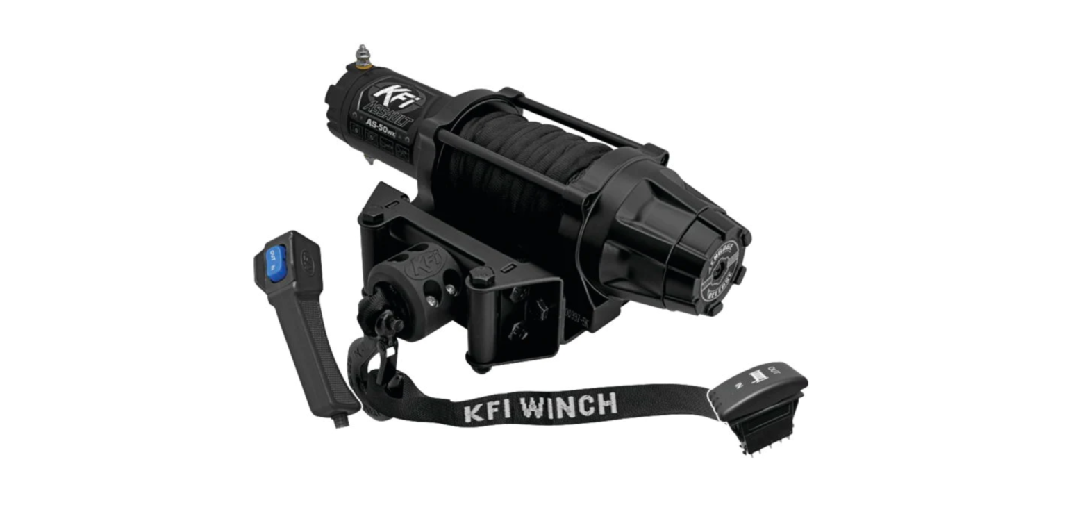
AS-50wx Assault Series Synthetic Cable UTV-SxS Winch
Place serial label here for reference.OPERATOR’S MANUAL
ASSAULT SERIES SYNTHETIC CABLE UTV/SxS WINCHMODEL #AS-50wx5,000 LB. (2268 KG)
READ AND SAVE THIS MANUAL. This manual contains important safety precautions which should be read and understood before operating the product. Failure to do so could result in serious injury. This manual should remain with the product. Specifications, descriptions, and illustrations in this manual are as accurate as known at the time of publication, but are subject to change without notice.
SERIAL NO. LABEL Suppor t:or visit www.kfiproducts.com
Made in China – REV 20220817
KFI Products – Kappers Fabricating, Inc., Spring Valley, MN USA
MODEL #AS-50wx 5,000LB (2268KG) WINCH
TABLE Of CONTENTS
Table of ConTenTs
Introduction………………………………. 1 Maintenance …………………………… 13
Accessories………………………………………..1 Motor ………………………………………………13
This Manual………………………………………..1Safety Definitions………………………. 1
Lubrication ……………………………………….13 Synthetic Cable Inspection …………………..13
Important Safety Instructions ……… 2 Cable Assembly Replacement ………………14
Controls and Features………………… 4 Specifications …………………………. 15
Installation ……………………………….. 5 Performance:…………………………………….15
Mount the Winch …………………………………5 Parts Diagram……………………………………16
Winch Assembly – Generic Install ……………5 Mount the Contactor …………………………….6 Install UTV Dash Mounted Rocker Switch …6
Parts List………………………………………….17Troubleshooting ………………………. 18 Warranty ………………………………… 19
Mount the Hand Remote Socket ……………..6 Contact Information ……………………………20
Wiring the Winch …………………………………7
Winch Wiring Diagram ………………………….8
Motor End Terminal Rotation ………………….8
Controller Wiring Diagram ……………………..9
Cable Hook Stopper Installation and Use ….9
General Tips for Safe Operation …………….10
Self Recovery ……………………………………10
Winching Techniques …………………………11
Synthetic Cable Usage ………………………..12
Snow Plow Usage………………………………12
Protective Sheath……………………………….12
MODEL #AS-50wx 5,000LB (2268KG) WINCH
INTRODUCTION
InTroduCTIon
safeTy defInITIons
Congratulations on your purchase of a KFI winch. KFI researches and develops winches to strict specifications. With proper use and maintenance, this winch will bring years of satisfying service.AccessoriesKappers Fabricating, Inc. manufactures, purchases, and sells accessories designed to help you get the most from your purchase. To find out more about our products, visit our web site at:www.kfiproducts.comThis Manual
The purpose of safety symbols is to attract your attention to possible dangers. The safety symbols, and their explanations, deserve your careful attentions and understanding. The safety warnings do not by themselves eliminate any danger. The instructions or warnings they give are not substitutes for proper accident prevention measures.danGer DANGER indicates a hazardoussituation which, if not avoided, will result in death or serious injury.
Every effort has been made to ensure the accuracy and completeness of information in this manual. We reserve the right to change, alter, and or improve the product and this document at any time without prior notice.
WarnInG WARNING indicates a hazardoussituation which, if not avoided, could result in deathor serious injury.
Record the model as well as date and place of purchase for future reference. Have this information available when ordering parts and when making technical or warranty inquiries.KFI TECHNICAL SUPPORT TEAM 1-877-346-2050 MODEL NUMBER AS-50wx SERIAL NUMBER
CauTIon CAUTION indicates a hazardoussituation which, if not avoided, could result in minor or moderate injury.noTICe NOTICE indicates informationconsidered important, but not hazard-related (e.g. messages relating to property damage or physical injury).
DATE OF PURCHASE
PURCHASE LOCATION
1
MODEL #AS-50wx 5,000LB (2268KG) WINCH
IMPORTANT SAfETy INSTRUCTIONS
ImporTanT safeTy InsTruCTIons
WarnInG Pull only on area of the vehicle asspecified by the vehicle manufacturer.
WarnInG Cancer and Reproductive Harm –www.P65Warnings.ca.govWarnInG Read this manual thoroughly beforeoperating the winch. Failure to follow instructions could result in serious injury or death.
WarnInG Do not use the winch to secure orhold a vehicle for a long period of time. Do not use the winch to secure a vehicle for transport.WarnInG Disconnect the remote control andbattery leads when not in use for extended periods.
WarnInG Do not exceed the rated capacity.danGer Do not use this winch for lifting ormoving people or animals.danGer Keep yourself and others a safedistance to the side of the cable when under tension.danGer Never step over a cable or near acable under load.
WarnInG Avoid “shock loads” by using thecontrol switch intermittently to take up slack in the cable. “Shock loads” can far exceed the rated capacity for the winch cable and drum.Do not accelerate your vehicle while winching. Loss of traction can cause a shock load on the cable. Do not use cable as a pull strap.WarnInG Batteries contain acid and produceexplosive gases. Keep sparks, flames and cigarettes away from batteries at all times. Wear safety glasses and protect the eyes at all times. Do not lean over the batteries during operation.
WarnInG The cable may break before themotor stalls. For heavy loads at or near rated capacity, use a pulley block/snatch block to reduce the load on the cable.
WarnInG Do not use as a hoist. Do not usefor overhead lifting.
WarnInG Do not move the vehicle to pull aload (towing) on the winch cable. This could resultin cable breakage.
2
MODEL #AS-50wx 5,000LB (2268KG) WINCH
IMPORTANT SAfETy INSTRUCTIONS
WarnInG When re-spooling the cable, ensurethat the cable spools in the under-wind position with the cable entering the drum from the bottom, not the top.To re-spool correctly, and while wearing gloves, keep a slight load on the cable while pushing the remote button to draw in the cable. Walk toward the winch not allowing the cable to slide through your hands. Do not let your hands get within 12 in. of the winch while re-spooling. Turn off the winch and repeat the procedure until a few feet of cable are left. Disconnect the remote control and finish spooling by rotating the drum by hand with the clutch disengaged. Keep hands clear of the fairlead and drum while the winch is under power.
CauTIon If the motor stalls, do not maintainpower to the winch.Electric winches are designed and made for intermittent use and should not be used in constant duty applications.
CauTIon Never release the free spool clutchwhen there is a load on the winch.
CauTIon
Use the Hand-Saver strap when handling the winch hook for spooling or unspooling the cable.
CauTIon
Use gloves to protect hands when handling the cable. Never let the cable slide through your hands.
CauTIon Do not wrap the cable around anyobject and hook it back onto itself.
CauTIon Apply blocks to the wheels of thevehicle when on an incline.
CauTIon Duration of winching pulls shouldbe kept as short as possible.If the motor becomes uncomfortably hot to the touch, stop winching immediately and let it cool down for a few minutes. Do not pull for more than one minute at or near the rated load.
3
MODEL #AS-50wx 5,000LB (2268KG) WINCH
CONTROLS AND fEATURES
ConTrols and feaTures
Read this operator’s manual before operating your winch. Familiarize yourself with the location and function of the control features. Save this manual for future reference.
Winch
6
2
7
6 1
4
5
12
14
11
10
3
13 9
8
1. Motor 1.22 HP 12V DC motor provides power to the planetary gear mechanism.2. Winch Drum The winch drum is the cylinder on which the cable is stored. It can feed or wind the cable depending on the switch assembly.3. Synthetic Cable 15/64 in. x 50 ft. Synthetic cable designed specifically for load capacity of 5,000 lbs. (47 usable feet with five wraps on the drum). The synthetic cable feeds onto the drum in the “under wind” position through the roller fairlead (4) and is looped at the end to accept the clevis hook pin (12).4. Roller Fairlead When using the winch at an angle the roller fairlead acts to guide the synthetic cable onto the drum and minimize damage to the cable from abrasion on the winch mount or bumper.
5. Free Spooling Clutch The clutch allows the operator to manually disengage (“Release”) the spooling drum from the gear train. Engaging the clutch (“Engage”) locks the winch into the gear system.6. Braking System Braking action is automatically applied to the winch drum when the winch motor is stopped or there is a load on the cable.7. Planetary Gear System The reduction gears convert the winch motor power into extreme pulling forces. This system allows high torque while maintaining compact size and light weight.8. UTV Dash Mounted Rocker Switch Premium look & quality dash mounted switch for easy access.9. Hand Held Remote Hand held switch with a remote socket for powering the cable in or out of your winch drum.
4
MODEL #AS-50wx 5,000LB (2268KG) WINCH
CONTROLS AND fEATURES
10. Fairlead Mount Adapter to mount the winch and fairlead for utility applications.11. Contactor Power from the vehicle battery flows through the weather sealed solenoid switch before being directed to the winch motor.InsTallaTIonThis KFI 5,000 lb winch is designed with a bolt pattern that is standard for this class of winch. Many winch mounting kits are available that utilize this bolt pattern for the most popular ATVs and UTVs. You can find most of the ATV/UTV winch mounts on our website (www.kfiproducts.com).Mount the WinchWarnInG Before starting to install this winch,disconnect the vehicle ground and positive leads from the battery.1. Install the winch and fairlead with the supplied hardware per the instructions provided with the model specific winch mounting kit or prepare a flat, secure mounting location for the winch.CauTIon Mounting bolts must be SAE Grade5 or better and torqued to 17 ft. lbs.
12. Clevis Hook Provides a means for connecting the looped ends of cables to an anchor.13. Cable Hook Stopper Protects the rollers, motors, and gears.14. Hand Saver Strap Used to assist cable feed.noTICe This kit includes mounting boltswith different lengths for fastening the winch (M8 x 20, 25, and 30mm long). Use the length that best fits your mounting application. Refer to vehicle specific mount instructions for more information.CauTIon If you choose not to use a modelspecific mounting kit, you will need to drill holes in the structural support of the vehicle. Be certain that your structural support is sufficient for the pulling forces of this winch.2. Attach the winch using supplied M8 x 25mm or 30mm bolts and washers thru the fairlead bracket or model specific winch mount and into the winch.3. Disengage the clutch by rotating the clutch cap to the RELEASE position. Release the synthetic cable and pull through the roller fairlead.4. Attach the clevis hook to the cable and the hand saver strap to the clevis hook.
Split Cable Hook
Stopper (If included)
Cable
Clevis & Cotter Pin
Note: Cable must exit between spool and mounting surface!
Roller Fairlead HookWinch Assembly – Generic Install5
Winch BodyMount Plate * (*) Generic plate shown (Fairlead Mount) . Use vehicle specific mounting application and assembly instructions for most installs. Bolts – M10 x 20mm, FairleadWinch Bolts M8 x 20, 25, or 30mm See Notice above. Use longer bolts with multiple plates. Do not over tighten or strip threads!
MODEL #AS-50wx 5,000LB (2268KG) WINCH
ASSEMBLy
Mount the Contactor5. Find a location for the contactor. If the model specific mounting kit does not indicate a recommended contactor location, then it is recommended that the contactor be mounted close to the battery in a clean dry location. Be certain the location you choose allows for sufficient clearance form all metal components. Drill mounting holes if required. Once a location is found, do not install until all wiring is completed.Install UTV Dash Mounted Rocker Switch6. Most UTV’s & SxS’s have a predefined switch location that is scored or marked for mounting and requires finish cutting with a knife.
9. Splice the end of the red wire to an ignition controlled (keyed) power source using the supplied wire splice. You may need to use a test light or multimeter to locate a suitable wire. The wire should only have power when the key is in the ON position.Mount the Hand Remote Socket(optional)10. Determine a mounting location for the Hand Remote socket. Be certain the area behind the selection location is clear.11. Drill three holes as shown in the following figure and install using supplied hardware. You can also use the rubber cap attached to the remote socket as a template.
1.0 in. [25 mm]
1.69 in. [42.5mm]
3/16 in. [5 mm]
.84 in. [21.3 mm]
Not to Scale DO NOT Use as a template.
7. Use the cut-out dimensions shown below to cut the switch location pattern if your dash doesn’t have a predefined knockout or area.
8. Once your switch is mounted you can route wires back to the contactor location.
12. Once your remote socket is mounted, you may route wires back to the contactor location.13. Splice the end of the red wire to an ignition controlled (keyed) power source using the supplied wire splice. You may need to use a test light or multimeter to locate a suitable wire. The wire should only have power when the key is in the ON position.14. Secure the wires with supplied cable ties.
6
MODEL #AS-50wx 5,000LB (2268KG) WINCH
ASSEMBLy
Wiring the WinchCauTIon Never route electrical wires acrossany sharp edges, through or near moving parts, or near parts that become hot.15. Connect the yellow and blue wires to the motor terminals on the winch. Torque the nuts on the motor to 5.7 N-m (50 in lbs) Route the opposite ends to the contactor location. (See diagram on page 8).16. Connect the yellow and blue wires to the contactor block (yellow to yellow, blue to blue). DO NOT tighten nuts. (See diagram page 8).17. Connect the red and black wires to your contactor block (red to red, black to black). DO NOT tighten nuts. Route the opposite ends to the battery location (See diagram page 8).18. Connect the mini rocker switch to the contactor block (black to black, green to green). (See diagram on page 9).19. Once all wiring is connected to the contactor, finish mounting it to the contactor location using supplied M6 hardware (See diagram page 8).WarnInG Failure to follow specific wiringinstructions may result in damage to your wiring system or equipment.
noTICe If you are installing the handremote along with the mini rocker switch, you will need to connect the remote socket to the contactor and then the mini rocker switch to the remote socket (see diagram on page 9).22. Connect the battery leads from the contactor to the vehicle’s battery (black to black, and red to red, see diagram on page 8).23. Check for proper drum rotation. Turn the clutch cap to the RELEASE position. Pull out some cable from the drum and then turn the clutch cap to the ENGAGE position to engage the gears. Make sure your vehicle is running and press the cable out button on the switch. If the spool is turning and releasing more cable, then your connections are accurate. If the spool is turning and collecting more cable, then reverse the leads on the motor. Repeat and check rotation.CauTIon Battery cables should not be drawntaut. Leave some slack for cable movement.noTICe Always hold the bottom nut witha wrench while tightening motor wire terminals. Do not allow the bottom nut to spin, else you may damage the end cap.
noTICe Depending on the location of thecontactor, you may need to use an alternate winch wiring configuration. Please see the “Alternate Winch Wiring Diagram” available on: www.kfiproducts.com
20. Torque the contactor terminal nuts to 4.5 N-m (40 in lbs) Do NOT over tighten.21. Place all terminal boots over terminals and secure all cables with zip ties or electrical tape.
Proper Terminal Tightening
7
MODEL #AS-50wx 5,000LB (2268KG) WINCHWinch Wiring Diagram
POS(+)
NEG(-)
ASSEMBLyNote: Some batteries may require the use of longer bolts to fasten both the winch wire ends and the stock vehicle wiring. Use two M6 x 20mm Bolts (included) if required.
BLUE53.5 53.3
YELLOW
NEG(-)
53.4 53.2Assembly
BLACK RED
POS(+)
These two posts must be wired to the battery!CONTACTOR
TO WINCH (+) (YELLOW POST)
TO BATTERY (-) (BLACK POST)
TO BATTERY (+) (RED POST)
TO WINCH (-) (BLUE POST)
Motor End Terminal RotationWith some applications, the motor terminals may need to be rotated to avoid interference with other components. If rotation is required please give us a call at 1-877-346-2050 for instructions or visit our website at www.kfiproducts.com and look in the support section.
STANDARD
45° ROTATION
90° ROTATION
Note: Motor casing rotates with End Cap 8
MODEL #AS-50wx 5,000LB (2268KG) WINCHController Wiring Diagram#ATV-HRRemote Socket#ATV-HRHandheld Corded Remote
ASSEMBLy
#ATV-CONT or #AS-CONTContactor BlockNOTE: WHITE WIRE MUST BE CONNECTED TO NEGATIVE (TYPICALLY BLACK POST) or VEHICLE GROUND.#UTV-DRS-KDash Rocker SwitchCable Hook Stopper Installation and Use1. Release winch and pull out approximately 2 feet of cable.2. Assemble cable hook stopper as shown in diagram with the flat portion of the two halves resting against your fairlead. Tighten fasteners.3. To stow hook, engage clutch and retract cable onto winch spool until hook is snug against the hook stopper and fairlead.4. Position cable hook stopper at approx. 3/4 of the total line distance towards the hook while using your winch to help reduce whip back in the event of cable breakage.9
IGNITION fED WIRE VOLTAGE MUST ONLY BE SUPPLIED WHEN THE KEY IS TURNED ON.+12VDC
MODEL #AS-50wx 5,000LB (2268KG) WINCH
OPERATION
General Tips for Safe Operation
Self Recovery
Your AS-50wx winch is rated at 5,000 lbs. capacity in first layer (max) when spooling the first cable layer on the drum. Overloads can damage the winch, motor and/ or cable.
Locate a suitable anchor such as a strong tree trunk or boulder. Always use a sling as an anchor point.
The vehicle engine should be kept running during operation of the winch to minimize battery drain and maximize power and speed of the winch. If the winch is used for a considerable time with the engine off the battery may be drained and too weak to restart the engine.
Your winch is equipped with a roller fairlead to help guide the cable and to reduce binding on short side pulls.
Get to know your winch before you actually need to use it. We recommend that you set up a few test runs to familiarize yourself with rigging techniques, the sounds your winch makes under various loads, the way the cable spools on the drum, etc.
Do not winch from an acute angle as the cable will pile up on one side of the drum causing damage to cable and the winch.
Inspect the cable and equipment before each use. A frayed or damaged cable should be replaced immediately. Use only manufacturer’s identical replacement cable with the exact specifications.
Inspect the winch installation and bolts to ensure that all bolts are tight before each operation.Store the remote control inside your vehicle in a place that it will not be damaged.
Short pulls from an angle can be used to straighten the vehicle. Long pulls should be done with the cable straight out from the winch/vehicle.
Any winch that appears to be damaged in any way, is found to be worn, or operates abnormally MUST BE REMOVED FROM SERVICE UNTIL REPAIRED. It is recommended that the necessary repairs be made by a manufacturer’s authorized repair facility.
Pull only on areas of the vehicle as specified by the vehicle manufacturer.Only attachments and/or adapters supplied by the manufacturer are to be used.
When pulling a heavy load, place a cable hook stopper, blanket or jacket over the cable five or six feet from the hook.In the event of a cable snap it will dampen the snap back. For additional protection open the hood of the vehicle.
10
MODEL #AS-50wx 5,000LB (2268KG) WINCH
OPERATION
Winching Techniques
1. Take time to assess your situation and plan your pull.2. Put on gloves to protect your hands.3. Release the clutch and free-spool the winch; it’s faster than using the switch and saves battery power.4. Attach the hook strap to the clevis hook.5. Pull out the cable to your desired anchor point using the hook strap.6. Secure the clevis hook to the anchor point: Sling, chain or snatch block. Do not attach the hook back onto the cable.7. Engage the clutch.8. Start your engine to ensure power is being replenished to the battery.9. Power in the cable guiding the cable under tension to draw up the slack in the cable. Once the cable is under tension, stand clear. Never step over the cable.10. Double check your anchors and make sure all connections are secure.11. Inspect the cable. Make sure there are at least 5 wraps of cable around the winch drum.
15. The vehicle to be winched should be placed in neutral and the parking brake released. Only release the loads to the winch. This can damage the winch, cable and vehicle.16. The winch is meant for intermittent use. Under full load with a single line rig do not power in for more than a minute without letting the motor cool down for a few minutes and then resume the winching operation.17. The winching operation is complete once the vehicle is on stable ground and is able to drive under its own power.18. Secure the vehicle. Be sure to set the brakes and place the vehicle in park.19. Release the tension on the cable. The winch is not meant to hold the vehicle for long periods of time.20. Disconnect the cable from the anchor.21. Rewind the cable. Make sure that any cable already on the drum has spooled tightly and neatly. If not, draw out the cable and re-spool from the point where the cable is tight.22. Keep your hands clear of the winch drum and fairlead as the cable is being drawn in.23. Secure the hook and hook strap.
12. Place a Cable Hook Stopper over the cable approximately 5 to 6 feet from the hook.
24. Disconnect the remote control and store in a clean, dry place.
13. Clear the area. Make sure all spectators stand clear and that no one is directly in front or behind the vehicle or anchor point.14. Begin winching. Be sure that the cable is winding evenly and tightly around the drum. The vehicle that is being winched can be slowly driven to add assistance to the winching process. Avoid shock loads; keep the cable under tension.
25. Clean and inspect connections and mounting hardware for next winching operation.26. Never use the winch as a tie down.27. Use brake pedal when under full tension.
11
MODEL #AS-50wx 5,000LB (2268KG) WINCH
OPERATION
Synthetic Cable UsageExercising proper care to prolong the usable life of a Synthetic Cable is your responsibility.1. Minimize Cable Abrasion Use the supplied protective sheath when the cable comes in contact with trees, rocks, or other sharp abrasive objects. The sheath is design to stay in position while the cable slips through it during use.2. Keep the Cable Clean Dirt, sand, and debris will cause abrasion. Use the protective sheath to cover the cable on the spool once the cable is in the stowed position.3. Avoid Sharp Bends If the cable is positioned at a sharp angle, the strength under load will decrease and cable damage or failure may result.4. Correct Spool Winding When re-spooling cable without a load, it is always better to have someone apply a load to the line while you reel in evenly. Re-spool the cable evenly and tightly on the drum. If cable is wound loosely, it may become wedged under adjacent layers and bind.5. DO NOT Grease or Oil Do not lubricate synthetic cable with greases or oils. Keep grease and oil away at all times.Snow Plow UsageWinches are commonly used to lift a Snow Plow System, but precautions and correct usage are required to prevent costly damage.
noTICe Winch damage such as strippedgears, broken housings and bent or damaged parts caused by exceeding your plow’s lift height are not covered under warranty.2. Do not continue to hold the Spool In button to power the winch while reversing your vehicle or other instances where the operator may become distracted while plowing.Protective Sheath3. Repeated spooling of a short length of cable will increase heat and friction where the rollers contact the synthetic cable. Minimize wear and the possibility of premature failure by SLIDING THE PROTECTIVE SHEATH BACK UP THE SPOOL.4. When the plow system is the in the DOWN position, freespool out enough additional cable that you can slide the sheath back up the spool (approx 7-8 ft more). Push the sheath back up thru the optional Cable Hook Stopper and the rollers. Re-spool the winch.5. Be sure that the sheath completely clears the roller fairlead once spooled tightly onto the winch. The sheath will wrap around several layers on the spool. Reposition the sheath back near the hook when not used for plowing.SPOOLROLLERS
noTICe Follow these precautions beforeusing your Winch to lift a Plow. Failure to do so may result in damage to your winch or vehicle frame.1. Stop the plow before full lift height – failure to do so will cause the winch to pull against itself (i.e. “bottom out”) and will cause damage to the winch components, your plow frame and your vehicle frame.
BARE SYNTHETIC
PROTECTIVE SHEATH
(ATV-SCHS)
Note: Sheath must fully clear rollers when plow system is all the way down and touching the ground.
PLOW LIFT POINT
12
MODEL #AS-50wx 5,000LB (2268KG) WINCH
OPERATION
maInTenanCe
The owner/operator is responsible for all periodic maintenance.Complete all scheduled maintenance in a timely manner. Correct any issue before operating the winch.
Synthetic Cable InspectionPeriodically, inspect the synthetic cable for wear. When new, it will have a smooth finish (see Figure A).
WarnInG Never operate a damaged ordefective winch.
WarnInG Improper maintenance will voidyour warranty.
noTICe
For service or parts assistance, contact our help line at 1-877-346-2050.
(A) New CableAfter normal use, the outer surface will appear slightly fuzzy (see Figure B). This is expected and protects the underlaying fibers.
MotorPeriodically when not used very often, or after wet / damp conditions. Be sure to run the motor in free spool until the motor is warm. This helps dry out any moisture and condensation trapped inside the housing.
(B) Slight FuzzOnce approximately 25% of the outer fibers show wear (see Figure C), the cable must be replaced.
Lubrication
All moving parts within the Electric Winch have been Lubricated using high temperature lithium grease at the factory. No internal lubrication is required under normal conditions.If the winch is subjected to extreme conditions lubrication may be required using a high temperature lithium grease. Retract Cable Assembly onto drum being careful not to allow kinking or over heating of the winch.
(C) 25% FrayedInspect the inner and outer fibers by compressing the cable (see Figure D).
noTICe Do NOT attempt to lubricate orgrease the synthetic cable. Grease and oil willattract dirt and debris which cause abrasion.
13
MODEL #AS-50wx 5,000LB (2268KG) WINCH
MAINTENANCE
(D) CompressedLook for powdered fiber or abrasion (signs of internal wear). Consider the amount of wear on the internal fibers when determining the percent of wear for replacement.
Cable Assembly ReplacementIt is recommended that any modifications be performed by a manufacturer’s authorized repair facility, and that only manufacturer-supplied parts be used1. Rotate the clutch cap to the “Release” position.2. Extend Cable Assembly to its full length. Note how the existing cable is connected to the inside of the drum.3. Remove old Cable Assembly and attach new one.4. Rotate the clutch cap to the “Engage” position.
(E) GlazedGlossy or glazed sections (see Figure E) in the cable are usually caused by compression, such as the cable being wound on the drum or through a pulley block. This is considered normal.
noTICe Inspect cable before and after eachuse. If cable becomes frayed it must be replaced.
noTICe If you compress (see Figure D) aglazed section of cable (see Figure E) and it remains hardened, then the cable has suffered heat damage and must be replaced.
WarnInG Sharp edges and rough surfaceswill shorten cable life. Inspect the cable and protective sheath before use. Replace cable immediately if it has cut strands, fused or melted fibers, odd stiff sections, chemical contamination, flat areas, or lumps that cannot be eliminated after flexing the cable.
14
MODEL #AS-50wx 5,000LB (2268KG) WINCH
SPECIfICATIONS
speCIfICaTIons
Performance:Rated Pull ………………………………….. 5,000 lb (2268 kg) Gear Reduction Ratio …………………………………….. 180:1 Motor……………….Permanent Magnet, 1.22 HP (DC 12V) Drum Size………………… 1.75 x 4.88 in. (44.5 x 81 mm) Cable Dimensions .. 15/64 in. x 50 ft. (6.0mm x 15.24m) Net Weight …………………………………… 27.8 lb. (12.6 kg)
Mounting Bolt Pattern……………………………………………… 6.6 in. x 3.00 in. (16.8 cm x 7.6 cm)Overall Dimensions ………………………………………………… 15.63 in. (L) x 4.45 in. (W) x 4.76 in. (H) (39.7 cm x 11.3 cm x 12.1 cm)
Line PullLine Speed (12 VDC) Max Current Run Time * Cooling Time **
Line Speed and Motor Current (First Layer)
LB
0
1500
2500
3500
KG
0
680
1134
1588
FPM
12.46
9.8
8.2
6.8
MPM
3.8
3.0
2.5
2.1
A
30
75
105
140
Minutes
1
1
1
1
Minutes
5
5
5
5
4500 2041 4.5 1.4 2001 5
5000 2268 3.0 0.9 2401 5
* If the motor becomes uncomfortably hot to the touch, stop winching immediately and let it cool down for 5 minutes. Do not pull for more than one minute at or near the rated load.** Electric winches are designed and made for intermittent use and should not be used in constant duty applications.
Line Pull and Cable Capacity Per Layer
Layers of Cable on Drum
1
2
Rated Line Pull
LB
5000
4040
KG
2268
1833
Cable Capacity
FT
10.9
24.4
M
3.3
7.4
3 3389 1537 40.6 12.3
4 2919 132450 12.3
15
MODEL #AS-50wx 5,000LB (2268KG) WINCH
Parts Diagram
41
52
20
21
35
36
34
29
40
53
46
33
32
31
30
29
28
45 42 53
43 53 51
27
53
26
25
24
23
22
36
35
49
21
38
50
19
47 48
18 44
16
SPECIfICATIONS12 3 4 56 7 6 8 91011 12 13 39 1437 15 16 17
MODEL #AS-50wx 5,000LB (2268KG) WINCHParts List
SPECIfICATIONS
# Part Number
Description
Qty
# Part Number
Description
Qty
1 MOTOR-AS50 Motor Assembly 2 HW-0023-B Screw M5 x 16 Socket
1 2
41
SE-WIRESUTV-BAT
Wiring, Battery, UTV
1
3 WP-0026
Coupling, I
1
41.1 WP-0092
Terminal Protector
4
4 WP-0055
Coupling, II
1
42 100695
Bracket, Fairlead, Wide
1
5 WP-0079
Spring, Shaft
1
43 SE-WRF
Roller Fairlead, Wide, Stealth 1
6 WP-0061
Delf-seal Packing
2
44 ATV-SCHS Split Cable Hook Stopper
1
7 WP-0080
Tie Bar Ø10 x 129
2
45 UTV-DRS-K UTV Dash Rocker Switch Kit 1
8 WP-0054
Clutch Cover, Assault
1
46 AS-CONT
Contactor, Assault
1
9 WP-0068
Gear Ring, I
1
10 WP-0065
Gear Carrier Asm, Output
1
47 SYN25-S50
Cable, Synthetic, 15/64″ x 50ft
1
11 WP-0064 12 WP-0078 13 WP-0077 14 WP-0085 15 HW-0024 16 WP-0002 17 HW-0007-B
Gear Carrier Asm, Input Bearing 606 Sealed O-Ring Ø19 x 2.4 Spring, Clutch Washer SS Ø16 Clutch Cap, Assault Screw M6 x 16 Phillips
1 1 1 1 1
48 UTV-RPS
Protective Sheath, Replacment
49 SE-HOOK
Clevis Hook, 1/4″
50 WP-0030-BLK Hand Saver Strap, Black
51 ATV-HR
Hand Remote Asm
11 1 1
1
52 AS-CAPKIT Motor End Cap Assembly
1
1
53 HK-500
Hardware Kit, Black
1
18 HW-0006-B Washer Ø6 Lock
1
53.01 HW-0001
Wire Tap
2
19 HW-0004 Circlip Ø15
1
53.02 HW-0014-B Nut M6 Nylock
4
20 HW-0025-B Screw M4 x 20 Socket
1
53.03 HW-0006-B Washer Ø6 Lock
4
21 HW-0020-B Lock Washer Ø4
2
53.04 HW-0003-B Washer Ø6
4
22 WP-0067
Gear Housing
1
53.05 HW-0013-B Bolt M6 x 25
4
23 WP-0053
Cam, Clutch Gear
1
53.06 HW-0015-B Bolt M6 x 20
2
24 WP-0052
Bushing, Axis Support
1
53.07 HW-0010-B Bolt M10 x 20
2
25 WP-0084
Gear, Input, Sun
1
53.08 HW-0011-B Washer Ø10 Lock
2
26 WP-0063
Gear Carrier Asm
1
53.09 HW-0012-B Nut M10 Nylock
2
27 WP-0069
Gear Ring, II
1
53.10 HW-0016-B Washer Ø8
8
28 WP-0075
O-Ring Ø100 x 1.9
1
53.11 HW-0009-B Washer Ø8 Lock
4
29 WP-0062
Bushing, Drum
2
53.12 HW-0008-B Bolt M8 x 25
4
30 WP-0073
Hex Tie Bar 6 x 131
1
53.13 HW-0018-B Bolt M8 x 20
4
31 WP-0025
Set Screw M5 x 8
1
53.14 HW-0017-B Bolt M8 x 30
4
32 WP-0057
Drum, Steel, Wide
1
33 WP-0071
Shaft, Hexagon, H6 x 187
1
34 WP-0027
Spring, Coupling
1
35 WP-0049
Square Nut
4
36 WP-0050
Pin, Spring, Ø3 x 14
4
37 HW-0026-B Screw M5 x 18 Socket
2
38 HW-0019-B Screw M4 x 25 Socket
1
39 WP-0076
O-Ring Ø13 x 2
2
40
SE-WIRESUTV-WIN
Wiring, Winch, UTV
1
40.1 WP-0092
Terminal Protector
4
17
MODEL #AS-50wx 5,000LB (2268KG) WINCH
TroubleshooTInG
Problem
Cause
Incorrect Wiring
Motor does not run, Contactor makes a click sound.
Incorrect Wiring Loose battery cable connections Motor Issue Water has entered motor Brake Spring installed backwards Incorrect Wiring
Motor does not run, NO
Switch Ignition Wire
click sound from Contactor.
Contactor malfunctioning
Switch malfunctioning
Motor runs, Spool turns in one direction only.Motor runs, Spool does NOT turn. Spool turns, but no movement from Cable
Incorrect WiringDefective or stuck Contactor Defective Switch assembly Contactor malfunctioning Clutch not engaged Broken Coupler / stripped ShaftCable not attached to Spool
Motor runs slowly or without normal power.Motor overheating
Insufficient current or voltage.Loose or corroded battery cable connections Worn Brushes Winch running time too long
TROUBLESHOOTINGSolution Check Winch Wiring Diagram, make sure all wires are correctly connected. Hand Remote / Mini Rocker Switch wires must be connected green to green and black to black. Hand tighten nuts on all cable connections. Contact KFI Technical Support Allow to drain and dry. Run in short burst with load until completely dry. Contact KFI Technical Support. Check Winch Wiring Diagram, make sure all wires are correctly connected. Check connection to an ignition fed source. Must supply 12V with the key on and vehicle running. Contact KFI Technical Support. Contact KFI Technical Support. Check wiring diagram, verify switch wires (black/ green) are properly connected and making good contact. Tap contactor to loosen plungers. Replace Switch assembly. Contact KFI Technical Support. Rotate Clutch Cap to Engage. Replace Coupler or ShaftContact KFI Technical Support.The battery is weak, recharge. Run winch with vehicle motor running (battery should have a strong charge).Clean, tighten, or replace.Replace with End-Cap Kit (#AS-CAPKIT) Contact KFI Technical Support. Allow winch to cool down periodically.
For further support, contact:KFI Tech SupportMon-Thr 8:00 AM – 5:00 PM (CST/CDT) Fri 7:00 AM – 1:00PM (CST/CDT) Toll Free: 1-877-346-2050 tech@kfiproducts.com
KFI Products Website Support:Common installation, maintenance, and troubleshooting guides are available on our website.https://www.kfiproducts.com/suppor t.html
18
MODEL #AS-50wx 5,000LB (2268KG) WINCH
WARRANTy
WarranTyKAPPERS FABRICATING, INC. 2 YEAR LIMITED LIFETIME WARRANTYWarranty QualificationsKappers Fabricating Inc. (KFI) will register this warranty upon receipt of your Warranty Registration Card and a copy of your sales receipt from one of KFI’s resale locations as proof of purchase. Please submit your warranty registration and your proof of purchase within Fifteen (15) days of the date of purchase.Repair/Replacement WarrantyKFI warrants to the original purchaser that mechanical components will be free of defects in material and workmanship for the usable lifetime of the product (180 days for commercial use); and electrical components will be free of defects in material and workmanship for (2) years (180 days for commercial use); from the original date of purchase. Transportation charges on product submitted for repair or replacement under this warranty are the sole responsibility of the purchaser. This warranty only applies to the original purchaser and is not transferable.Do Not Return The Unit To The Place Of PurchaseContact KFI’s Technical Service and KFI will troubleshoot any issue via phone or e-mail. If the problem is not corrected by this method, KFI will, at its option, authorize evaluation, repair or replacement of the defective part or component at a KFI Service Center. KFI will provide you with a case number for warranty service. Please keep it for future reference. Repairs or replacements without prior authorization, or at an unauthorized repair facility, will not be covered by this warranty.Warranty ExclusionsThis warranty does not cover the following repairs and equipment:Normal WearWinches need periodic parts and service to perform well. This warranty does not cover repair when normal use has exhausted the life of a part or the equipment as a whole.
Installation, Use and MaintenanceThis warranty will not apply to parts and/or labor if this winch is deemed to have been misused, neglected, involved in an accident, abused, loaded beyond the winch’s limits, modified, installed improperly or wired incorrectly to any electrical component. Normal maintenance is not covered by this warranty.Other Exclusions The winch cable or synthetic cable. Cosmetic defects such as paint, decals, etc. Accessory parts such as storage covers. Misuse, abuse, neglect, acts of God, terrorism and causes beyond the control of KFI. Problems caused by parts that are not original Kappers Fabricating Inc. parts. Cable Stacking and Water Submersion or Damage Caused by Water.Warranty Procedure1. Contact KFI Technical support to acquire a Return Authorization (RA) number.2. KFI may request additional materials (such as original sales receipt, date of purchase, technical details, or photos of Product condition) prior to issuing an RA number.3. At the discretion of KFI, Buyer shall mail, ship, or otherwise deliver to KFI the Warrantied Product, at the address noted below.Limits of Implied Warranty and Consequential DamageKappers Fabricating Inc. disclaims any obligation to cover any loss of time, use of this product, freight, or any incidental or consequential claim by anyone from using this winch. THIS WARRANTY IS IN LIEU OF ALL OTHER WARRANTIES, EXPRESS OR IMPLIED, INCLUDING WARRANTIES OF MERCHANTABILITY OR FITNESS FOR A PARTICULAR PURPOSEA unit provided as an exchange will be subject to the warranty of the original unit. The length of the warranty governing the exchanged unit will remain calculated by reference to the purchase date of the original unit.This warranty gives you certain legal rights which may change from state to state. Your state may also have other rights you may be entitled to that are not listed within this warranty.
19
MODEL #AS-50wx 5,000LB (2268KG) WINCH
WARRANTy
Contact Information
AddressKFI Products Winch Customer Service P.O. BOX 32 721 SATA DRIVE SPRING VALLEY, MN 55975CorporateKAPPERS FABRICATING, INC. P.O. BOX 32 1015 INDUSTRIAL DR. SPRING VALLEY, MN 55975Customer ServiceMon – Thr 8:00 AM – 5:00 PM (CST/CDT) Fri – 7:00 AM – 1:00 PM (CST/CDT) Toll Free: 1-877-346-2050 Opt 1 Fax No: 1-507-346-2010 E-mail: sales@kfiproducts.comTechnical ServiceMon – Thr 8:00 AM – 5:00 PM (CST/CDT) Thr – 7:00 AM – 1:00 PM (CST/CDT) Toll Free: 1-877-346-2050 Opt 2 E-mail: tech@kfiproducts.comWebsitehttps://www.kfiproducts.com
20
MODEL #AS-50wx 5,000LB (2268KG) WINCH
NOTES
 report this ad
1-877-346-2050KFI PRODUCTSP.O. BOX 32 721 SATA DRIVE SPRING VALLEY, MN 55975WWW.KFIPRODUCTS.COMCORPORATE OFFICE: KAPPERS FABRICATING, INC.P.O. BOX 32 1015 INDUSTRIAL DR. SPRING VALLEY, MN 55975USAMADE IN CHINA ©2022 KAPPERS FABRICATING, INC.
References
[xyz-ips snippet=”download-snippet”]