![]()
KEY500.1Mono DSP Amplifier
Owner’s Manual
Overview
IMPORTANT SAFETY WARNING
PROLONGED CONTINUOUS OPERATION OF AN AMPLIFIER, SPEAKER, OR SUBWOOFER IN A DISTORTED, CLIPPED, OR OVER-POWERED MANNER CAN CAUSE YOUR AUDIO SYSTEM TO OVERHEAT, POSSIBLY CATCHING FIRE AND RESULTING IN SERIOUS DAMAGE TO YOUR COMPONENTS AND/OR VEHICLE. AMPLIFIERS REQUIRE UP TO 4 INCHES (10CM) OPEN VENTILATION. SUBWOOFERS SHOULD BE MOUNTED WITH AT LEAST 1 INCH (2.5CM) CLEARANCE BETWEEN THE FRONT OF THE SPEAKER AND ANY SURFACE. KICKER PRODUCTS ARE CAPABLE OF PRODUCING SOUND LEVELS THAT CAN PERMANENTLY DAMAGE YOUR HEARING! TURNING UP A SYSTEM TO A LEVEL THAT HAS AUDIBLE DISTORTION IS MORE DAMAGING TO YOUR EARS THAN LISTENING TO AN UNDISTORTED SYSTEM AT THE SAME VOLUME LEVEL. THE THRESHOLD OF PAIN IS ALWAYS AN INDICATOR THAT THE SOUND LEVEL IS TOO LOUD AND MAY PERMANENTLY DAMAGE YOUR HEARING. PLEASE USE COMMON SENSE WHEN CONTROLLING VOLUME.
The KEY automatically improves the sound quality of your vehicle with the push of a button! Breathe new life and realism into any audio system with this small, yet powerful, amplifier and acoustic processor in one. With simple, one-step, automatic audio calibration, you’ll have drastically improved audio quality and soundstage in minutes. You’ll experience symphonic quality music whether you’re using factory speakers and radio, or aftermarket products. The KEY-Series combines our time-proven audio designs with state-of-the-art patented digital technology, to provide the best audio performance in a vehicle. The KEY amplifier uses digital circuitry for gain-matching, crossover frequency control, AutoEQ, Compression, Limiter, and more, that automatically tunes your system to audiophile performance in your vehicle. It’s the best of all worlds, packed into a tiny powerhouse amp that delivers our signature KICKER Performance for your musical enjoyment.
Specifications
| Model: | KEY500.1 |
| RMS Power@ 14.4V, 4Ω mono, ≤ 1% THD+N@ 14.4V, 2Ω mono, ≤ 1% THD+N@ 14.4V, 1Ω mono, ≤ 1% THD+N | 150 x 1300 x 1500 X 1 |
| Length [in, cm] | 8-1/8, 20.7 |
| Height [in, cm] | 1-11/16, 4.3 |
| Width [in, cm] | 4-1/8, 9.2 |
| Frequency Response [Hz] | 10-160 |
| Signal-to-Noise Ratio [dB] | >90dB, A-weighted, re: rated power |
| Input Sensitivity | Low Level: 125mV–5VHigh Level: 1V–40V” |
| Selectable Electronic Crossover | Variable LO Pass 40–160Hz,Variable HI Pass 10–40Hz |
| KickEQ™ Bass Boost | Variable 0–6dB @ 40Hz |

Installation
Mounting
Choose a structurally sound location to mount your KICKER amplifier. Make sure there are no items behind the area where the screws will be driven. Choose a location that allows at least 4” (10cm) of open ventilation for the amplifier. If possible, mount the amplifier in the climate-controlled passenger compartment. Drill four holes using a 7/64” (3mm) bit and use the supplied #8 screws to mount the amplifier.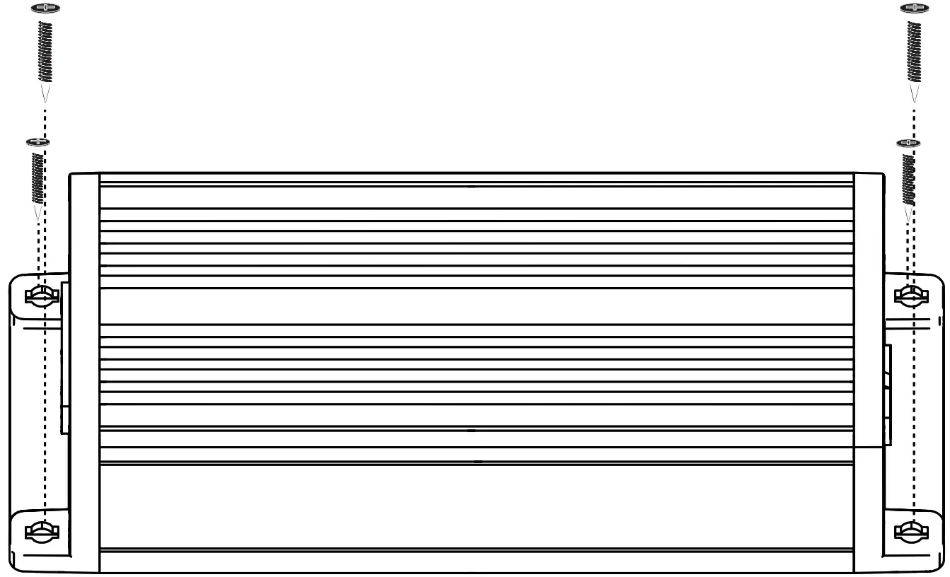
Wiring
Disconnect the vehicle’s battery to avoid an electrical short. Then connect the ground wire to the amplifier. Make the ground wire short, 24” (60cm) or less, and connect it to a paint-and-corrosion-free, solid, metal area of the vehicle’s chassis. Adding an additional ground wire of this same gauge (or larger) between the battery’s negative post and the vehicle chassis is recommended. Keep the audio signal cable away from factory wiring harnesses and other power wiring. If you need to cross this wiring, cross it at a 90 degree angle.
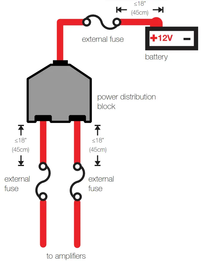
The fuse should be within 18” (45cm) of the battery and in-line with the power cable, which is connected to your amplifier. If you ever need to remove the amplifier from the vehicle after it has been installed, the ground wire should be the last wire disconnected from the amplifier–just the opposite as when you installed it. The KEY amplifier is capable of using the wiring directly from your head unit, but for best results it is recommended you use power and ground wiring from the vehicle’s battery and chassis. KICKER recommends 8 gauge wire.
| Model | External Fuse (sold separately) | Power/Ground Wire | KICKER Wiring Kit |
| KEY500.1 | 60 Ampere | 8 Gauge | PK8, CK8 |
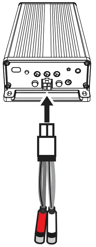
If needed, cut off the RCA connections to use hi-level input.
For multiple amplifier installations where distribution blocks are used, each amplifier should have its proper-rated fuse, or breaker, installed between the amplifier and the distribution block within eighteen inches of the block, or on the distribution block if it provides for fusing. The primary power wire should also be fused between the battery and distribution block, within eighteen inches of the battery’s positive terminal, with a fuse or breaker rated at least to the sum of the individual amplifier’s fuse values, but doesn’t exceed the capacity of your wiring.
Operation
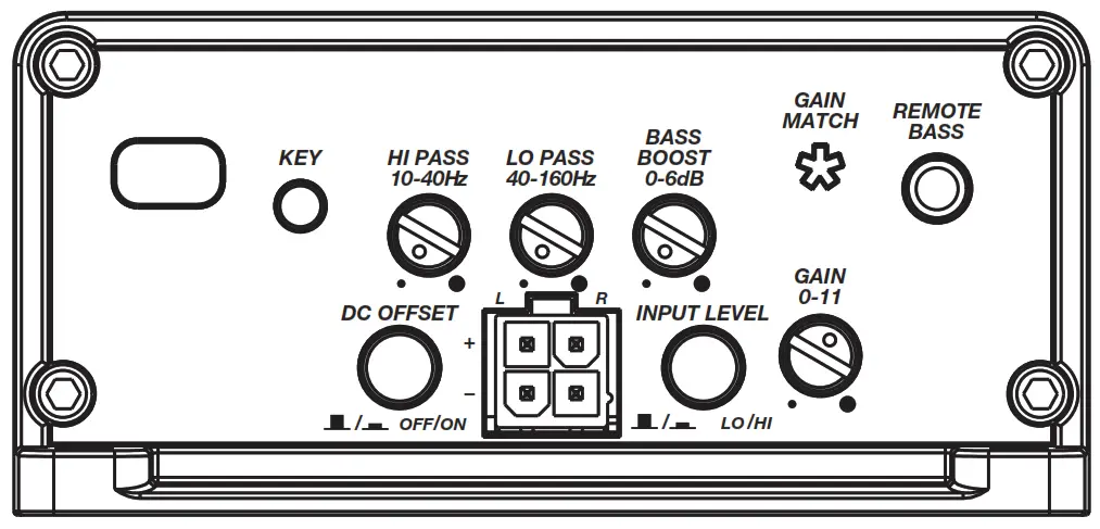
Features
DC OFFSET: The KEY500.1 automatic turn-on mode uses DC Offset detection, which can be selected on the end panel. Using the DC Offset mode causes the REM wire to have +12V out for turning on additional amplifiers. DC Offset turn-on can only be used if speaker-level (hi-level) audio inputs are being used. The DC offset mode detects a 3V DC offset on the speaker wires when the source unit has been turned on.
INPUT LEVEL: The RCA inputs are capable of receiving either Hi or Low-level signals from your source unit. If the only output available from your source unit is a Hi-Level signal, simply press in the Input Level switch on the amplifier. Refer to the wiring section of this manual for additional instructions.
Input Gain Control with Gain Matching: The input gain control is not a volume control. It matches the output of the source unit to the input level of the amplifier and features Gain Matching to prevent clipping the input. Use the KEY500.1 Gain Match track from www.KICKER.com/test-tones with the automatic to reach the most accurate and best-performing settings.
HI-PASS: Use the HI-PASS knob of the amplifier to set the internal high-pass crossover from 10–40Hz.
LO-PASS: Use the LO-PASS knob of the amplifier to set the internal low-pass crossover from 40–160Hz.
BASS BOOST: The variable bass boost control on the side of the amplifier is designed to give you increased output, 0–6dB, at 40Hz. The setting for this control is subjective. If you turn it up, you must readjust the input gain control to avoid clipping the amplifier.
REMOTE BASS: With the optional CXARC remote bass level control, you have the ability to control the output level of the amplifier remotely. To surfacemount the remote bass level control, simply screw the remote to the chosen location, then run the cable from the controller to the “Remote Bass” jack on the amplifier panel.
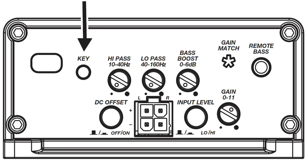
KEY Auto Setup
The KEY Activation Button is a multi-function button that will begin the Auto Setup process, enter Gain Match Mode, toggle between Auto Setup optimized audio and the original audio once the Auto Setup process has been completed, or clear previous Auto Setup settings.
Make sure active noise cancellation and active noise enhancement are disabled beforehand. You will need to load a source for the KEY500.1 test tracks from your head unit, whether CD, MP3, AUX, Bluetooth, USB etc. Uncompressed audio is recommended for best results, as this will ensure full amplitude across the frequency spectrum. Visit https://www.kicker.com/test-tones or the KEY500.1 product page and download both the “Key500.1 Gain Match” and the “Key500.1 Sweep” tracks, then proceed with the following steps.
Gain Match: Turn the source unit up to about 3/4 volume or just before the output starts to clip. (if the source unit goes to 30, turn it to 23). Press and hold the KEY button for 3 seconds until the gain match LED flashes quickly 3 times. Start the “Key500.1 Gain Match” track (The amplifier mutes its outputs during the Setup process so there will be no sound from the amplifier during setup). With the gain knob all the way down, slowly turn the input gain up (clockwise) until you see the Gain Match LED light up, then turn it down until the LED no longer flashes. Once the gain has been set, stop the Gain Match track and quickly press the KEY button to exit Gain Match Mode.
KEY Algorithm: You are now ready to start running the KEY algorithm. Press and hold the KEY button for 5 seconds until the Gain Match LED slowly flashes, then release the button. Start the “Key500.1 Sweep” track. While the KEY algorithm is running the Gain match LED will flash slowly. This process will take about 1.5 minutes. After the sweep track finishes, pause the audio. The Gain match LED will go dark while it is calculating the corrections. This takes about 30 seconds. If the algorithm runs through successfully the Gain Match LED will begin to flash rapidly for 1.5 seconds. If the algorithm fails, the Gain Match LED will go solid. In the event of a failure, you will need to short press the KEY button to exit the KEY Setup. See the manual for a troubleshooting guide if the algorithm fails.
After the algorithm has been run successfully you can do a single button press of the Key button to A/B the Key audio output in original and corrected form. A single flash indicates corrections are ON, and a double flash indicates corrections are OFF. To reset the KEY algorithm, press and hold the programming button 10 seconds. The Gain Match LED will flash 5 times indicating the KEY Algorithm has been reset.
CXARC Remote Bass
Installation
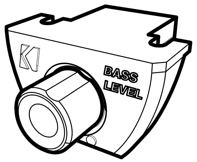
Surface-mount the CXARC remote using the supplied screws.
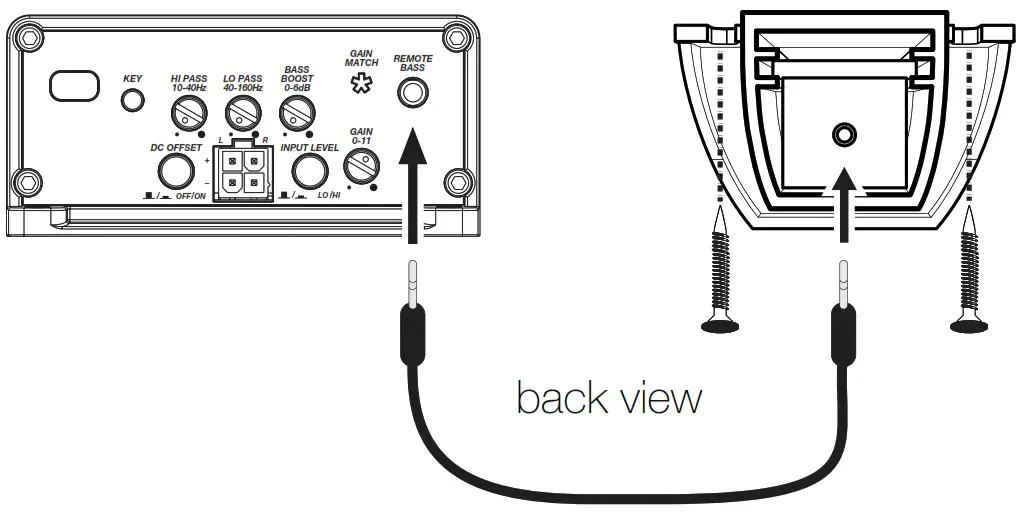 Remote cable passes audio; do not run cable parallel to power wires.
Troubleshooting
If your amplifier does not appear to be working, check the obvious things first such as blown fuses, poor or incorrect wiring connections, incorrect setting of crossover switch and gain controls, etc. There are Power (PWR) & Protection (PRT) LEDs on the side panel of your KICKER KEY series amplifier. Depending on the state of the amplifier and the vehicle’s charging system, the LEDs will glow either green or red. When the green LED is lit, this indicates the amplifier is turned on and no trouble exists.
Green LED off, no output?With a Volt Ohm Meter (VOM) check the following:
![]() +12 volt power terminal (should read +12V to +16V)
+12 volt power terminal (should read +12V to +16V) ![]() Remote turn-on terminal (should read +12V to +16V)
Remote turn-on terminal (should read +12V to +16V) ![]() Check for reversed power and ground connections
Check for reversed power and ground connections ![]() Ground terminal, for proper conductivity.
Ground terminal, for proper conductivity.
Green LED on, no output? Check the following: ![]() RCA connections
RCA connections ![]() Test speaker outputs with a “known” good speaker.
Test speaker outputs with a “known” good speaker. ![]() Substitute source unit with a “known” good source unit.
Substitute source unit with a “known” good source unit. ![]() Check for a signal in the RCA cable feeding the amplifier with the VOM meter set to measure “AC” voltage.
Check for a signal in the RCA cable feeding the amplifier with the VOM meter set to measure “AC” voltage.
Red (PRT) LED flickering with loud music? The red (PRT) LED indicates low battery voltage. Check all the connections in your vehicle’s charging system. It may be necessary to replace or charge your vehicle’s battery or replace your vehicle’s alternator.
Red (PRT) LED on, no output? ![]() Amplifier is very hot = thermal protection is engaged. Test for proper impedance at the speaker terminals with a VOM meter (see the diagrams in this manual for minimum recommended impedance and multiple speaker wiring suggestions). Also check for adequate airflow around the amplifier.
Amplifier is very hot = thermal protection is engaged. Test for proper impedance at the speaker terminals with a VOM meter (see the diagrams in this manual for minimum recommended impedance and multiple speaker wiring suggestions). Also check for adequate airflow around the amplifier. ![]() Amplifier shuts down only while vehicle is running = voltage protection circuitry is engaged. Voltage to the amplifier is not within the 6–16 volt operating range. Have the vehicle’s charging and electrical system inspected.
Amplifier shuts down only while vehicle is running = voltage protection circuitry is engaged. Voltage to the amplifier is not within the 6–16 volt operating range. Have the vehicle’s charging and electrical system inspected. ![]() Amplifier will only play at low volume levels = short circuit protection is engaged. Check for speaker wires shorted to each other or to the vehicle chassis. Check for damaged speakers or speaker(s) operating below the minimum recommended impedance.
Amplifier will only play at low volume levels = short circuit protection is engaged. Check for speaker wires shorted to each other or to the vehicle chassis. Check for damaged speakers or speaker(s) operating below the minimum recommended impedance.
GAIN MATCH LED on? Input signal overdrive or gain set too high: Reduce the gain or the strength of the input signal.
No or low output? ![]() Check the balance and fader controls on source unit.
Check the balance and fader controls on source unit. ![]() Check the RCA (or speaker input) and speaker output connections.
Check the RCA (or speaker input) and speaker output connections. ![]() Check the volume level on your source unit, to include the volume level of any connected phones or MP3 players.
Check the volume level on your source unit, to include the volume level of any connected phones or MP3 players.
Alternator noise-whining sound with engine’s RPM? ![]() Check for damaged RCA (or speaker input) cable
Check for damaged RCA (or speaker input) cable ![]() Check the routing of RCA (or speaker input) cable
Check the routing of RCA (or speaker input) cable ![]() Check the source unit for proper grounding
Check the source unit for proper grounding ![]() Check the gain settings and turn them down if they are set too high.
Check the gain settings and turn them down if they are set too high.
CAUTION: When jump-starting the vehicle, be sure that connections made with jumper cables are correct. Improper connections can result in blown amplifier fuses as well as the failure of other critical systems in the vehicle.
If you have more questions about the installation or operation of your new KICKER product, see the Authorized KICKER Dealer where you made your purchase. For more advice on installation, click on the SUPPORT tab on the KICKER homepage, www.KICKER.com. Choose the TECHNICAL SUPPORT tab, choose the subject you are interested in, and then download or view the corresponding information. Please E-mail or call Technical Services (405) 624-8583 for unanswered or specific questions.
Warranty
When purchased from an Authorized KICKER Dealer, KICKER warrants this product to be free from defects in material and workmanship under normal use for a period of TWO (2) YEARS from date of original purchase with receipt. If this product is identified as “Refurbished” or “B Goods”, the warranty is limited to a period of THREE (3) MONTHS from the date of original purchase. In all cases, you must have the original receipt. Should service be necessary under this warranty for any reason due to manufacturing defect or malfunction during the warranty period, KICKER will repair or replace (at its discretion) the defective merchandise with equivalent merchandise. Warranty replacements may have cosmetic scratches and blemishes. Discontinued products may be replaced with more current equivalent products. This warranty is valid only for the original purchaser and is not extended to owners of the product subsequent to the original purchaser. Any applicable implied warranties are limited in duration to a period of the express warranty as provided herein beginning with the date of the original purchase at retail, and no warranties, whether express or implied, shall apply to this product thereafter. Some states do not allow limitations on implied warranties; therefore, these exclusions may not apply to you. This warranty gives you specific legal rights; however, you may have other rights that vary from state to state.
WHAT TO DO IF YOU NEED A WARRANTY OR SERVICE:Defective merchandise should be returned to your local Authorized Stillwater Designs (KICKER) Dealer for warranty service. Assistance in locating an Authorized Dealer can be found at www.KICKER.com or by contacting Stillwater Designs directly. You can confirm that a dealer is authorized by asking to see a current authorized dealer window decal.If it becomes necessary for you to return defective merchandise directly to Stillwater Designs (KICKER), call the KICKER Customer Service Department at (405) 624-8510 for a Return Merchandise Authorization (RMA) number. Package only the defective items in a package that will prevent shipping damage, and return to:
Stillwater Designs, 3100 North Husband St, Stillwater, OK 74075
The RMA number must be clearly marked on the outside of the package. Please return only defective components. The return of functioning items increases your return freight charges. Nondefective items will be returned freight-collect to you. For example, if a subwoofer is defective, only return the defective subwoofer, not the entire enclosure. Include a copy of the original receipt with the purchase date clearly visible, and a “proof-of-purchase” statement listing the Customer’s name, Dealer’s name and invoice number, and product purchased. Warranty expiration on items without a proof of purchase will be determined from the type of sale and manufacturing date code. Freight must be prepaid; items sent freight collect, or COD, will be refused.
WHAT IS NOT COVERED?
This warranty is valid only if the product is used for the purpose for which it was designed. It does not cover:
- Damage due to improper installation
- Subsequent damage to other components
- Damage caused by exposure to moisture, excessive heat, chemical cleaners, and/or UV radiation
- Damage through negligence, misuse, accident or abuse. Repeated returns for the same damage may be considered abuse
- Any cost or expense related to the removal or reinstallation of product
- Speakers damaged due to amplifier clipping or distortion
- Items previously repaired or modified by any unauthorized repair facility
- Return shipping on non-defective items
- Products with tampered or missing barcode labels
- Products with tampered or missing serial numbers
- Products returned without a Return Merchandise Authorization (RMA) number
- Products purchased from an UNAUTHORIZED dealer
- Freight Damage
- The cost of shipping product to KICKER
- Service performed by anyone other than KICKER
 report this ad
HOW LONG WILL IT TAKE?KICKER strives to maintain a goal of a one-week turnaround for all electronics (amplifiers, crossovers, equalizers, etc.) returns. Delays may be incurred if lack of replacement inventory or parts is encountered. Failure to follow these steps may void your warranty. Any questions can be directed to the KICKER Customer Service Department at (405) 624-8510. Contact your International KICKER dealer or distributor concerning specific procedures for your country’s warranty policies.
References
[xyz-ips snippet=”download-snippet”]