![]()
Owner’s ManualDSP-Powered Line Output Converter
Overview
IMPORTANT SAFETY WARNINGPROLONGED CONTINUOUS OPERATION OF AN AMPLIFIER, SPEAKER, OR SUBWOOFER IN A DISTORTED, CLIPPED, OR OVER-POWERED MANNER CAN CAUSE YOUR AUDIO SYSTEM TO OVERHEAT, POSSIBLY CATCHING FIRE AND RESULTING IN SERIOUS DAMAGE TO YOUR COMPONENTS AND/OR VEHICLE. AMPLIFIERS REQUIRE UP TO 4 INCHES (10CM) OPEN VENTILATION. SUBWOOFERS SHOULD BE MOUNTED WITH AT LEAST 1 INCH (2.5CM) CLEARANCE BETWEEN THE FRONT OF THE SPEAKER AND ANY SURFACE. KICKER PRODUCTS ARE CAPABLE OF PRODUCING SOUND LEVELS THAT CAN PERMANENTLY DAMAGE YOUR HEARING! TURNING UP A SYSTEM TO A LEVEL THAT HAS AUDIBLE DISTORTION IS MORE DAMAGING TO YOUR EARS THAN LISTENING TO AN UNDISTORTED SYSTEM AT THE SAME VOLUME LEVEL. THE THRESHOLD OF PAIN IS ALWAYS AN INDICATOR THAT THE SOUND LEVEL IS TOO LOUD AND MAY PERMANENTLY DAMAGE YOUR HEARING. PLEASE USE COMMON SENSE WHEN CONTROLLING VOLUME.The revolutionary KEYLOC is not your standard LOC. In addition to providing you with a preamp-level signal for use with aftermarket amplifiers, the KEYLOC revolutionizes audio integration into OEM systems. The KEYLOC does this with a tuning process that automatically detects the available frequency response from the input signal and, if desired, corrects factory EQ settings, creating a linear signal. It also detects and defeats factory settings like All-Pass filters and time delay.This DSP-powered mobile audio multitool strips the factory audio of coloration while attenuating and maximizing available frequencies to achieve a full range signal. This allows you to get to the important work of tuning your audio system with the ease and confidence that come from knowing you’re working with a clean signal.With a simple, step-by-step detection and calibration process, your aftermarket installs are about to get a lot easier, with results you can hear!
Specifications
| Model: | KEYLOC |
| Rated Output per channel 1KHz @ 14.4V, ≤ 1% THD+N | 10V |
| Length [in, cm] | 5-1/2, 14 |
| Height [in, cm] | 1-3/8, 3.5 |
| Width [in, cm] | 2-3/4, 7.1 |
| Frequency Response | 20Hz–20kHz |
| Signal-to-Noise Ratio | >90dB, A-weighted, re: rated power |
| Input Sensitivity | Lo: 250mV–10V – Fixed 60Ω Load Hi: 1V–40V |

Before You Begin
There are multiple audio tracks you will need to download from Kicker.com to get the most out of the KEYLOC. Please use the following link https://www.kicker.com/test-tones to download these tracks:
- Full test
- Gain Match
- Noise floor
Optional Tracks:
- Pink Noise
- 20Hz – 20kHz sweep track
Features
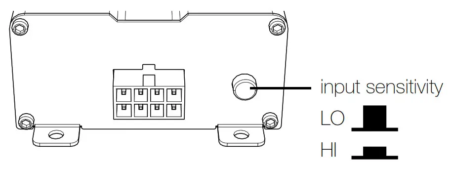
The KEYLOC is a 2-channel DSP-based active line output converter with the following features.Automatic Turn-on: DC offset remote input turn-on, and remote output turn-on (100mA) to turn on other products.Frequency Response Correction: Smooths frequency response of two channels from your source unit via EQ correction. It can fix EQs with Qs ranging from 0.5-10 with up to +/- of 12dB of boost or cut.Factory Time Delay Defeat: Ranging from .06mS – 10mS, the algorithm is accurate down to .06mS.ALL-Pass Filter Defeat: The KEYLOC can correct up to three all-pass filters on one channel. The All-pass filters can have a Q ranging from 0.5–3.5,as long as they do not interact with the other All-Pass filter’s phase.Passive Frequency Detection: Before running the KEYLOC setup process, it is in passive frequency detection mode. You can use this model to detect what band of frequencies are available on the given speaker outputs that the KEYLOC is connected to.Input Level: The speaker inputs are capable of receiving either HI or LO level signals from your source unit. When using a HI-Level signal, simply Press the Input Level switch on the amplifier to HI.
Installation
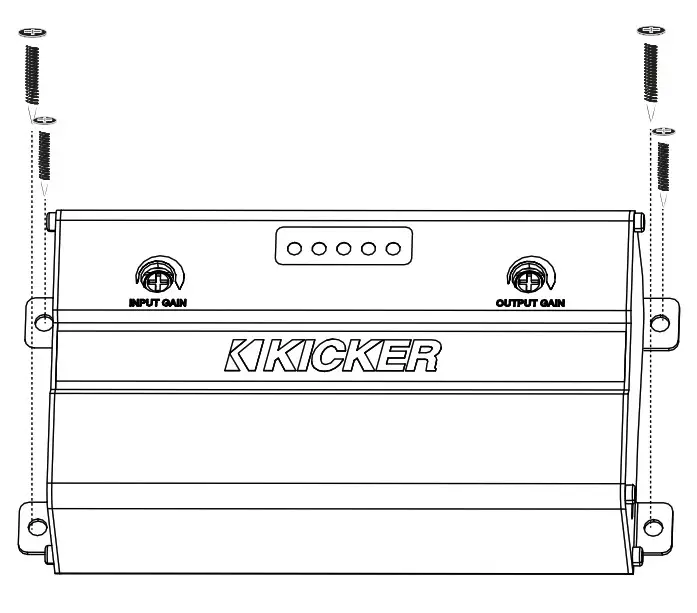
Mounting
Choose a structurally sound location to mount the KEYLOC. Make sure there are no items behind the area where the screws will be driven. If possible, mount the KEYLOC behind the dash or in the climate-controlled passenger compartment. Drill four holes using a 7/64” (3mm) bit and use the supplied #8 screws to mount.
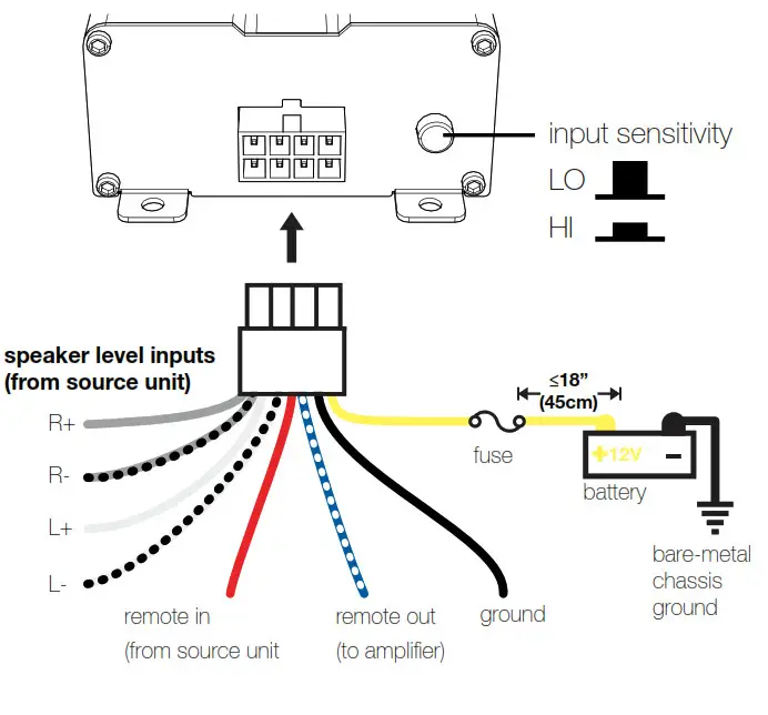
Wiring
Disconnect the vehicle’s battery to avoid an electrical short. Then connect the ground wire to the KEYLOC. Make the ground wire short, 24” (60cm) or less, and connect it to a paint-and-corrosion-free, solid, metal area of the vehicle’s chassis. Install a 2A fuse between the KEYLOC and the power source. The fuse should be within 18” (45cm) of the power source and in-line with the harness’ yellow power cable, which is connected to the KEYLOC. Keep the audio signal cable away from factory wiring harnesses and other power wiring. If you need to cross this wiring, cross it at a 90-degree angle. Connect your source unit’s speaker outputs to the KEYLOC speaker inputs. When interfacing into factory speaker wires it is recommended to splice and solder, if you need to use wiretaps make sure you use properly sized wiretaps to ensure a solid connection.
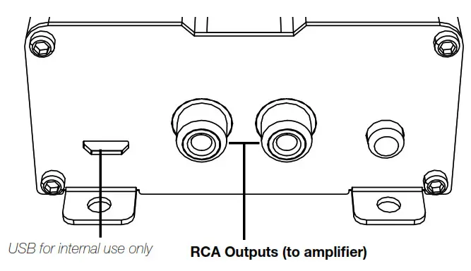
Connect the preamp-level RCA outputs to your amplifier.
Testing for DC Offset: If your head unit has a remote output you can connect this to the remote input of the KEYLOC. If your head unit does not have a remote output, the KEYLOC can use the DC offset that is present on the speaker outputs of most factory head units. To measure for DC offset, connect your voltmeter’s negative lead to the vehicle’s chassis ground, the positive lead to the speaker wire you are interfacing with, and set the voltmeter to ‘DC volts’. When the source unit you’re using is on, you should see DC voltage from between 2.5V–6V. The KEYLOC will sense this DC offset to turn on, and output 12V on its own remote output (up to 100mA) to turn on your aftermarket amplifier(s). If tools are unavailable, please see page 16.
This simple test will determine if you need to connect the Remote Turn-On lead to a switched +12V DC source, or if you can depend on DC Offset Turn-On to turn the KEYLOC on and off.The radio must be on (a low volume setting is fine for this test). Set your voltmeter to measure DC Voltage. Connect one of your voltmeter’s test probes to a speaker lead and the other probe to the chassis ground.
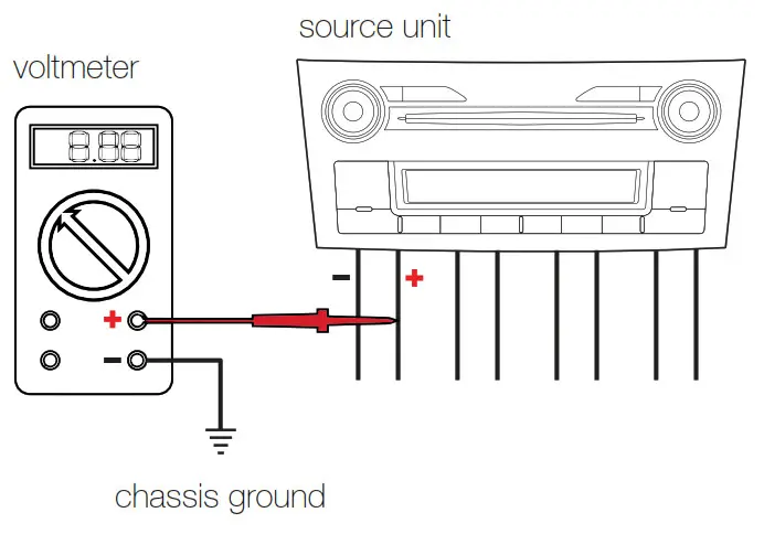 There should be a DC voltage present on your speaker lead. The DC voltage must be between 2.5 and 6V DC to be able to turn the KEYLOC on. If it is the red Remote Turn-On wire does not need to be used. The KEYLOC will sense this DC offset to turn on, and output +12V on its remote utput (up to 100mA) to turn on your aftermarket amplifier(s).IMPORTANT: If the DC Voltage you measure is less than 2.5V, the KEYLOC DC offset turn-on function will not operate reliably. If this is the case, you will need to find a +12V DC switched circuit in the vehicle and connect the RED remote turn-on wire to that switched circuit.
Setup
Passive Frequency Detection is ready when the KEYLOC first powers up. We recommend you perform this test right away to confirm the wires that you’ve found have the signal you need for the given application.NOTE: If you need a full-range signal and there isn’t one available, you will have to use multiple KEYLOCs and sum their outputs together externally.To perform this test, you need the Pink Noise test track from https://www.kicker.com/test-tones. Shorter tracks will work, but longer tracks like this will give you more time to perform the test.
- Turn the INPUT gain adjustment on top of the KEYLOC all the way down.
- Turn the factory source unit volume to at least 50%.
- Play the Pink Noise test track.
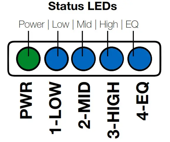
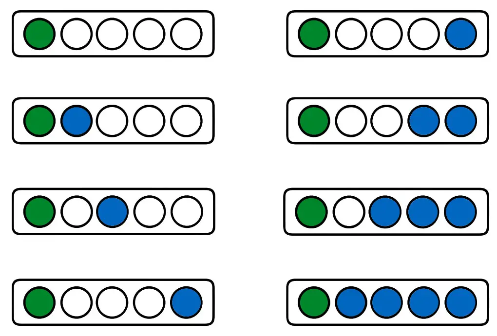
- Turn the INPUT adjustment up slowly until you see LEDs 1, 2, and/or 3 illuminate. (LED 4 will remain off) The Status LEDs will serve as a three-band RealTime Analyzer (RTA), confirming what frequencies are included with the signal into which you have tapped.
NOTE: If you see one or two LEDs on, but you have to turn the INPUT adjustment up a great deal to get the others to turn on, this means that the signal is not full-range and the KEYLOC may have difficulty restoring it to full-range. This is only a concern if the system requires a full-range signal. If you are installing a subwoofer system, it is essential that the “1-LOW” LED comes on. This indicates you have bass – but it is not essential that 2-MID or 3-HIGH LEDs come on if you are using the KEYLOC for a subwoofer-only application.
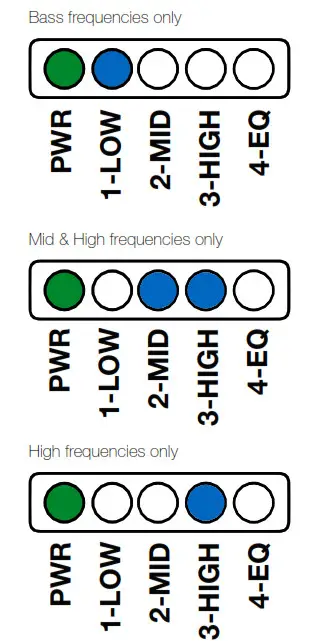
Frequency Detection
| Low | Mid | High |
| 20Hz–200Hz | 200Hz–2kHz | 2kHz–20kHz |
 Setting Input Level
 Setting Input Level
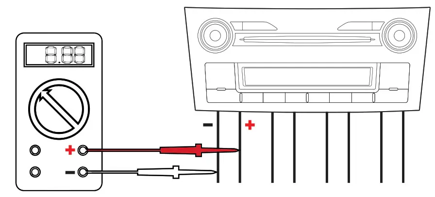
Testing the output voltage of the source unit before selecting the input level setting is highly recommended to determine whether the KEYLOCneeds to be in HI or LO level input mode. In general, if your input signal is coming from the audio source unit use the LO Level Input Sensitivity setting, or if your input signal is coming from a factory amplifier use the HI Level Input Sensitivity setting. The LO range can accept 250mV-10V. The HI range can accept 1V – 40 V. If no tools are available, please go to page 16. If you’re not sure what the output voltage is, please use the following process:Testing Audio Source Output Voltage: This will tell you whether to set the INPUT level setting switch to HI or LO. This can be done with a voltmeter as used above or an oscilloscope.To use a voltmeter, change the setting on the meter to measure AC Voltage. Connect the positive lead of the meter to the speaker + and the negative lead to the speaker –. Turn the source unit up to max volume playing a O dB sinewave test tone. Because factory source units have equalization applied to their outputs, not every frequency will have the same output voltage. Because of this, we suggest doing this test with a 20Hz – 20kHz sweep track. This track will sweep from 20Hz to 20kHz to let you find the highest voltage over the entire audio band and can be downloaded from https://www.kicker.com/test-tones.
Optional Testing for Audio Source Clipping Point with an Oscilloscope: This test will tell you where to set the volume knob of the factory source unit during the KEYLOC setup process. This can be used instead of the previous process with the voltmeter to tell you if the INPUT Level switch should be in the HI or LO setting.IMPORTANT: If the signal coming out of the factory source unit is clipping, the KEYLOC setup process will fail to correctly fix the signal!If you have an oscilloscope, use the method below to get the best results on the first try. If you do not have access to an oscilloscope, please go to Signal Restoration on page 16.NOTE: Don’t do this test with the factory speakers connected, and ensure the speaker leads are not shorted together.

- Connect your oscilloscope probes across the speaker (+) and (–) leads as shown.
- Set the oscilloscope to read AC Voltage.
- Set the tone controls in your factory source unit’s menu control to 0 or their neutral position.
- Once your test equipment is ready, play the 20Hz – 20kHz sweep track.
- Turn up the volume of the source unit until you see clipping of the waveform (this is when the tops and bottoms of the sine wave starts to be cut off).
- Turn the volume down one or two clicks from that point. Note the AC Voltage indicated, and the volume level indicated on the factory source.
- IMMEDIATELY turn down the volume to a low level.
This volume setting represents your maximum “clean” output level on the factory audio source. Use this volume setting for the correcting signal step below. Advise your customer that volume settings above this level will introduce distortion into the audio path and will not sound as clean as below this volume level.NOTE: If the voltage measured in this test is higher than 10V AC, you MUST set the input level switch to HI. If the voltage is below 1V AC, you UST set the input level switch to LO.
In the LO setting range, there is a 60Ω load applied for use with newer smart radios that shut off their outputs if they do not detect a speaker connected to the source unit. If there is a need to load a source unit that has an output voltage greater than 10V, please use the KISLOAD products instead of the KEYLOC’s built in load resistors.
Signal Restoration
Correcting Signal: This 12-step process uses the KEYLOC’s internal DSP to correct factory equalization, time delay, or phase processing. It takes between 5–10 minutes in most applications to complete. This process requires you to be able to see the Status LEDs clearly, as well as access to the INPUT and OUTPUT gain adjustments, HI/LO switch, and KEY button on the KEYLOC

IMPORTANT: To perform this step, if you have not already downloaded them you will need three tracks from www.kicker.com/test-tones:GainMatch,NoiseFloor,Fulltext
This is the order in which you will use these files, so this is the order you should use when saving them to a USB stick or burning them to an Audio CD.NOTE: There are both MP3 and WAV files available.NOTE: If you press the KEY button at the wrong time during this process, you will get an error code – all blue LEDs blinking. If this happens, press and release the KEY button to exit the process, and then start over from the beginning.

NOTE: At the beginning of this process, the outputs of the KEYLOC are muted. At the end of this process, the KEYLOC will begin to pass audio.Turn the OUTPUT gain adjustment down!
- Turn down the INPUT GAIN and OUTPUT GAIN adjustments – fully counterclockwise.
- Set the Factory Source Unit’s volume knob – set it to the maximum clean volume level that is not clipped as confirmed in the previous steps. If you didn’t test for clipping, set radio volume to 75%.
- In the factory source unit’s audio menu, confirm the Bass and Treble and Balance and Fader controls, and any Equalizer controls, are all set to 0 or their neutral position. Turn off any settings such as speed-compensated volume, or any audio processing you don’t intend to use with the upgraded system.
- Press and Hold the KEY button for 8 seconds. The LEDs will sweep from 1 to 4, and then illuminate 2, 1+2, 1+2+3, and then 1-4 together.
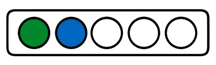
- Release the KEY button. LED 1 will illuminate; LED 2-4 will turn off. You are now in the KEYLOC’s Gain match mode.
- Play the GainMatch track.
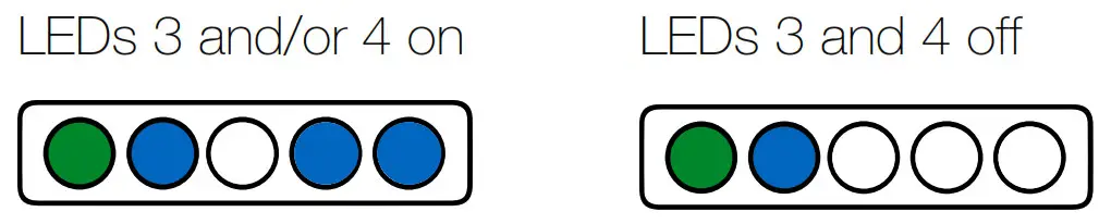
- Slowly turn the INPUT gain knob clockwise until either LED 3 or 4 turns on. Once they do, slowly turn back the knob counterclockwise until both LED 3 and 4 turn off. Closely watch both LEDs for 10 seconds – they often will illuminate again, and this means you must turn the knob counterclockwise an additional amount until both LEDs remain off for a full 10 seconds. If both LEDs remain on at all times or remain off at all times regardless of the gain setting, check the position of the HI/LO button is set to the proper setting given the source unit’s output voltage. If they remain off regardless of the position of the HI/ LO button, check your connections. Once both LEDs 3 and 4 stop blinking you have properly set the INPUT sensitivity.
- Stop track: GainMatch, then play track: Noise floor
- Press the KEY Button. LED 1 will begin to blink. When the Noise floor is detected, LED1 will stop blinking and LED2 will start blinking.
- Play track: FullTest. While the track is running you will see the LEDs progress from LED1 to LED4. The Fulltext track is 22 minutes long to accommodate for many applications, however, most corrections will take between three to eight minutes. Here is what to expect during this test.a. LED 2 will be solid 10–20 seconds then (first EQ correction sweep)b. LED 3 will be solid for 30–90 seconds. (second EQ correction sweep)c. LED 4 will be solid for 30–90 seconds. (final EQ sweep)d. LED 3 and 4 will light up between 30–240 seconds (AllPass and Time delay detection)e. The LEDs will begin to flash once the KEYLOC has collected enough data and is processing the test results.
- The LEDs will sweep back and forth when the KEYLOC has completed its calculations, and audio will begin passing. Press the KEY button to exit the set-up mode.
- LED 4 will turn on to indicate the EQ correction is running. LEDs 1 – 3 will light up to indicate the available frequency ranges.
 Once both LEDs 3 and 4 stop blinking you have properly set the INPUT sensitivity.
To toggle the EQ correction ON/OFF, press the KEY button once. If LED4 is ON, EQ correction is on. If LED 4 is OFF, EQ correction is off.To reset the KEYLOC to factory: Enter the main menu by pressing and holding the KEY button for 6 seconds. You will see the LEDs sweep from 1 – 4. Release the KEY Button and LED 1 will light up. Click the KEY button until LED 3 is illuminated. Hold the KEY button until all LEDs are illuminated. Release the KEY button and the unit will restart. Your KEYLOC is now reset back to the factory.Error CodesIf the power LED and any combination of LEDs begin to blink, it indicates an error in the setup process. Press the KEY button to reset the device.LEDs 1, 2, 3, 4 – ONUnable to find the noise floor. This indicates there is too much signal, or it is too noisy. This usually happens when the Noise Floor track is not playingbefore beginning Step 7.LEDs 2, 3, 4 – or 1, 3, 4 – ONUnable to interpret frequency response. This usually indicates the input is clipping or it is too noisy.Navigating the Menu:After the Auto setup process has been completed, you’ll be able to navigate the KEYLOC menu using the KEY button and LEDs. To enter the menu, press and hold the KEY button for 4 seconds. You will see the LEDs sweep 1-4 – release the KEY button. Quick-press the KEY button to cycle through the menu options:LED1 – Allpass or Time-Delay defeat ON/OFFSolid: Time-Delay correction is active Blinking: Time-delay/all pass defeated Press and hold the KEY button for 2 seconds to toggle defeat ON/OFFLED2 – Gain Match StatusLED 2 indicates Left/Right Channel gain matching status.Solid: OnBlinking: OffLED3 – Reset KEYLOCHold the KEY button for 10 secondsLED4 – Exit the MenuHold the KEY button for 1 second to exit the menuLine-Output ConversionAfter Auto Setup is complete, use the Output Gain to match the output voltage of the KEYLOC to the input sensitivity voltage of your amplifier. If you’re not using gain match capable electronics or a voltmeter/ voltmeter, listening for audible distortion is always the next best way to set your gain.Sending a high voltage signal to your amplifier when possible is always the best practice. To set the Output Gain, turn the KEYLOC Output Gain and the input gain of your amplifier all the way down. With audio playing, turn the KEYLOC Output Gain up until you have achieved your desired volume level or you begin to hear distortion, then reduce the Output Gain until it’s gone.
 report this ad
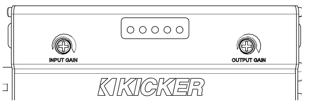
Troubleshooting
If the KEYLOC becomes frozen or stuck during algorithmic calculation, does not appear to be working, or gives an error code, check the obvious things first such as blown fuses, poor or incorrect wiring connections, incorrect setting of gain controls, etc.Tips for SETUP:
- If you have issues getting a smoothed EQ response on an Real-Time Analysis, go back and verify that the INPUT GAIN match of the KEYLOC is set correctly. If there are tall peaking filters in your analysis, it can take two or three sweeps of the GAIN MATCH track to ensure proper gain matching (It’s recommended to wait 10 – 15 seconds to make sure the gain match LEDs are not flashing). If there’s still an issue where the frequency response is not being fully corrected, it is suggested to turn the input gain down ¼ of a turn and run the KEYLOC setup process again.
- If the issue persists, it is very likely that the output of your source unit is being clipped. Use the GAIN SWEEP track and an oscilloscope on the output of your source unit to verify that the signal coming from the source unit is not clipping. If there is any clipping, slowly turn down the volume on the source unit until all clipping is eliminated.
- In most aftermarket systems in which you will not be using a fully active DSP after the KEYLOC in the signal chain, you will likely want to turn off the All pass/Time delay defeat for the best stereo imaging. See page 20.
- To keep the noise floor (hiss) low, we have designed the KEYLOC to not add more than 18db of gain to any one frequency. In most applications, this should correct the frequency response to a nearly linear response of +/1.5dB in the frequency bands available.
- During the KEY process, if you accidentally push the KEY button before playing the NOISE FLOOR track, the KEYLOC will error out and all LEDs will begin to flash. You must then press the KEY button to exit the KEY process. Re-enter the KEY process to start again.
No power? With a Volt Ohm Meter (VOM) check the following: 1+12 volt power terminal (should read +12V to +16V) 2 Remote turn-on terminal (should read +12V to +16V) 3Check for reversed power and ground connections 4Ground terminal, for proper conductivity.Power on, no signal? Check the following: 1RCA connections 2 Test audio source signal, either with a “known good” output device or other means.No or low output? 1 Check the balance and fader controls on source unit. 2 Check the RCA (or speaker input) and speaker output connections.3 Check the volume level on your source unit, to include the volume level of any connected phones or MP3 players.KEYLOCK frozen or stuck in the operating procedure? 1 Cycle the power 2 Reset the remote 3Reset the KEYLOC Alternator noise-whining sound with engine’s RPM? 1 Check for damaged RCA (or speaker input) cable 2 Check the routing of RCA (or speaker input) cable 3 Check the source unit for roper grounding 4 Check the gain settings and turn them down if they are set too high.CAUTION: When jump-starting the vehicle, be sure that connections made with jumper cables are correct. Improper connections can result in blown fuses as well as the failure of other critical systems in the vehicle. If you have more questions about the installation or operation of your new KICKER product, see the Authorized KICKER Dealer where you made your purchase. For more advice on installation, click on the SUPPORT tab on the KICKER homepage, www.KICKER.com. Choose the TECHNICAL SUPPORT tab, choose the subject you are interested in, and then download or view the corresponding information. Please E-mail [email protected] or call Technical Services (405) 624-8583 for unanswered or specific questions.
References
[xyz-ips snippet=”download-snippet”]