
KX.2-SERIES AMPLIFIERSOWNER’S MANUAL
KXA400.2 | KXA1200.2 | KXA400.4
IMPORTANT SAFETY WARNINGPROLONGED CONTINUOUS OPERATION OF AN AMPLIFIER, SPEAKER, OR SUBWOOFER IN A DISTORTED, CLIPPED OR OVER-POWERED MANNER CAN CAUSE YOUR AUDIO  SYSTEM TO OVERHEAT, POSSIBLY CATCHING FIRE AND RESULTING IN SERIOUS DAMAGE TO YOUR COMPONENTS AND/OR VEHICLE. AMPLIFIERS REQUIRE UP TO 4INCHES (10CM) OPEN VENTILATION. SUBWOOFERS SHOULD BE MOUNTED WITH AT LEAST 1 INCH (2.5CM) CLEARANCE BETWEEN THE FRONT OF THE SPEAKER AND ANY SURFACE.
PERFORMANCE
INSTALLATIONMounting: Choose a structurally sound location to mount your KICKER amplifi er. Make sure there are no items behind the area where the screws will be driven. Choose a location that allows at least 4” (10cm) of open ventilation for the amplifi er. If possible, mount the amplifi er in the climate-controlled passengercompartment. Drill four holes using a 7/64” (3mm) bit and use the supplied #8 screws to mount the amplifi er.
Wiring:
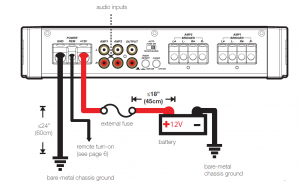
Disconnect the vehicle’s battery to avoid an electrical short. Then, connect the ground wire to the amplifi er. Make the ground wire short, 24” (60cm) or less, and connect it to a paint-and-corrosion-free, solid, metal area of the vehicle’s chassis. Adding an additional ground wire of this same gauge (or larger) between the battery’s negative post and the vehicle chassis is recommended.
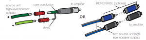
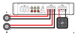
The KX amplifi er’s RCA inputs will receive either high or low level signals from your car stereo’s source unit. A high-level signal can be run from the source unit’s speaker outputs to the stereo RCA input on the end panel of the amplifi er using the KICKER KISL as shown. Alternatively, the signal can be delivered tothe amplifi er using the low-level RCA outputs on the source unit. Keep the audio signal cable away from factory wiring harnesses and other power wiring. If you need to cross this wiring, cross it at a 90 degree angle.
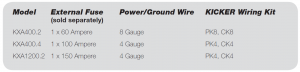
Install a fuse within 18” (45cm) of the battery and in-line with the power cable connected to your amplifi er.If you ever need to remove the amplifi er from the vehicle after it has been installed, the ground wire should be the last wire disconnected from the amplifi er–just the opposite as when you installed it.
POWER WIRING
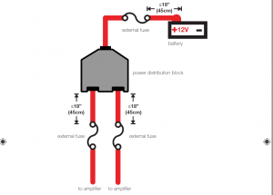
For multiple amplifier installations where distribution blocks are used, each amplifier should have its proper-rated fuse, or breaker, installed between the amplifi er and the distribution block within eighteeninches of the block, or on the distribution block if it provides for fusing. The primary power wire should also be fused between the battery and distribution block, within eighteen inches of the battery’s positiveterminal, with a fuse or breaker rated at least to the sum of the individual amplifi er’s fuse values, butndoesn’t exceed the capacity of your wiring.
KICKER will now provide a three-year warranty with all KXASeriesAmplifi er purchases paired with a qualifying KICKERInstallation Kit* .
This extends the standard warranty by an additional year. Amplifier and Kit must be purchased from an Authorized KICKER Dealer.
KICKER KX amplifier success is currently at an unheard-of rate, making the extended warranty program even more beneficial to you. Using poor-quality, under-spec wiring kits will impede KX amplifier performance.
A superior-quality KICKER installation Kit is guaranteed to extend the life of KX amplifiers.
The new extended warranty applies only to KICKER amplifi ers and accessories sold to consumers by Authorized KICKERDealers in the United States of America or its possessions. It also only applies to the original purchaser of KICKER amplifi ers and accessories. One warranty extension per amplifi er is allowed regardless of the number of amplifi er installation kits purchased. This program does not apply to “B”-stock product or factory-refurbished product.This offer is for a limited time, so see your local Authorized KICKER Dealer soon for details.
*U.S.A. Only | EE.UU. solamente | Nur USA | Les USA Seulement
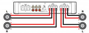
FOUR CHANNEL OPERATIONminimum impedance of 2 ohm
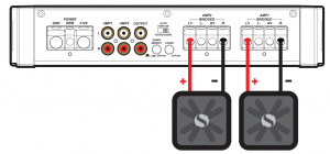
BRIDGED OPERATION (MONO)minimum impedance of 4 ohms
STEREO-AND-MONO-SIMULTANEOUSLY (SAMS) OPERATIONminimum impedance of 4 ohms bridged (mono) and 2 ohm per channel stereo
OPERATION
Mini-USB for internal use only; do NOT remove or tamper. KICKER is not responsible for any damage to equipment resulting from connections made to this port.
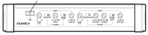
Automatic Turn-On Selection: The KX series offers three different automatic turn-on modes that can be selected on the end panel; +12V, DC Offset, and Audio. Using either the DC Offset or Audio modem causes the REM terminal to have +12V out for turning on additional amplifi ers.
- Remote Turn-On: Set the switch to +12V to use the remote turn-on lead from your source unit. Run 18 gauge wire from the Remote Turn-On Lead on your source unit to the terminal labeled REM between theamplifier’s positive and negative power terminals. This is the preferred automatic turn-on method.
- DC Offset Turn-On: If Remote Turn-On is not an option, the next best setting is DC Offset. The DC Offset mode detects a 3V DC offset from the HI-Level speaker outputs when the source unit has been turned on.
- Signal Sense Turn-On: The Audio setting is the fi nal alternative for Automatic turn-on. This is a Signal Sense turn-on method that detects the incoming audio signal from your source unit and automatically turns on theamp. This turn-on method will not work properly if the input gain control is not set appropriately.
Radio Detect:
The RCA inputs on KICKER KX amplifi ers are capable of receiving either Hi or Low-level signals from your source unit. If you are using Hi-Level inputs, but your source unit cannot detect an audio system present or refuses to play audio out of one or more speakers, you may need to set Radio Detectto ON. This will activate a load resistor at the amplifi er’s inputs and tell the source unit there are speakers present. Do NOT use Radio Detect if you are using a Low-Level input signal; doing so will greatly reduce theinput signal.
Fader Switch (KXA400.4 only):
Depress the fader switch if you are running two sets of inputs (frontand rear for example) to the amplifi er. Leave the fader switch OFF if you want to drive all channels from a single stereo input.
Input Gain Control with Gain Matching:
The input gain control is not a volume control. It matches theoutput of the source unit to the input level of the amplifi er and features Gain Matching to prevent clipping the input. For a quick setup, turn the source unit up to about 3/4 volume (if the source unit goes to 30, turn it to25). KICKER recommends using the test tones at www.kicker.com/support/ to reach the most accurate and best performing settings. Next, slowly turn (clockwise) the gain on the amplifi er up until you see the Gain LEDlight up or hear audible distortion, then turn it down a little. If the GAIN knob’s backlight comes on, the input is still clipping. For full instructions on Gain Matching, please see the next page.
Crossover Switches with Frequency Multiplier:
Use the XOVER switches on the end panel of the amplifi er to set the internal crossovers of AMPS 1 & 2 to OFF, HI-PASS, LO-PASS, or BAND-PASS (AMP 2 only). When the switch is set to OFF, a full bandwidth signal will be amplifi ed. Set the switch to HP if you want the amplifi er’s internal crossover to serve as a high-pass fi lter. Set the switch to LP if youwant the amplifi er’s internal crossover to serve as a low-pass fi lter. Set the switch to BP when a specifi c frequency range is required. Never change the crossover switches with the audio system on!
Set the 1X/10X frequency multiplier switch to the setting that is appropriate for your application. A setting of 10X will set the range of the AMP 1 crossover to 100–5,000Hz, and the crossover of AMP 2 to 400–5,000Hz.
KICK EQ Bass Boost Control:
The variable bass boost control on the side of the amplifi er is designedto give you increased output, 0–18dB, at 40Hz. The setting for this control is subjective. If you turn it up, you must readjust the input gain control to avoid clipping the amplifi er.
GAIN MATCHINGIn any audio system, the goal is to reach maximum input and output levels without distortion or clipping.The engineers at KICKER have taken the guesswork, and hassle, out of matching the output voltage of your source unit to the amplifi er with the Gain Matching feature. To begin, you’ll need to download theKICKER test tones from www.kicker.com/test-tones. The following fi les are available in MP3 and WAVformats: 1kHz @ 0dBFS, 50Hz @ 0dBFS, 1kHz @ -10dBFS, 50Hz @ -10dBFS, 1kHz @ -5dBFS, 50Hz @ -5dBFSThese test tones are sine waves meant to provide a consistent signal for the KX amplifi er to reference. The different recording levels are designed to give you the perfect gain match for your application.
0dBFS: Designed for audiophile applications to give you distortion free audio output with the most dynamic range
-5dBFS: Designed for normal/daily applications, there will be less dynamic range but higher potential audio output levels. With this set up you can get some occasional clipping from the amplifi er.
-10dBFS: Designed only for Subwoofer applications, there will be less dynamic range but higher potential audio output levels. With this set up you can get some clipping from the amplifier.
Afterwards, use the following procedure to accurately Gain Match your amplifier(s):
- Disconnect the speakers from the KX amplifier.
- Set all EQ and crossover settings to fl at on your source unit.
- Play the downloadable fi le from KICKER.com
- Turn the source unit up to 3/4 volume.
- Increase the gain of the amplifi er until the Gain LED turns on.
- Decrease the gain of the amplifi er until the Gain LED turns off..
All level matching circuitry in the KX amplifi ers is at the beginning of the signal chain. If you are going to use features like bass boost, SHOCwave or EQ settings, it may be necessary to readjust the gain to a lower setting to compensate for increased output at those frequencies.
Once the amp and source unit are gain matched, you will want to make certain you are not overdriving your speakers. Use the following procedure:
- Set the source until volume to 0.
- Reconnect the speakers to the KX amplifi er.
- Slowly increase the volume level of the source unit as you listen for audible distortion.
- If you can hear clipping, decrease the gain of the amplifi er until it is gone.
Likewise, you can use the CLIP indicator feature of the KXARC remote to easily identify which amplifi er’s output is clipping and when.
TROUBLESHOOTINGIf your amplifier does not appear to be working, check the obvious things fi rst such as blown fuses, poor or incorrect wiring connections, incorrect setting of crossover switch and gain controls, etc. There is a Protection (PRT) LED on the side panel of your Kicker KX series amplifier. Depending on the state of theamplifier and the vehicle’s charging system, the LED will either glow red or be off.
Red (PRT) LED fl ickering with loud music? The red (PRT) LED indicates low battery voltage. Check all the connections in your vehicle’s charging system. It may be necessary to replace or charge your vehicle’s battery or replace your vehicle’s alternator.
Red (PRT) LED on, no output?
- Amplifier is very hot = thermal protection is engaged. Test for properimpedance at the speaker terminals with a VOM meter (see the diagrams in this manual for minimumrecommended impedance and multiple speaker wiring suggestions). Also check for adequate airflow around the amplifier.
- Amplifier shuts down only while vehicle is running = voltage protection circuitry isengaged. Voltage to the amplifier is not within the 10–16 volt operating range. Have the vehicle’s charging and electrical system inspected.
- Amplifier will only play at low volume levels = short circuit protectionis engaged. Check for speaker wires shorted to each other or to the vehicle chassis. Check for damaged speakers or speaker(s) operating below the minimum recommended impedance.
No or low output?
- Check the balance control on source unit
- Check the RCA (or speaker input)and speaker output connections.
- If using a Low-Level signal, make sure Radio Detect is OFF
Alternator noise-whining sound with engine’s RPM?
- Check for damaged RCA (or speaker input) cable
- Check the routing of RCA (or speaker input) cable
- Check the source unit for proper grounding
- Check the gain settings and turn them down if they are set too high.
Ground Noise?
KICKER amplifiers are engineered to be fully compatible with all manufacturers’ head units. Some head units may require additional grounding to prevent noise from entering the audio signal. If you are experiencing this problem with your head unit, in most cases running a ground wire from the RCA outputs on the head unit to the chassis will remedy this issue.
CAUTION: When jump starting the vehicle, be sure that connections made with jumper cables are correct. Improper connections can result in blown amplifier fuses as well as the failure of other critical systems in the vehicle.
If you have more questions about the installation or operation of your new KICKER product, see the Authorized KICKER Dealer where you made your purchase. For more advice on installation, click on theSUPPORT tab on the KICKER homepage, www.kicker.com. Choose the TECHNICAL SUPPORT tab, choose the subject you are interested in, and then download or view the corresponding information. Please E-mail or call Technical Services (405) 624-8583 for unanswered or specific questions.
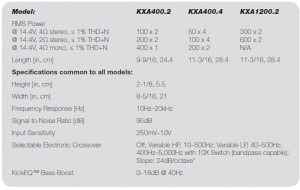
 KXA400.2100 x 2 @ 4 ohms, 14.4VDC, 1% THD, CEA-2006B (Watts)Signal to Noise Ratio -75dB CEA-2006B (ref: 1W, A-weighted)
KXA1200.2300 x 2 @ 4 ohm, 14.4VDC, 1% THD, CEA-2006B (Watts)Signal to Noise Ratio -75dB CEA-2006B (ref: 1W, A-weighted)
KXA400.450 x 4 @ 4 ohms, 14.4VDC, 1% THD, CEA-2006B (Watts)Signal to Noise Ratio -75dB CEA-2006B (ref: 1W, A-weighted)
Read More About This Manual & Download PDF:
KICKER KXA400.2/ KXA1200.2/ KXA400.4 Amplifiers Owner’s Manual – KICKER KXA400.2/ KXA1200.2/ KXA400.4 Amplifiers Owner’s Manual –
[xyz-ips snippet=”download-snippet”]