

The Klip Motor DriverUser Guide
Introduction
Welcome to the Kitronik Klip Motor User Guide for the BBC micro: bit.This guide aims to provide all the essential information and instructions required to get started using, and teaching others about, the Klip Motor board. There is an overview of its various functions and features; a description of how to use it and what other Kitronik products will work well with it; an explanation of how to program the BBC micro: bit to control the Klip Motor, with a particular focus on the Kitronik Klip Motor Extension for Microsoft MakeCode; some starter examples of projects which could be carried out with the board; and finally a more in-depth description of how the motor driver works.For any further queries or support, please visit the Kitronik website: www.kitronik.co.uk/5655Or get in touch via Telephone: +44 (0) 845 8380781Sales email: [email protected]Tech support email: [email protected]
What it does
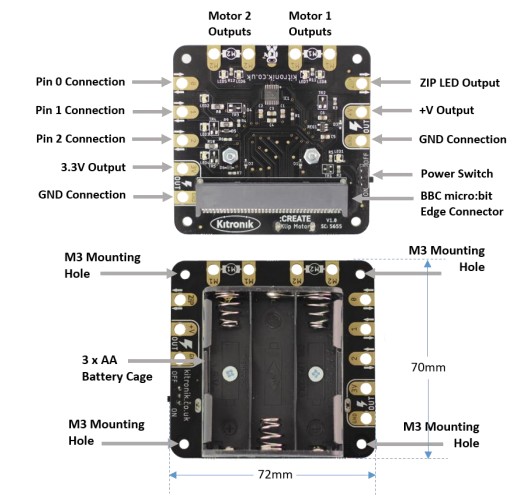
The Klip Motor is an accessory board for the BBC micro: bit, expanding and augmenting its functionality. It has been designed to be completely soldered and a jumper wire-free, instead of enabling the use of crocodile clips or banana plugs on all of its input, output, and power connections. It also includes an integrated 3 x AA battery ack, avoiding the need for extra trailing wires, and an easily accessible on/off switch.
It is capable of independently driving two DC motors clockwise and counter-clockwise at variable speeds. Indicator LEDs (red and green) on the motor connections indicate when these outputs are in use, and which direction they are turning.
There are also breakout pads for BBC micro: bit pins 0, 1, and 2, which can all be used as inputs and outputs, and 3V and GND outputs, just like the main pads on the BBC micro: bit itself. The 0, 1, and 2 pads all have green indicator LEDs to quickly identify when they are in use. There is a ZIP LED data output pad as well, which – along with the battery voltage and extra GND breakout pads – means bright, full color lighting an be added to projects quickly and easily.
A BBC micro: bit is used with the Klip Motor board can be easily attached and removed due to the use of a plug-in connector. When in place, the micro: bit LED display is clearly visible and the buttons are free to use.
Safety and usability have been a key part of the design process of his product. All four corners of the board are rounded; the battery holder has reverse polarity protection to void problems if the batteries are inserted incorrectly; there is overcurrent, overvoltage and short circuit protection on the breakout pads in case of accidental connecting of the wrong wires; the pads are well spaced to minimize the chance of short circuits; and essential circuitry is well out of reach of any crocodile clips, with the attery cage acting as a barrier.
Useful Accessories
The Klip Motor board is compatible with a number of Kitronik products already available, including motors, BBC micro: bit accessories, and LEDs.
The main accessory used across all projects involving the Klip Motor will be crocodile clips; having a variety of colors and lengths will be helpful (https://www.kitronik.co.uk/2407).There are some motors with add-on boards to make them ready for crocodile clip connections:
- Solderless TT Motor (https://www.kitronik.co.uk/2594)Kitronik Wheels for TT motor https://www.kitronik.co.uk/2593-TT
- Solderless Gear Motor (https://www.kitronik.co.uk/2591-solderless-gear-motor.html)Kitronik Wheels for Solderless Gear motor https://www.kitronik.co.uk/2593-D
For adding ZIP LEDs to Klip Motor projects, the ZIP Hex (https://www.kitronik.co.uk/35140-zip-hex- led-pack-of-5.html) boards are perfect as they specifically designed for crocodile clips, and have all the connections necessary for linking multiple LEDs together in a continuous chain.All of the Kitronik: CITY products can be used, as they only ever use the main BBC micro: bit pins:
- STOP:bit (https://www.kitronik.co.uk/5642-stopbit-traffic-light-for-bbc-microbit.html)
- LAMP:bit (https://www.kitronik.co.uk/5643-lampbit-street-light-for-bbc-microbit.html)
- ACCESS:bit (https://www.kitronik.co.uk/5646-accessbit-for-bbc-microbit.html)
Many of the Electro-Fashion range have connections suitable for using with crocodile clips, for instance:
- https://www.kitronik.co.uk/e-textiles-conductive-thread/switches-and-sensors.html
- https://www.kitronik.co.uk/e-textiles-conductive-thread/e-textiles-buzzers.html
- https://www.kitronik.co.uk/e-textiles-conductive-thread/leds-for-e-textiles.html
As well as connecting other circuit boards to the Klip Motor, basic components like LEDs, switches, buzzers, and simple sensors can also be connected, providing plenty of options and opportunities for education and creativity.

How to code it
The Klip Motor board is designed to be controlled by programs on the BBC micro: bit, which can be created in the Microsoft MakeCode, MicroPython, or other BBC micro: bit compatible environments. This guide focuses on Microsoft MakeCode.
Although many standard MakeCode blocks can be used with the Klip Motor, Kitronik has also created a custom extension to accompany the board, which makes the control of motors and ZIP LEDs much easier.
To begin, go to https://makecode.microbit.org/.
Start a new project:

Once the new project has opened, the Klip Motor Extension can be added (along with any others that are required). First click on the ‘Advanced’ arrow:

Then scroll to the bottom and click ‘Extensions’:

This will bring up the search bar. Search for ‘Kitronik’. This will display all the extensions available from Kitronik. Select the ‘kitronik-Klip-motor’:
This will add an extension to the current project. Once the process is complete, there should be a new item in the blocks list:

Clicking on this will reveal all the blocks available in the extension:
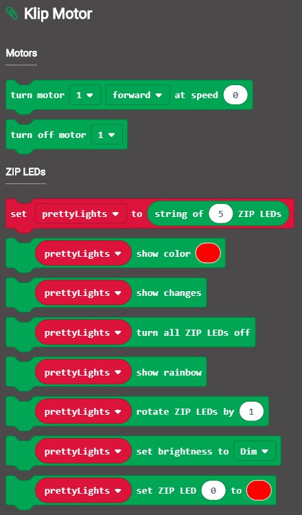
Within the extension, the blocks are split by motor control and ZIP LED control. A short description of the function of each block is given in the table below:
DescriptionThis block starts a specific motor (either 1 or 2) spinning in a set direction (forward or reverse) at a set speed (0 to 100%).Block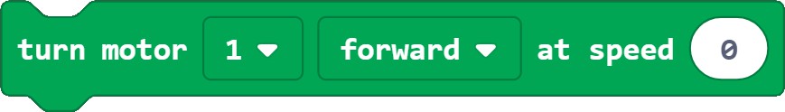
This block stops a specific motor from spinning (either 1 or 2).

This block sets up the ZIP LEDs attached to the Klip Motor board as a variable, enabling them to be controlled in the program. The number of ZIP LEDs can be changed to match the number connected. BBCmicro: bit pin connection is automatically assigned to the ZIP pad.

This block sets all the ZIP LEDs to be the color selected in the color picker and then makes those changes visible.


This block makes changes visible on the ZIP LEDs, such as setting individual ZIP LED colors or rotating the LEDs.

This block turns off all the ZIP LEDs attached to the Klip Motor board.

This block sets a rainbow pattern to be displayed across all the ZIP LEDs attached to the Klip Motor board. It can be used in conjunction with the rotate and show changes blocks to make the rainbow pattern move all the ZIP LEDs.

This block moves all the color settings for the ZIP LEDs along with a certain number of ZIP LEDs in the string the default is 1). The rotate block views the string of ZIP LEDs as a continuous loop, so the settings of the last IP LED will move to the first ZIP LED.

This block sets the brightness of the ZIP LEDs to one of the four brightness options. These approximate to the following percentages: Dim = 10%, Normal = 50%, Bright = 80%, Super Bright = 100%. (Note: The rightness will only change for events occurring after this block is used).


This block sets a particular ZIP LED to be the color selected in the color picker. However, this will not be ade visible until the show changes block is called. (Note: The first ZIP LED in the string connected to the Klip Motor board will be ‘ZIP LED 0’, and the numbers count up from there).

Example Program
An example program using all the blocks in the Klip Motor Extension can be seen by following the link below: https://makecode.microbit.org/_LRfcowLAieroThe program starts by setting up three ZIP LEDs to be attached to the Klip Motor board, with their brightness set to ‘Normal’. The first ZIP LED in the chain, LED 0, is set to be red and then the changes are made visible. Nothing else will happen until either button A or B on the BBC micro: bit is pressed.If button A is pressed, a rainbow pattern will be displayed across the ZIP LEDs attached to the board. The color pattern will then rotate around the ZIP LED chain 25 times before all the ZIP LEDs are turned off.
If button B is pressed, all the ZIP LEDs will light up green. After that, both motors will turn in the forward direction at 75% speed for two seconds before turning off. There will then be a 500 ms pause before they both turn on again, this time spinning in the opposite direction and now at 50% speed. They will spin for two seconds before once again both turning off.
Other ExtensionsAs well as using the specific Klip Motor Extension, there are also other Extensions available that work well with the Klip Motor and can be used at the same time as the Klip Motor Extension. Three of these are other Kitronik Extensions that go alongside the Kitronik: CITY products talked about in the ‘How to use it’ section of this guide: 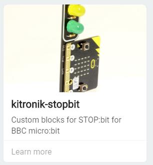

 The Klip Motor board is also compatible with the ‘Neopixel’ extension (Note: the ZIP LED output on the Klip Motor is linked to Pin 8 on the BBC micro: bit).
Example Projects
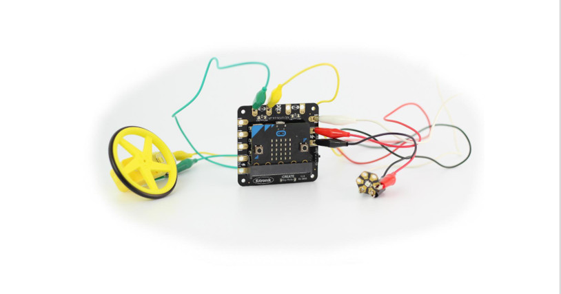
Some example project setups are outlined in this guide to provide a starting point for using the Klip Motor. Writing programs to control the Klip Motor is dealt with in the ‘How to code it’ section.Example 1 – Driving two motorsEquipment required:
- 1 x Klip Motor board (https://kitronik.co.uk/5655)
- 1 x BBC micro:bit (https://www.kitronik.co.uk/5613)
- 2 x crocodile clip compatible motors (https://www.kitronik.co.uk/2594)
- 4 x crocodile clip leads (https://www.kitronik.co.uk/2407)
- 3 x AA batteries
Wiring Diagram:

Connect crocodile clip leads between the motor outputs on the Klip Motor board (one pair labeled M1 and the other labeled M2), and the exposed pads on the solderless motor attachment boards.
Program a BBC micro: bit (explained in the ‘How to code it’ section of this guide) and slot this into the edge connector on the Klip Motor board with the LED display facing up (as shown in the wiring diagram above).
A short test program can be found using the link below: https://makecode.microbit.org/_3t7c9d6gEJ6h
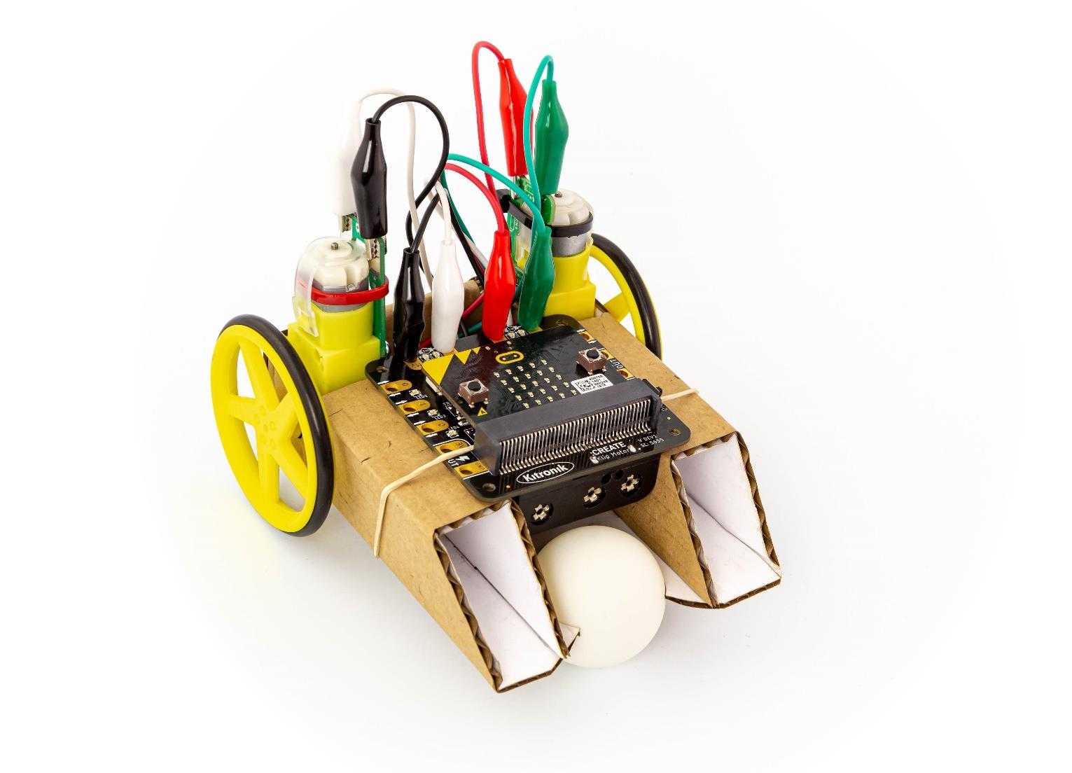
Pressing button A on the micro: bit will start the motors at half speed, pressing button b will stop This project is an ideal starting point as the connections and programming are simple; plus, it leaves room for lots of creativity as there are now the beginnings of a two-wheeled robot…
Example 2 – ZIP Hex Boards
Equipment required:
- 1 x Klip Motor board (https://kitronik.co.uk/5655)
- 1 x BBC micro:bit (https://www.kitronik.co.uk/5613)
- 3 x ZIP Hex boards (https://www.kitronik.co.uk/35140)
- 9 x crocodile clip leads (https://www.kitronik.co.uk/2407)
- 3 x AA batteries
Wiring Diagram:
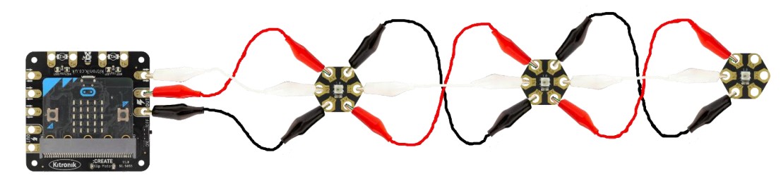
Connect crocodile clip leads between the +V connections on the Klip Motor board and the first ZIP Hex board, then continue connecting along to the +V connections on the next two ZIP Hex boards. Next, connect crocodile clip leads between the GND connections on the Klip Motor board and first ZIP Hex board, then continue connecting along to the GND connections on the next two ZIP Hex boards. Finally, connect crocodile clip leads between the ZIP output on the Klip Motor board and the IN connection on the first ZIP Hex board, then continue connecting the OUTs to INs on the next two ZIP Hex boards.
Program a BBC micro: bit (explained in the ‘How to code it’ section of this guide) and slot this into the edge connector on the Klip Motor board with the LED display facing up (as shown in the wiring diagram above).
A short test program can be found using the link below: https://makecode.microbit.org/_Kii63F9VY6yt
Pressing button A on the micro: bit will turn the lights green, pressing button B will turn them blue, and pressing both A and B together will turn them off.
(Note: The example program given in the ‘How to code it’ section of this guide controls a combination of examples 1 and 2)
Example 3 – STOP: bit
Equipment required:
- 1 x Klip Motor board (https://kitronik.co.uk/5655)
- 1 x BBC micro:bit (https://www.kitronik.co.uk/5613)
- 1 x STOP:bit (https://www.kitronik.co.uk/5642)
- 4 x crocodile clip leads (https://www.kitronik.co.uk/2407)
- 3 x AA batteries Wiring Diagram:
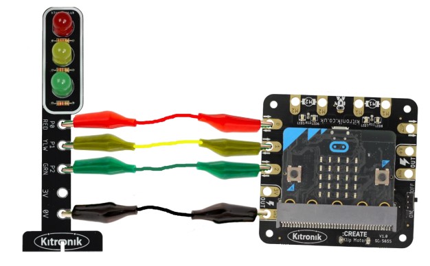
Connect crocodile clip leads between the Pin 0 output on the Klip Motor board and P0 on the STOP: bit, the Pin 1 output on the Klip Motor board and P1 on the STOP: bit, the Pin 2 output on the Klip Motor board, and P2 on the STOP: bit, and finally the GND connection on the Klip Motor board and the GND connection on the STOP: bit.
Program a BBC micro: bit (explained in the ‘How to code it’ section of this guide) and slot this into the edge connector on the Klip Motor board with the LED display facing up (as shown in the wiring diagram above).
A short test program can be found using the link below: https://makecode.microbit.org/_h1HFd0d3X5cX
This program runs a UK traffic light sequence continually.Note: The ‘kitronik-stop bit MakeCode Extension is required for this project.
Example 4 – LAMP: bit
Equipment required:
- 1 x Klip Motor board (https://kitronik.co.uk/5655)
- 1 x BBC micro:bit (https://www.kitronik.co.uk/5613)
- 1 x LAMP:bit (https://www.kitronik.co.uk/5643)
- 4 x crocodile clip leads (https://www.kitronik.co.uk/2407
- 3 x AA batteries
Wiring Diagram:
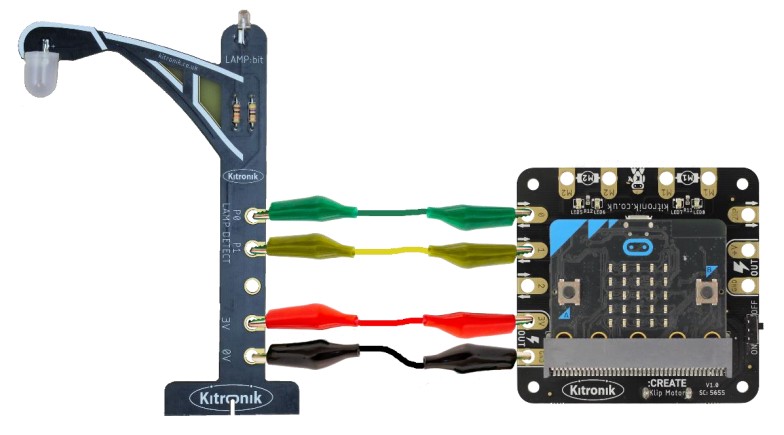
Connect crocodile clip leads between the Pin 0 output on the Klip Motor board and P0 on the LAMP: bit, the Pin 1 output on the Klip Motor board and P1 on the LAMP: bit, the 3V output on the Klip Motor board, and the 3V connection on the LAMP: bit, and finally the GND connection on the Klip Motor board and the GND connection on the LAMP: bit.
Program a BBC micro: bit (explained in the ‘How to code it’ section of this guide) and slot this into the edge connector on the Klip Motor board with the LED display facing up (as shown in the wiring diagram above).
A short test program can be found using the link below: https://makecode.microbit.org/_701fukedafPA
This program turns on the Lamp when it becomes dark.Note: The ‘kitronik-lampbit’ MakeCode Extension is required for this project.
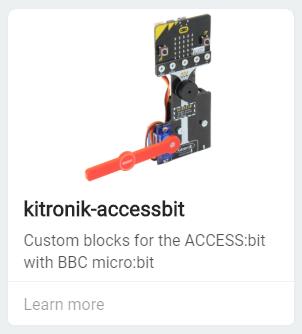
Example 5 – ACCESS: bit
Equipment required:
- 1 x Klip Motor board (https://kitronik.co.uk/5655)
- 1 x BBC micro:bit (https://www.kitronik.co.uk/5613)
- 1 x ACCESS:bit (https://www.kitronik.co.uk/5643)
- 3 x crocodile clip leads (https://www.kitronik.co.uk/2407)
- 3 x AA batteries
- 3 x AAA batteries Wiring Diagram:
Wiring Diagram:
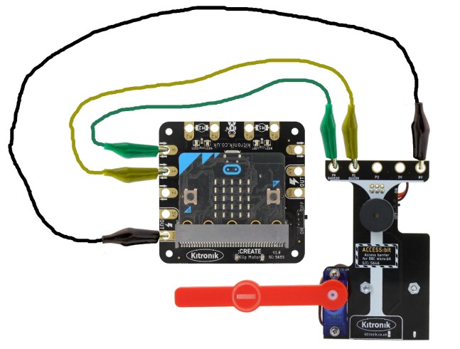
Connect crocodile clip leads between the Pin 0 output on the Klip Motor board and P0 on the ACCESS: bit, the Pin 1 output on the Klip Motor board and P1 on the ACCESS: bit, the 3V output on the Klip Motor board, and the 3V connection on the ACCESS: bit, and finally the GND connection on the Klip Motor board and the GND connection on the ACCESS: bit.
The ACCESS: bit requires its own battery supply in order for the servo to be driven (3 x AAA).
Program a BBC micro: bit (explained in the ‘How to code it’ section of this guide) and slot this into the edge connector on the Klip Motor board with the LED display facing up (as shown in the wiring diagram above).
A short test program can be found using the link below: https://makecode.microbit.org/_YrgdwJimahJe
This program moves the barrier up and beeps twice when button A on the micro: bit is pressed, and moves it down, with a single beep when button B is pressed.
Note: The ‘kitronik-accessbit’ MakeCode Extension is required for this project.
How it works – The Motor Driver
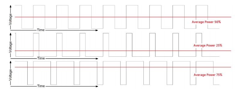
Each motor is operated using two BBC micro: bit IO pins to provide control signals to a motor driver IC; pins 15 and 16 for Motor 1 and pins 13 and 14 for Motor 2. The signals from the BBC micro: bit use a technique called Pulse Width Modulation (PWM) to control the voltage seen across the motors, which then controls their speed. The PWM signals are square waves that have the ‘ON’ and ‘OFF’ times set to a particular ratio, known as the duty cycle. If the ‘ON’ and ‘OFF’ times are equal, then the duty cycle is 50%, if the ‘ON’ time is greater, then the duty cycle is greater than 50%, and if the ‘OFF’ time is greater, then the duty cycle is less than 50%. As the PWM signals are controlling the voltage seen at the motor outputs, the average power being provided to the motors is equal to the duty cycle. The higher the duty cycle, the greater the motor speed. This is illustrated in the diagram below:
However, the PWM signals from the BBC micro: bit does not go directly to the motors as the current draw requirements for the motors would be far too high for the BBC micro: bit to provide. Instead, the signals control a motor driver IC which contains an ‘H-bridge’ circuit for each motor (so-called due to the schematic looking like a capital ‘H’). They have four Field Effect Transistors (FETs), operating as switches, which are controlled in pairs – in this case, a pair of FETs for each of pins 13, 14, 15, and 16. The diagram below provides an example scenario for the Klip Motor board. Ford Motor 1, pin 15 drives a PWM control signal, which switches on its associated FETs; pin 16 is held at 0V, which switches off its associated FETs. This enables the current flow through the motor, as shown by the red arrows, turning the motor forwards. Ford Motor 2, the PWM signal is on pin 14, and pin 13 is held at 0V. The current flow is the opposite of Motor 1, turning the motor in reverse. Driving the pins 16 and 14 with a PWM control signal would cause the motors to turn in the opposite direction.

References
Kitronik Yellow Wheels – Kitronik Ltd Kitronik American Express Apple Pay Diners Club Discover Google Pay Maestro Mastercard PayPal Shop Pay Visa American Express Apple Pay Diners Club Discover Google Pay Maestro Mastercard PayPal Shop Pay Visa
Microsoft MakeCode for micro:bit
Kitronik Klip Motor Driver for BBC micro:bit – Kitronik Ltd Kitronik American Express Apple Pay Diners Club Discover Google Pay Maestro Mastercard PayPal Shop Pay Visa American Express Apple Pay Diners Club Discover Google Pay Maestro Mastercard PayPal Sho
Kitronik Klip Motor – LAMPbit
Kitronik Klip Motor – STOPbit
Kitronik Klip Motor Driver for BBC micro:bit – Kitronik Ltd Kitronik American Express Apple Pay Diners Club Discover Google Pay Maestro Mastercard PayPal Shop Pay Visa American Express Apple Pay Diners Club Discover Google Pay Maestro Mastercard PayPal Sho
Kitronik LAMP:bit – Street Light for BBC micro:bit – Kitronik Ltd Kitronik American Express Apple Pay Diners Club Discover Google Pay Maestro Mastercard PayPal Shop Pay Visa American Express Apple Pay Diners Club Discover Google Pay Maestro Mastercard PayP
LEDs for E-Textiles – Kitronik Ltd Kitronik American Express Apple Pay Diners Club Discover Google Pay Maestro Mastercard PayPal Shop Pay Visa
Kitronik LAMP:bit – Street Light for BBC micro:bit – Kitronik Ltd Kitronik American Express Apple Pay Diners Club Discover Google Pay Maestro Mastercard PayPal Shop Pay Visa American Express Apple Pay Diners Club Discover Google Pay Maestro Mastercard PayP
E-Textiles Switches & Sensors – Kitronik Ltd Kitronik American Express Apple Pay Diners Club Discover Google Pay Maestro Mastercard PayPal Shop Pay Visa
📧[email protected]
kitronik.co.uk/35140-zip-hex-led-pack-of-5.html
Kitronik Klip Motor – 3 ZIP Hex
Kitronik STOP:bit – Traffic Light for BBC micro:bit – Kitronik Ltd Kitronik American Express Apple Pay Diners Club Discover Google Pay Maestro Mastercard PayPal Shop Pay Visa American Express Apple Pay Diners Club Discover Google Pay Maestro Mastercard Pay
Kitronik ACCESS:bit for BBC micro:bit – Kitronik Ltd Kitronik American Express Apple Pay Diners Club Discover Google Pay Maestro Mastercard PayPal Shop Pay Visa American Express Apple Pay Diners Club Discover Google Pay Maestro Mastercard PayPal Shop Pay V
BBC micro:bit (Board Only) – Kitronik Ltd Kitronik American Express Apple Pay Diners Club Discover Google Pay Maestro Mastercard PayPal Shop Pay Visa American Express Apple Pay Diners Club Discover Google Pay Maestro Mastercard PayPal Shop Pay Visa
📧[email protected]
Crocodile Leads, pack of 10 – Kitronik Ltd Kitronik American Express Apple Pay Diners Club Discover Google Pay Maestro Mastercard PayPal Shop Pay Visa American Express Apple Pay Diners Club Discover Google Pay Maestro Mastercard PayPal Shop Pay Visa
Kitronik Klip Motor – ACCESSbit
Kitronik Green Wheels – Kitronik Ltd Kitronik American Express Apple Pay Diners Club Discover Google Pay Maestro Mastercard PayPal Shop Pay Visa American Express Apple Pay Diners Club Discover Google Pay Maestro Mastercard PayPal Shop Pay Visa
E-Textiles Kits – Kitronik Ltd Kitronik American Express Apple Pay Diners Club Discover Google Pay Maestro Mastercard PayPal Shop Pay Visa
Kitronik Klip Motor – Motors & Lights
Kitronik STOP:bit – Traffic Light for BBC micro:bit – Kitronik Ltd Kitronik American Express Apple Pay Diners Club Discover Google Pay Maestro Mastercard PayPal Shop Pay Visa American Express Apple Pay Diners Club Discover Google Pay Maestro Mastercard Pay
Kitronik ZIP Hex LED, pack of 5 – Kitronik Ltd Kitronik American Express Apple Pay Diners Club Discover Google Pay Maestro Mastercard PayPal Shop Pay Visa American Express Apple Pay Diners Club Discover Google Pay Maestro Mastercard PayPal Shop Pay Visa
Solderless Gear Motor – Kitronik Ltd Kitronik American Express Apple Pay Diners Club Discover Google Pay Maestro Mastercard PayPal Shop Pay Visa American Express Apple Pay Diners Club Discover Google Pay Maestro Mastercard PayPal Shop Pay Visa
Kitronik Solderless TT Motor Adapter Board – Kitronik Ltd Kitronik American Express Apple Pay Diners Club Discover Google Pay Maestro Mastercard PayPal Shop Pay Visa American Express Apple Pay Diners Club Discover Google Pay Maestro Mastercard PayPal Shop
Kitronik Klip Motor – 2 Motors
[xyz-ips snippet=”download-snippet”]