
KLARK TEKNIK 2.4 GHz Wireless Stereo Receiver Transmitter High-Performance Stereo Audio Broadcasting User Manual
Product Overview
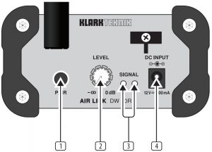
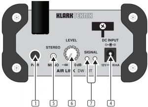
- PAIR button enables the unit to become available for pairing by pressing and holding for 4 seconds. The LED ring will indicate the current status.See the Getting Started section for details.
- LEVEL knob adjusts the volume of the signal sent to the output jacks.
- SIGNAL LEDs light when the DW 20R receives an audio signal from the DW 20T.
- DC INPUT socket accepts the included power adapter.
- STEREO/MONO switch determines whether the outgoing wireless audio signal is stereo or mono.
- LEVEL knob adjusts the sensitivity of the inputs.
- SIGNAL LEDs light green when signal is present at the inputs. The LEDs light red when the incoming audio signal clips the inputs.If this happens, lower the output level of the source audio.
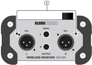
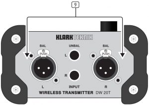
- OUTPUT jacks send a line-level audio signal to another audio device (mixer, amplifier, etc.) via balanced XLR or unbalanced ¼” TS cables.
- INPUT jacks accept audio signals via balanced XLR or unbalanced ¼” TS cables.
Getting Started
- Connect the DW 20T inputs to an original audio source such as a mixer or media player, then connect the outputs of the DW 20R to a destination such as a mixer, amplifier, or active speaker. Leave the amp or speakers turned off for now.
- Connect the power adapters to each unit. They will power on automatically and their PAIR buttons will blink slowly to indicate standby mode.
- Press and hold the PAIR button on the DW 20T for 4 seconds. The LED ring will fl ash rapidly to indicate that it is trying to pair, and will continue trying for up to 30 seconds.
- Within 30 seconds of initiating the DW 20T for pairing, press and hold the PAIR button on the DW 20R for 4 seconds as well. Its LED ring will fl ash rapidly.
- When successfully paired, the LED rings on both the 20T and 20R will light solid (not fl ashing). If either unit’s LED ring fl ashes slowly, this indicates that pairing was unsuccessful. Make sure both units are free of obstructions and are within 100 feet / 30 meters of each other.
- After all audio and power connections have been made, power on the amplifier or active speakers.
Pairing multiple DW 20R units with a DW 20T
- Connect the DW 20T and the fi rst DW 20R as described in ‘Getting Started’ (hold each PAIR button for 4 seconds).
- On the second DW 20R unit, hold the PAIR button for 4 seconds to activate pairing, then let it search for 30 seconds. The pairing function will time out after 30 seconds and the LED will blink slowly.
- Press the DW 20T PAIR button for 4 seconds, and then press the second DW 20R unit’s PAIR button for 4 seconds. Both DW 20R units will now be connected to the same DW 20T.
- Note – holding the PAIR button for 10 seconds on the DW 20T will clear the memory of connected DW 20R units.
Specifications
|
DW 20R |
DW 20T |
|
| Inputs
|
||
| Connectors |
— |
Balanced XLR, unbalanced ¼” |
| Impedance |
— |
10 kΩ balanced, 15 kΩ unbalanced |
| Max. input level |
— |
10 dBu |
| Outputs | ||
| Connectors | Balanced XLR, unbalanced ¼” |
— |
| Impedance | 240 Ω balanced,
120 Ω unbalanced |
— |
| Max. output level | 15 dBu |
— |
| Wireless | ||
| Channels | 24 | |
| Transmission frequency | 2.406 – 2.475 GHz | |
| Wireless range | Up to 30 m (100 ft) | |
| Sensitivity | -81 dBm @ 1% PER |
— |
| Transmission power |
— |
12 dBm |
| System | |
| Frequency response | 20 Hz to 20 kHz (±1 dB) |
| THD + N (distortion) | 0.1% @ 1 kHz |
| Signal-to-noise ratio | >90 dB |
| Power adaptor | 12 V DC, 400 mA, center positive |
| Physical | |
| Dimensions (H x W x D) | |
| Without bumpers or antenna | 54 x 108 x 103 mm (2.1 x 4.3 x 4.1″) |
| With bumpers, without antenna | 63 x 118 x 112 mm (2.5 x 4.6 x 4.4″) |
| With bumpers, upright antenna | 212 x 118 x 126 mm (8.3 x 4.6 x 5.0″) |
| Weight (incl. bumpers and antenna) | 0.6 kg (1.3 lbs) |
Antenna Information
The DW 20T has been designed to pass certification with the antennas listed below, specified as a dipole Yagi antenna, 50 Ω impedance and maximum gain of 5.0 dBi. End users should not change the antenna to a different type.
Table for Filed Antenna:
Group 1
|
Ant. |
Brand | Model Name | Antenna Type | Connector |
Gain (dBi) |
|
1 |
Zhigaoda | 323032-25532-1R | Dipole | N/A |
5 |
Group 2
|
Ant. |
Mic Brand | Model Name | Antenna Type | Connector |
Gain (dBi) |
|
1 |
AT-02-5 -A80617H1-190 | Dipole | N/A |
5 |
Note:1 Equipment has 2 group antennas, group 1 and group 2 are same type antenna, only dierin brand model name. Only transmitter and Receiver spurious emissions recorded the test result for two group antennas.
LEGAL DISCLAIMER
MUSIC Tribe accepts no liability for any loss which may be suffered by any person who relies either wholly or in part upon any description, photograph, or statement contained herein. Technical specifi cations, appearances and other information are subject to change without notice. All trademarks are the property of their respective owners. MIDAS, KLARK TEKNIK, LAB GRUPPEN, LAKE, TANNOY, TURBOSOUND, TC ELECTRONIC, TC HELICON, BEHRINGER, BUGERA and COOLAUDIO are trademarks or registered trademarks of MUSIC Tribe Global Brands Ltd. © MUSIC Tribe Global Brands Ltd. 2018 All rights reserved.
LIMITED WARRANTY
For the applicable warranty terms and conditions and additional information regarding MUSIC Tribe’s Limited Warranty, please see complete details online at musictri.be/warranty.
FEDERAL COMMUNICATIONS COMMISSION COMPLIANCE INFORMATION
![]() KLARK TEKNIKAIR LINK DW 20R/DW 20T
KLARK TEKNIKAIR LINK DW 20R/DW 20T
Responsible Party Name: MUSIC Tribe Commercial NV Inc.Address: 5270 Procyon Street Las Vegas, NV 89118 USAPhone Number: +1 702 800 8290
AIR LINK DW 20R/DW 20T
complies with the FCC rules as mentioned in the following paragraph:
This equipment has been tested and found to comply with the limits for a Class B digital device, pursuant to part 15 of the FCC Rules. These limits are designed to provide reasonable protection against harmful interference in a residential installation.
This equipment generates, uses and can radiate radio frequency energy and, if not installed and used in accordance with the instructions, may cause harmful interference to radio communications. However, there is no guarantee that interference will not occur in a particular installation. If this equipment does cause harmful interference to radio or television reception, which can be determined by turning the equipment off and on, the user is encouraged to try to correct the interference by one or more of the following measures:
- Reorient or relocate the receiving antenna.
- Increase the separation between the equipment and receiver.
- Connect the equipment into an outlet on a circuit different from that to which the receiver is connected.
- Consult the dealer or an experienced radio/TV technician for help.
This equipment complies with Part 15 of the FCC Rules. Operation is subject to the following two conditions:
- This device may not cause harmful interference, and
- This device must accept any interference received, including interference that may cause undesired operation.
FCC ID: QWHDW20TThis transmitter must not be co-located or operating in conjunction with any other antenna or transmitter.
Caution!
The MUSIC Tribe is not responsible for any radio or TV interference caused by unauthorized modifications to this equipment. Such modifications could void the user authority to operate the equipment
FCC RF Radiation Exposure Statement:
- This Transmitter must not be co-located or operating in conjunction with any other antenna or transmitter.
- This equipment complies with FCC RF radiation exposure limits set forth for an uncontrolled environment. This equipment should be installed and operated with a minimum distance of 20 centimeters between the radiator and your body.
References
[xyz-ips snippet=”download-snippet”]