![]()
Quick Start Guide
![]() 2A-KTClassic Leveling Amplifier with Vacuum Tubes, Optical Attenuator and Midas Transformers
2A-KTClassic Leveling Amplifier with Vacuum Tubes, Optical Attenuator and Midas Transformers
Important Safety Instructions
 Terminals marked with this symbol carry an electrical current of sufficient magnitude to constitute a risk of electric shock.Use only high-quality professional speaker cables with ¼” TS or twist-locking plugs pre-installed. All other installation or modifications should be performed only by qualified personnel.
This symbol, wherever it appears, alerts you to the presence of uninsulated dangerous voltage inside the enclosure – voltage that may be sufficient to constitute a risk of shock.
 This symbol, wherever it appears, alerts you to important operating and maintenance instructions in the accompanying literature. Please read the manual. CautionTo reduce the risk of electric shock, do not remove the top cover (or the rear section).No user-serviceable parts inside. Refer servicing to qualified personnel. CautionTo reduce the risk of fire or electric shock, do not expose this appliance to rain and moisture. The apparatus shall not be exposed to dripping or splashing liquids and no objects filled with liquids, such as vases, shall be placed on the apparatus. CautionThese service instructions are for use by qualified service personnel only.To reduce the risk of electric shock do not perform any servicing other than that contained in the operation instructions. Repairs have to be performed by qualified service personnel.
- Read these instructions.
- Keep these instructions.
- Heed all warnings.
- Follow all instructions.
- Do not use this apparatus near water.
- Clean only with a dry cloth.
- Do not block any ventilation openings. Install in accordance with the manufacturer’s instructions.
- Do not install near any heat sources such as radiators, heat registers, stoves, or other apparatus (including amplifiers) that produce heat.
- Do not defeat the safety purpose of the polarized or grounding-type plug. A polarized plug has two blades with one wider than the other. A grounding-type plug has two blades and a third grounding prong. The wide blade or the third prong are provided for your safety. If the provided plug does not fit into your outlet, consult an electrician for the replacement of the obsolete outlet.
- Protect the power cord from being walked on or pinched particularly at plugs, convenience receptacles, and the point where they exit from the apparatus.
- Use only attachments/accessories specified by the manufacturer.
 Use only with the cart, stand, tripod, bracket, or table specified by the manufacturer, or sold with the apparatus. When a cart is used, use caution when moving the cart/apparatus combination to avoid injury from tip-over.
- Unplug this apparatus during lightning storms or when unused for long periods of time.
- Refer all servicing to qualified service personnel.Servicing is required when the apparatus has been damaged in any way, such as power supply cord or plug is damaged, liquid has been spilled or objects have fallen into the apparatus, the apparatus has been exposed to rain or moisture, does not operate normally, or has been dropped.
- The apparatus shall be connected to a MAINS socket outlet with a protective earthing connection.
- Where the MAINS plug or an appliance coupler is used as the disconnect device, the disconnect device shall remain readily operable.
- Correct disposal of this product: This symbol indicates that this product must not be disposed of with household waste, according to the WEEE Directive (2012/19/EU) and your national law. This product should be taken to a collection center licensed for the recycling of waste electrical and electronic equipment (EEE). The mishandling of this type of waste could have a possible negative impact on the environment and human health due to potentially hazardous substances that are generally associated with EEE. At the same time, your cooperation in the correct disposal of this product will contribute to the efficient use of natural resources.For more information about where you can take your waste equipment for recycling, please contact your local city office or your household waste collection service.
- Do not install in a confined space, such as a bookcase or similar unit.
- Do not place naked flame sources, such as lighted candles, on the apparatus.
 Use only with the cart, stand, tripod, bracket, or table specified by the manufacturer, or sold with the apparatus. When a cart is used, use caution when moving the cart/apparatus combination to avoid injury from tip-over.
 Correct disposal of this product: This symbol indicates that this product must not be disposed of with household waste, according to the WEEE Directive (2012/19/EU) and your national law. This product should be taken to a collection center licensed for the recycling of waste electrical and electronic equipment (EEE). The mishandling of this type of waste could have a possible negative impact on the environment and human health due to potentially hazardous substances that are generally associated with EEE. At the same time, your cooperation in the correct disposal of this product will contribute to the efficient use of natural resources.For more information about where you can take your waste equipment for recycling, please contact your local city office or your household waste collection service.
2A-KT Controls
Controls
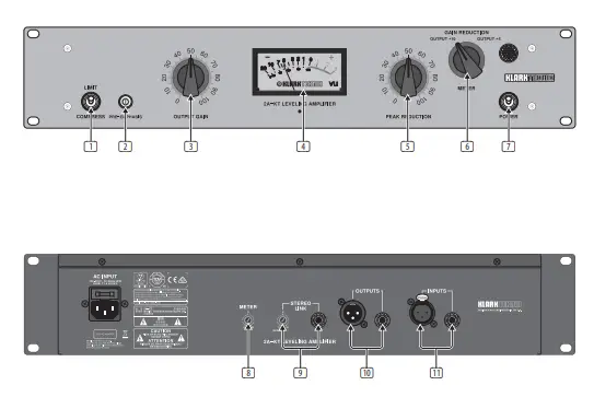
- LIMIT/COMPRESS switch affects the compression ratio, going from a fixed compression ratio in Compress mode, and shifting to a near-infinite ratio in Limit mode.
- PRE-EMPHASIS trimmer adjusts the sidechain that the compressor responds to but does not affect the audio directly in any way. Set fully clockwise to the ‘Default’ position, the sidechain responds to the full frequency bandwidth of the incoming audio.As the trimmer is turned counterclockwise, the compressor responds less to high-frequency transients.
- OUTPUT GAIN knob sets the overall level sent from the unit.
- VU METER displays either the amount of gain reduction or the output level, depending on which operation is selected.
- PEAK REDUCTION knob controls the threshold of the compressor/limiter. A maximum of 40 dB gain reduction is available, which is likely more than any practical scenario would require unless used in a parallel compression setup.
- METER SELECT knob determines whether the VU Meter displays the amount of gain reduction or the output level. When set to output level mode, a meter reading of 0 dB corresponds to an output level of +4 or +10 dBu, depending on the selection.
- The POWER switch turns the unit on and off.The LED will light to indicate the unit is powered on.
- METER CALIBRATION knob allows the meter to be adjusted for accuracy by following these steps:• Disconnect any audio cables from the rear panel, then turn the unit on• Select ‘Reduction’ on the Meter Select knob• Adjust the calibration knob until the meter reads 0 dB
- STEREO LINK allows a pair of 2A-KT units to be connected via standard ¼” TRS cable, sharing the threshold response between them by blending the sidechain signals. The front panel controls should still beset the same between the 2 units, and the output levels should be carefully balanced. To calibrate the stereo balance, follow these steps:• Connect the units with a short ¼” TRS shielded cable• Turn the Peak Reduction knob fully counterclockwise• Set both Meter Select knobs to show gain reduction• Turn both Stereo Link trimmers to the Default setting• Play a mono test signal into both units simultaneously, and turn the Peak Reduction knobs up on both units until gain reduction registers on the meter.Set the Peak Reduction knobs identically, and the meters should show a very similar response to one another.• If one unit shows more reduction than the other, turn that unit’s Stereo Link trimmer clockwise until the meters match.
- OUTPUTS are available as balanced ¼” and XLR connectors.
- INPUTS are available as balanced ¼” and locking XLR connectors.
Specifications
| Audio Input | |
| Type | XLR, ¼” TRS, transformer balanced |
| Impedance | 600 Ω, balanced and unbalanced |
| Maximum input level | +20 dBu, balanced and unbalanced |
| CMRR at 1 kHz | Typically -80 dB |
| Audio Output | |
| Type | XLR, ¼” TRS, transformer balanced |
| Impedance | 70 Ω, balanced and unbalanced |
| Maximum output level | +18 dBu, balanced and unbalanced |
| System Specifications | |
| Frequency response | 10 Hz to 20 kHz, ±1 dB |
| Noise at unity gain | -87 dBu, unweighted, 20 Hz to 20 kHz |
| THD at unity gain 0 dBu input level | Typically <0.1% 20 Hz to 20 kHz |
| Compressor | |
| Attack time | Typically 10 ms |
| Release time | Typically 50 ms for 50% release, up to 5 s for full release |
| Maximum output gain | +30 dB |
| Maximum peak reduction | -30 dB |
| Tube types | 2x 12AX7, 1x 12BH7, 1x EL84 |
| Meter settings | Gain Reduction, +4 output, +10 output |
| Power Supply | |
| Mains voltage | 100 – 240 V~, 50/60 Hz |
| Power consumption | 30 W |
| Fuse | T1AH 250 V |
| Mains connection | Standard IEC receptacle |
| Physical | |
| Dimensions (HxWxD) | 88 x 483 x 158 mm (3.5 x 1.9 x 6.2″) |
| Weight | 2.9 kg (6.4 lbs) |
Other important information
Important information
- Register online. Please register your new Music Tribe equipment right after you purchase it by visiting musictribe.com. Registering your purchase using our simple online form helps us to process your repair claims more quickly and efficiently. Also, read the terms and conditions of our warranty, if applicable.
- Malfunction. Should your Music Tribe Authorized Reseller not be located in your vicinity, you may contact the Music Tribe Authorized Fulfiller for your country listed under “Support” at musictribe.com. Should your country not be listed, please check if your problem can be dealt with by our “Online Support” which may also be found under “Support” at musictribe.com.Alternatively, please submit an online warranty claim at musictribe.com BEFORE returning the product.
- Power Connections. Before plugging the unit into a power socket, please make sure you are using the correct mains voltage for your particular model.Faulty fuses must be replaced with fuses of the same type and rating without exception.
FEDERAL COMMUNICATIONS COMMISSION COMPLIANCE INFORMATION
Klark Teknik2A-K
| Responsible Party Name: | Music Tribe Commercial NV Inc. |
| Address: | 901 Grier Drive Las Vegas, NV 89118 USA |
| Phone Number: | +1 747 237 5033 |
2A-KTThis equipment has been tested and found to comply with the limits for a Class B digital device, pursuant to part 15 of the FCC Rules. These limits are designed to provide reasonable protection against harmful interference in a residential installation. This equipment generates, uses and can radiate radio frequency energy and, if not installed and used in accordance with the instructions, may cause harmful interference to radio communications. However, there is no guarantee that interference will not occur in a particular installation. If this equipment does cause harmful interference to radio or television reception, which can be determined by turning the equipment off and on, the user is encouraged to try to correct the interference by one or more of the following measures:
- Reorient or relocate the receiving antenna.
- Increase the separation between the equipment and receiver.
- Connect the equipment into an outlet on a circuit different from that to which the receiver is connected.
- Consult the dealer or an experienced radio/TV technician for help.
This device complies with Part 15 of the FCC rules. Operation is subject to the following two conditions:
- this device may not cause harmful interference, and
- this device must accept any interference received, including interference that may cause undesired operation.
Important information:Changes or modifications to the equipment not expressly approved by Music Tribe can void the user’s authority to use the equipment.
 report this ad
![]()
References
[xyz-ips snippet=”download-snippet”]