KLUTCH 4 1 2in. x 6in. Metal Band Saw With
Vertical Cutting Table Owner's Manual

Thank you very much for choosing a Klutch product. For future reference, please complete the owner’s record below:Serial Number/Lot Date Code: _______ Purchase Date: _______Save the receipt, warranty and these instructions. It is important that you read the entire manual to become familiar with this product before you begin using it.
This band saw is designed for certain applications only. Northern Tool and Eqiupment cannot be responsible for issues arising from modification or use of this product in an application for which it was not designed. We strongly recommend that this product not be modified and/or used for any application other than that for which it was designed.
For technical questions please call 1-800-222-5381.
Intended Use
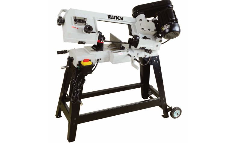
This horizontal/vertical band saw is designed to cut everything from brass and aluminum to rugged alloy and steel tools as well as plastic and wood. Features include: a vise for holding material, a pressure adjustment for gravity feed cutting in the horizontal position and vertical cutting plate.
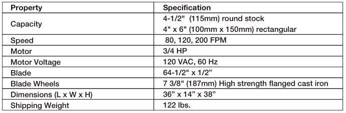
Technical Specifications
Important Safety Information
WARNING:
- Read and understand all instructions. Failure to follow all instructions may result in serious injury or property damage.
- The warnings, cautions, and instructions in this manual cannot cover all possible conditions or situations that could occur. Exercise common sense and caution when using this tool. Always be aware of the environment and ensure that the tool is used in a safe and responsible manner.
- Do not allow persons to operate or assemble the product until they have read this manual and have developed a thorough understanding of how it works.
- Do not modify this product in any way. Unauthorized modification may impair the function and/or safety and could affect the life of the product. There are specific applications for which the product was designed.
- Use the right tool for the job. DO NOT attempt to force small equipment to do the work of larger industrial equipment. There are certain applications for which this equipment was designed. It will do the job better and more safely at the capacity for which it was intended. DO NOT use this equipment for a purpose for which it was not intended.
- Industrial or commercial applications must follow OSHA requirements.
WARNING:
- This product may contain chemicals known to the State of California to cause cancer, birth defects or other reproductive harm.
- Some dust created by power sanding, sawing, grinding, drilling, and other construction activities contains chemicals known to the State of California to cause cancer, birth defects, or other reproductive harm. Some examples of these chemicals are:
- lead from lead-based paints,
- crystalline silica from bricks and cement and other masonry products, and
- arsenic and chromium from chemically-treated lumber.Your risk from these exposures varies, depending on how often you do this type of work. To reduce your exposure to these chemicals: work in a well-ventilated area, and work with approved safety equipment, such as dust masks that are specially designed to filter out microscopic particles.
- Handling power cords on corded products may expose you to lead, a chemical known to the State of California to cause cancer and birth defects or other reproductive harm. Wash your hands after handling.
WARNING:WORK AREA SAFETY
- Inspect the work area before each use. Keep work area clean, dry, free of clutter, and well lit. Cluttered, wet, or dark work areas can result in injury. Using the mini metal lathe in confined work areas may put you dangerously close to other cutting tools and rotating parts.
- Do not use the mini metal lathe where there is a risk of causing a fire or an explosion; e.g., in the presence of flammable liquids, gases, or dust. The product can create sparks, which may ignite the flammable liquids, gases, or dust.
- Do not allow the mini metal lathe to come into contact with an electrical source. The tool is not insulated and contact will cause electrical shock.
- Keep children and bystanders away from the work area while operating the tool. Do not allow children to handle the mini metal lathe.
- Be aware of all power lines, electrical circuits, water pipes, and other mechanical hazards in your work area. Some of these hazards may be hidden from your view and may cause personal injury and/or property damage if contacted.
WARNING:PERSONAL SAFETY
- Stay alert, watch what you are doing, and use common sense when operating the tool. Do not use the tool while you are tired or under the influence of drugs, alcohol, or medication. A moment of inattention while operating the tool may result in serious personal injury.
- Dress properly. Do not wear loose clothing, dangling objects, or jewelry. Keep your hair, clothing and gloves away from moving parts. Loose clothes, jewelry, or long hair can be caught in moving parts. Air vents on the tool often cover moving parts and should be avoided.
- Wear the proper personal protective equipment when necessary. Use ANSI Z87.1 compliant safety goggles (not safety glasses) with side shields, or when needed, a face shield. Use a dust mask in dusty work conditions. Also use non-skid safety shoes, hardhat, gloves, dust collection systems, and hearing protection when appropriate. This applies to all persons in the work area.
- Do not overreach. Keep proper footing and balance at all times. · Remove keys or wrenches before connecting the tool to an air supply, power supply, or turning on the tool. A wrench or key that is left attached to a rotating part of the tool may cause personal injury.
- Secure the work with clamps or a vise instead of your hand when practical. This safety precaution allows for proper tool operation using both hands.
WARNING:ELECTRICAL SAFETY
- Grounded tools must be plugged into an outlet properly installed and grounded in accordance with all codes and ordinances. Never remove the grounding prong or modify the plug in any way. Do not use any adapter plugs. Check with a qualified electrician if you are in doubt as to whether the outlet is properly grounded. If the tools should electrically malfunction or break down, grounding provides a low resistance path to carry electricity away from the user.
- Double insulated tools are equipped with a polarized plug (one blade is wider than the other). This plug will fit in a polarized outlet only one way. If the plug does not fit fully in the outlet, reverse the plug. If it still does not fit, contact a qualified electrician to install a polarized outlet. Do not change the plug in any way. Double insulation eliminates the need for the three wire grounded power cord and grounded power supply system.
- Do not allow the product to come into contact with an electrical source. The tool is not insulated and contact will cause electrical shock.
- Avoid body contact with grounded surfaces such as pipes, radiators, ranges, and refrigerators. There is an increased risk of electric shock if your body is grounded.
- Do not expose power tools to rain or wet conditions. Water entering a power tool will increase the risk of electric shock.
- Do not abuse the power cord. Never use the power cord to carry the tools or pull the plug from an outlet. Keep the power cord away from heat, oil, sharp edges, or moving parts. Replace damaged power cords immediately. Damaged power cords increase the risk of electric shock.
- When operating a power tool outside, use an outdoor extension cords marked “W-A” or “W”. These extension cords are rated for outdoor use, and reduce the risk of electric shock.
CAUTION:SAW USE AND CARE
- Do not force the saw. Tools do a better and safer job when used in the manner for which they are designed. Plan your work, and use the correct tool for the job.
- Check for damaged parts before each use. Carefully check that the tool will operate properly and perform its intended function. Replace damaged or worn parts immediately. Never operate the tool with a damaged part.
- Do not use a saw with a malfunctioning switch. Any power tool that can’ be controlled is dangerous and must be repaired by an authorized service technician before using.
- Disconnect the power/air supply from the product and place the switch in the locked or off position before making any adjustments, changing accessories, or storing the tool. Such preventive safety measures reduce the risk of starting the tool accidentally.
- Store the tool when it is not in use. Store it in a dry, secure place out of the reach of children. Inspect the tool for good working condition prior to storage and before re-use.
- Use only recommended accessories with your saw. Accessories that may be suitable for one tool may create a risk of injury when used with another tool.
- Keep guards in place and in working order. Never operate the saw without the guards in place.
- Do not leave the saw running unattended.
Specific Operation Warnings
WARNING:
- Wear the proper safety gear including ANSI Z87.1 compliant eye protection.
- Cutting Hazard. DO NOT operate with guard removed. Keep hands clear of blade.
- Hold work piece firmly against table. · Never hold the material by hand with the saw in the horizontal position. Always use the vise or clamp.
- Support long, heavy work by other methods from the floor.
- Electric shock hazard. Be sure equipment is properly grounded.
- Do not expose power tools to rain or wet conditions. Water entering a power tool will increase the risk of electric shock.
- Ground fault circuit interrupters. If work area is not equipped with a permanently installed Ground Fault Circuit Interrupter outlet (GFCI), use a plug-in GFCI between power tool or extension cord and power receptacle.
- Avoid body contact with grounded surfaces such as pipes, radiators, ranges, and refrigerators. There is an increased risk of electric shock if your body is grounded.
- Avoid accidental starting. Ensure the switch is in the off position before plugging tool into power outlet.
- In the event of a power failure, while a tool is being used, turn both the switches off to prevent surprise starting when power is restored.
- When moving the saw, ALWAYS have the head lowered to the horizontal position.
- Turn power OFF before servicing.
- Not for use by or around children.
Grounding
WARNING:
- This machine must be grounded while in use to protect the operator from electrical shock. This drill press is equipped with an electric cord that has an equipment-grounding conductor and a grounding plug. The plug MUST be plugged into a matching receptacle that is properly installed and grounded in accordance with ALL local codes and ordinances.
- DO NOT MODIFY THE PLUG PROVIDED. If it will not fit the receptacle, have the proper receptacle installed by a qualified electrician.
- CHECK with a qualified electrician or service person if you do not completely understand the grounding instructions, or if you are not sure the tool is properly grounded.
Grounded Tools: Tools with 3-Prong PlugsTools marked with Grounding Required have a 3-wire cord and 3-prong grounding plug. The plug must be connected to a properly grounded outlet. If the tool should electrically malfunction or break down, grounding provides a low resistance path to carry electricity away from the user, reducing the risk of electric shock. (See Figure A.) The grounding prong in the plug is connected through the green wire inside the cord to the grounding system in the tool. The green wire in the cord must be the only wire connected to the tool’s grounding system and must never be attached to an electrically live terminal. Your tool must be plugged into an appropriate outlet, properly installed and grounded in accordance with all codes and ordinances. The plug and outlet should look like those in the following illustration.

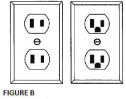
Double Insulated Tools: Tools with Two-Prong PlugsTools marked Double Insulated do not require grounding. They have a special double insulation system which satisfies OSHA requirements and complies with the applicable standards of Underwriters Laboratories, Inc., the Canadian Standard Association, and the National Electrical Code. (See Figure B.) Double insulated tools may be used in either of the 120 volt outlets shown in the following illustration.
Extension Cords
WARNING:
- USE A PROPER EXTENSION CORD. Make sure your extension cord is in good condition. When using an extension cord, be sure to use one heavy enough to carry the current your product will draw. An undersized cord will cause a drop in line voltage, resulting in loss of power and cause overheating.
- Be sure your extension cord is properly wired and in good condition. Always replace a damaged extension cord or have it repaired by a qualified person before using it. Protect your extension cords from sharp objects, excessive heat and damp or wet areas.
- Grounded tools require a 3-wire extension cord. Double Insulated tools can use either a 2- or 3-wire extension cord.
- As the distance from the supply outlet increases, you must use a heavier gauge extension cord. Using extension cords with inadequately sized wire causes a serious drop in voltage, resulting in loss of power and possible tool damage.
- The smaller the gauge number of the wire, the greater the capacity of the cord. For example, a 14-gauge cord can carry a higher current than a 16-gauge cord. Minimum extension cord wire size is shown in the following table:

- When using more than one extension cord to make up the total length, make sure each cord contains at least the minimum wire size required.
- If you are using one extension cord for more than one tool, add the nameplate amperes and use the sum to determine the required minimum cord size.
- If you are using an extension cord outdoors, make sure it is marked with the suffix W-A (W in Canada) to indicate it is acceptable for outdoor use.
- Make sure your extension cord is properly wired and in good electrical condition. Always replace a damaged extension cord or have it repaired by a qualified electrician before using it.
- Protect your extension cords from sharp objects, excessive heat, and damp or wet areas.
Assembly
WARNING:Use an appropriate lifting device to lift and hold the band saw base securely as it weights approximately 100 lbs.
Assembling the Band Saw
- With the help of an assistant, lift the band saw onto a suitable support.
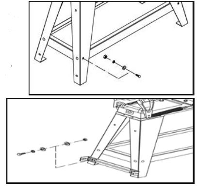
- Attach the legs to the band saw with M8-1.25×25 hex bolts, 8mm flat washers, 8mm lock washers, and M8-1.25 hex nuts.
- Attach the short brace to the legs with the M6-1.0×16 carriage bolts, 6mm flat washers, 6mm lock washers, and M6-1.0 hex nuts.
- Lift the band saw onto the floor and attach the long brace to the legs with the M6-1.0×16 carriage bolts, 6mm flat washers, 6mm lock washers, and M6-1.0 hex nuts.
- Use the M6-1×12 hex bolts, M6-1 hex nuts, 6mm lock washers, and 6mm flat washers to install the wheel mounting bracket to the legs.
- Slide the shaft through the holes in the wheel mounting bracket. Slide the wheels onto the shaft on the outside of the mounting bracket, and secure them with cotter pins.
- For the legs on the other side, insert the handle into the pre-drilled holes and secure it with the cotter pins.
- Check if the band saw is relatively level, and then tighten all the nuts.
- Remove the screws and washers from the band saw. Place the belt house over the motor and gear shafts, and secure it with the removed screws and washers.
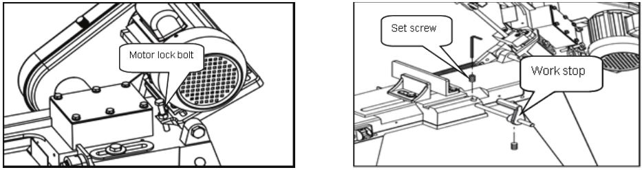
- Open the pulley cover and install the key and motor pulley to the motor shaft. Install the worm gear pulley on the shaft closest to the gear box. Use a straightedge to check the alignment of the pulley wheels, and adjust them as needed.When the pulley wheels are aligned, tighten the set screws on both pulleys and install the V belt. The belt tension can be adjusted by adjusting the motor lock bolt.
- Install the work stop shaft into the side of the band saw and lock it in place by tightening the set screw. Slide the work stop onto the end of the shaft and lock it into position with the set screw.


Vice Adjustment
- Loosen the two hex bolts.
- Use the scale as a guide to set your angle.
- Tighten the hex bolts.
- Loosen the hex bolt on the opposite jaw so the jaw can float, then match the angle of the workpiece and retighten the hex bolt.
- Tighten the vise against the workpiece.

Feed Rate Adjustment
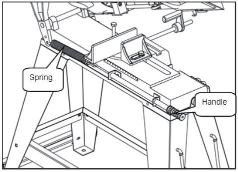
The feed rate is controlled by the spring and handle. To adjust the feed rate:
- Slower: twist the handle clockwise to add tension to the spring.
- Faster: twist the handle counter-clockwise to remove tension from the spring.
Head Lock PinThe head locking pin safely secures the head in the down position. To ensure the head does not unexpectedly spring up and tip the band saw over, this locking pin must be properly inserted when the band saw is not in use or before moving it.
To use the head locking pin:Lower the head all the way down, then insert the locking pin through the holes in the head pivot arm and base.

Before Each Use
- Check for damaged parts before each use. Carefully check that the tool will operate properly and perform its intended function. Replace damaged or worn parts immediately. Never operate the tool with a damaged part.
- Do not use a tool with a malfunctioning switch. Any power tool that cannot be controlled with the power switch is dangerous and must be repaired by an authorized service technician before use.
- Inspect the work area before each use. Keep work area clean, dry, free of clutter, and well lit. Cluttered, wet, or dark work areas can result in injury. Using the saw in confined work areas may put you dangerously close to other cutting tools and rotating parts.
Operating Instructions
WARNING:
- Use only recommended parts with the saw. Parts that may be suitable for one tool may create a risk of injury when used with another tool. Never use an accessory that has a lower maximum operating speed than the machine.
- Keep guards in place and in working order. Never operate the saw without the guards in place.
- Do not leave the saw running unattended.
- Always remember to turn off the saw when the work is completed.
- In the event of a power failure while the saw is being used, turn the power switch to OFF to prevent surprise starting when power is restored.
- Put the switch in the locked or off position before making any adjustments, changing accessories, or storing the saw to avoid the risk of starting the saw accidentally.
- Ensure the power switch is in the off position before plugging the saw into a power outlet to avoid accidental starting.
- Always check to ensure the power supply corresponds to the voltage on the rating plate.
- Always use push sticks, particularly when cutting small pieces.
WORK SET UP
- Raise the saw head to the vertical position.
- Open the vise to accept the piece to be cut by rotating the wheel at the end of base (counterclockwise).
- Place the workpiece on the saw bed. If the piece is long, support the end by other means.
- Clamp the workpiece securely in the vise by rotating the hand wheel clockwise.
VERTICAL CUTTING PLATE ASSEMBLY
Note: These steps are only necessary if using the band saw in the vertical mode.
WARNING:Disconnect the saw from the power source before making any repairs or adjustments.
- Loosen the screws (A and B ) from the blade guide. Remove part D.
- Raise the cutting head to the vertical position. Install the safety bracket and lock it in place with the pin to keep the saw from falling.

- Place the table on the guide then tighten screws A and B. Assemble the vertical cutting plate stand with the preinstalled hex bolt, the flat head screw C, and hex nut.
- Operate vertical cutting using the miter gauge in the cutting plate groove to obtain any angle up to 45 degrees either left or right.


CHANGING SPEEDS
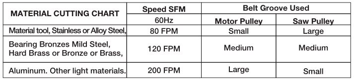
When using your band saw, always change the blade speed to best suit the material being cut. See the cutting chart shown below.
- Turn off power.
- Open the belt guard cover (75).
- Loosen the motor lock bolt (#70), you are now able to change the position of the belt on the two pulleys to obtain the desired speed.
- When belt is adjusted, lock the motor firmly.
- Close the belt guard cover.
CUTTING
CAUTION: NEVER OPERATE THE SAW WITHOUT BLADE GUARDS IN PLACE.Be sure the blade is not in contact with the work when the motor is started. Start the motor, allow the saw to come to full speed, and then begin the cut by lowering the head down slowly onto the work. DO NOT DROP OR FORCE the blade. Let the weight of the saw head provide the cutting force. The saw automatically shuts off at the end of the cut.
Adjusting the blade:
- A. Loosen the screw (1, shown at right).
- B. Adjust the blade adjustable seat (2) to make the blade vertical to the bed.
- C. Place a square on the bed to check that the blade is vertical. If not, repeat step B.
- D. Tighten the screw (1).
BLADE SELECTION
A general-use blade is furnished with the saw. Additional blades in 10 and 14 tooth sizes are available. The choice of blade pitch is governed by the thickness of the work to be cut; the thinner the workpiece, the more teeth recommended. A minimum of 3 teeth should be in the workpiece at all times for proper cutting. If the teeth of the blade are so far apart that they straddle the work, severe damage to the workpiece and to the blade can result.
BLADE DIRECTION OF TRAVEL
Be sure the blade is assembled to the pulleys such that the vertical edge engages the workpiece first.
CHANGING BLADES
- Ensure that power is disconnected before changing the blade.
- Raise the saw head to vertical.
- Remove the screw (113) and washer(114), open the blade back safety cover(115).
- Loosen the blade tension adjusting knob (37) sufficiently to allow the saw blade to slip off the wheels.
- Wearing gloves, carefully install the new blade with teeth slanting toward the motor (shown above) as follows:
- a. Place the blade in between each of the guide bearings.
- b. Slip the blade around the lower wheel with the left hand and hold it in position.
- c. Hold the blade taut against the lower wheel by pulling the blade upward with the right hand placed at the top of the blade.
- d. Remove the left hand from lower wheel and place it at the top side of the blade to continue the upward pull on the blade.
- e. Remove the right hand from blade and adjust the position of the upper wheel to permit the left hand to slip the blade around the wheel, using the thumb, index and little finger as guides.
- f. Adjust the blade tension knob clockwise until it is just right enough so no blade slippage occurs. Do not tighten excessively.
- Close the back safety cover and replace the screw and washer.
BLADE GUIDE ADJUSTMENT
This metal cutting band saw is equipped with an adjustable blade guide. This feature permits you to adjust the position of the blade guide for variable width workpieces. To get the most accurate cut and prolong the life of the blade, the adjustable blade guide should be adjusted to just clear the piece to be cut. This is done as follows:
- Place the workpiece in the vise.
- Adjust the blade guide to the desired position by loosening the hand knob (49) and positioning the guide as required.
- Tighten the hand knob.
ADJUSTING BLADE TENSION
- Ensure that power is disconnected before adjusting the blade tension.
- Press the blade lightly half-way between the wheels with left hand. The blade should bow about 1 mm.
- Adjust the blade tension adjusting knob (37) with the right hand until proper tension is obtained.
BLADE GUIDE BEARING ADJUSTMENT
This is the most important adjustment on the saw. It is impossible to get satisfactory work from your saw if the blade guides are not properly adjusted. The blade guide bearing for your band saw are adjusted and power tested with several test cuts before leaving the factory to insure the proper setting.The need for adjustment should rarely occur if the saw is used properly. If the guides become out of adjustment, it is extremely important to readjust immediately. If proper adjustment is not maintained, the blade will not cut straight and if the situation is not corrected, it will cause blade damage. Because guide adjustment is a critical factor in the performance of your saw, it is always best to try a new blade to see if this will correct poor cutting before beginning to adjust the bearings. If a blade becomes dull on one side sooner than the other, for example, it will not cut straight. A simple blade change should correct this problem, the more difficult guide adjustment will not. If a new blade does not correct the problem, check the blade guides for proper spacing. There should be 0.001″ clearance between the 0.025″ thickness blade and guide bearing. The inner guide bearing is fixed and cannot be adjusted. The outer guide bearing is mounted to the idler pulley shaft (93 & 106) and can be adjusted. To obtain this clearance, adjust as follows:
- Loosen the nut while holding the bolt with a wrench.
- Position the eccentric by turning the bolt to the desired position of clearance.
- Tighten the nut.
- Adjust the second blade guide bearing in the same manner.
- The back edge of the blade should just touch the lip of the blade guide bearing.
ADJUSTING THE BLADE TRACKING
This adjustment has been completed and tested at the factory. The need for adjusting should rarely occur when the saw is used properly. If tracking becomes out of adjustment, use the steps below to correct it:
- Turn the blade tension knob (37) to loosen the blade a little while it still tracks against the pulley.
- Loosen the hex head screws (24).
- Simultaneously turn with blade tension knob (37) and the hex head screw (25) to align the blade with the edge of the pulley.
- Tighten the hex head screw (24) to secure tracking then tighten the blade tension knob to correct tension.
- Adjust the blade guides according to the material size (see Blade Guide Adjustment).
After Each Use
After each use, clean the saw of debris and scraps of metal. If the saw will not be used for a while, spread a thin coat of oil on the surfaces that not painted to prevent rust.
Store the saw when it is not in use. Store it in a dry, secure place out of the reach of children. Inspect the saw for good working condition prior to storage and again before re-use.
Maintenance
WARNING:
- Put the switch in the locked or off position before making any adjustments, changing accessories, or storing the tool to avoid the risk of starting the saw accidentally.
- Use only recommended parts for use with the saw. Parts that may be suitable for one tool may create a risk of injury when used with another tool. Never use an accessory that has a lower operating speed than the saw itself.
Maintain the saw. It is recommended that the general condition of any tool be examined before it is used. Keep the saw in good repair by adopting a program of conscientious repair and maintenance in accordance with the recommended procedures found in this manual. Keep all cutting tools sharp and clean. Properly maintained cutting tools with sharp cutting edges are less likely to bind and are easier to control. Keep handles dry, clean, and free from oil and grease.
Parts Diagram
Parts List
 Parts List


Troubleshooting

Replacement Parts
- For replacement parts and technical questions, please call Customer Service at 1-800-222-5381.
- Not all product components are available for replacement. The illustrations provided are a convenient reference to the location and position of parts in the assembly sequence.
- When ordering parts, the following will be required: Model Number, Serial Number/Lot Date Code, and Description.
- The distributor reserves the rights to make design changes and or improvements to product lines and manuals without notice.
Limited Warranty
Northern Tool and Equipment Company, Inc. (“We” or ‘”Us”) warrants to the original purchaser only (“You” or “Your”) that the Ironton Air Tool product purchased will be free from material defects in both materials and workmanship, normal wear and tear excepted, for a period of one year from date of purchase. The foregoing warranty is valid only if the installation and use of the product is strictly in accordance with product instructions. There are no other arranties,express or implied, including the warranty of merchantability or fitness for a particular purpose.If the product does not comply with this limited warranty, Your sole and exclusive remedy is that We will, at our sole option and within a commercially reasonable time, either replace the product without charge to You or refund the purchase price (less shipping). This limited warranty is not transferable.
Limitations on the WarrantyThis limited warranty does not cover: (a) normal wear and tear; (b) accessories both consumable and durable; (c) damage through abuse, neglect, misuse, or as a result of any accident or in any other manner; (d) damage from misapplication, overloading, or improper installation; (e) improper maintenance and repair; and (f) product alteration in any manner by anyone other than Us, with the sole exception of alterations made pursuant to product instructions and in a workmanlike manner.
Obligations of PurchaserYou must retain Your product purchase receipt to verify date of purchase and that You are the original purchaser. To make a warranty claim, contact Us at 1-800-222-5381, identify the product by make and model number, and follow the claim instructions that will be provided. The product and the purchase receipt must be provided to Us in order to process Your warranty claim. Any returned product that is replaced or refunded by Us becomes our property. You will be responsible for return shipping costs or costs related to Your return visit to a retail store.
Remedy LimitsProduct replacement or a refund of the purchase price is Your sole remedy under this limited warranty or any other warranty related to the product. We shall not be liable for: service or labor charges or damage to Your property incurred in removing or replacing the product; any damages, including, without limitation, damages to tangible personal property or personal injury, related to Your improper use, installation, or maintenance of the product; or any indirect, incidental or consequential damages of any kind for any reason.
Assumption of RiskYou acknowledge and agree that any use of the product for any purpose other than the specified use(s) stated in the product instructions is at Your own risk.
Governing LawThis limited warranty gives You specific legal rights, and You also may have other rights which vary from state to state. Some states do not allow limitations or exclusions on implied warranties or incidental or consequential damages, so the above limitations may not apply to You. This limited warranty is governed by the laws of the State of Minnesota, without regard to rules pertaining to conflicts of law. The state courts located in Dakota County, Minnesota shall have exclusive jurisdiction for any disputes relating to this warranty.
![]()
Distributed byNorthern Tool and Equipment Company, Inc.Burnsville, Minnesota 55306NorthernTool.comMade in China
[xyz-ips snippet=”download-snippet”]