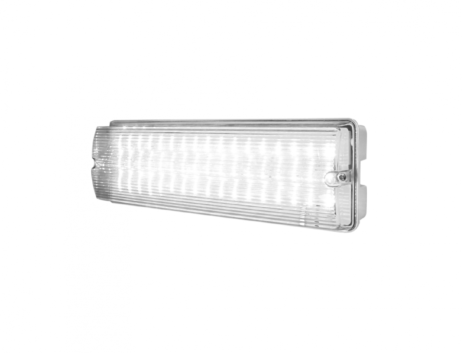
Knightsbridge EMLED1 LED Emergency Bulkhead
GENERAL INSTRUCTIONS
These instructions should be read carefully and retained after installation by the end user for future reference and maintenance.These instructions should be used to aid installation of the following product: EMLED1
SAFETY
- Installation of this luminaire should only be carried out by a qualified electrician or competent person to the latest Building and current IEE Wiring Regulations (BS7671)
- Please isolate mains prior to installation/maintenance
- Check the total load on the circuit (including when this luminaire is fitted) does not exceed the rating of the circuit cable, fuse or circuit breaker
- Please note the IP (Ingress of Protection) rating of this luminaire when deciding the location for installation
- Initial commissioning test – We recommend a minimum charge period of 24 hours before completing an initial commissioning emergency duration test
- This product is Class I and requires an earth
- This product is non-dimmable
- This product is IP65 rated
INSTALLATION
- Provide power to the required point of installation, Please note the IP (Ingress of Protection) rating of this luminaire when deciding the location for installation
- Remove the screws at each end of the product to remove the diffuser
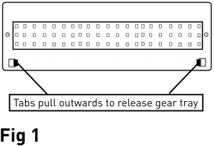
- Release the gear tray by pushing the release tabs outwards of the fitting see (Fig 1)

- Mark the location of the fixing holes and drill the holes ensuring not to infringe with any joists, gas/water pipes or electrical cables
- Make a 20mm hole in the required marked location on the fitting for mains cable entry
- Feed the cable through the fitting using an appropriate compression gland or rubber grommet to ensure IP rating is maintained
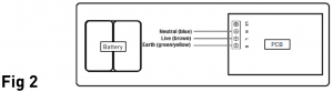
- For non-maintained operation, carefully wire as shown in Fig 2
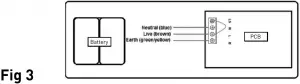
- For maintained operation, carefully wire a link between Live (L) and Switched Live (LS), as shown in Fig 3
- For maintained non-switched operation, carefully wire as shown in Fig 4
- Connect the battery to the inverter via the plug and socket provided
- Refit the gear tray by pushing down until the tabs click into place
- Place diffuser in line with the 2 screw holes and fasten screws down
- Switch on the power supply and ensure the LED indicator is illuminated Green.If it is not illuminated Green, there may be a battery fault
- A self-adhesive legend kit has been supplied with this product should it be required

WARNING
This product must be disconnected from the circuit if subjected to any high voltage or insulation resistance testing. Irreparable damage will occur if this instruction is not followed.
GENERAL
The LEDs fitted in this product are non-replaceable. The unit should be recycled in the correct manner when it reaches the end of its life. Check local authorities for where facilities exist.Clean with a soft dry cloth only, do not use aggressive cleaning products or solvents which may damage the fitting.
WARRANTY
This product has a warranty of 3 years (excluding the battery) from date of purchase. Failure to install this product in accordance with the current edition of the IEE Wiring Regulations, improper use, or removal of the batch codes will invalidate the warranty. If this product should fail within its warranty period it should be returned to the place of purchase for a free of charge replacement.ML Accessories does not accept responsibility for any installation costs associated with the replacement product. Your statutory rights are not affected. ML Accessories reserve the right to alter product specification without prior notice.
TESTING FOR EMERGENCY LUMINAIRES
Recommended routine test procedure in accordance with BS5266.
Initial commissioning test – We recommend a minimum charge period of 24 hours before completing an initial commissioning emergency duration test
Daily check – check that the status GREEN LED indicator is illuminated.
Monthly functional test – simulate a mains supply failure for approx. 30 secs by operation of key switch or switching off a circuit breaker. Ensure normal supply is restored after test and the indicator status LED is illuminated.
Annual full three hour duration test – conduct a three hour continuous duration test. Simulate a mains supply failure for three hour continuous test by operation of key switch or switching off circuit breaker. Ensure normal supply is restored after test and the indicator status LED is illuminated.
If the luminaire fails any of the above tests, please contact a qualified electrician.
|
TEST RECORD SHEET |
|||||||||||
|
INITIAL COMMISSIONING 3 HOUR TEST |
SIGNED |
DATE |
|||||||||
|
MONTH |
TEST |
FIRST YEAR |
SECOND YEAR | THIRD YEAR | FOURTH YEAR |
FIFTH YEAR |
|||||
| SIGNED | DATE | SIGNED | DATE | SIGNED | DATE | SIGNED | DATE | SIGNED |
DATE |
||
|
1 |
FUNCTIONAL |
||||||||||
|
2 |
FUNCTIONAL |
||||||||||
|
3 |
FUNCTIONAL |
||||||||||
|
4 |
FUNCTIONAL |
||||||||||
|
5 |
FUNCTIONAL |
||||||||||
|
6 |
FUNCTIONAL |
||||||||||
|
7 |
FUNCTIONAL |
||||||||||
|
8 |
FUNCTIONAL |
||||||||||
|
9 |
FUNCTIONAL |
||||||||||
|
10 |
FUNCTIONAL |
||||||||||
|
11 |
FUNCTIONAL |
||||||||||
|
12 |
3 HOUR |
Installed by:________________.
Installation date:_______________.
Contact number:________________.


References
[xyz-ips snippet=”download-snippet”]