
![]()
SCAN ME https://l.ead.me/bboAirA STEP-BY-STEP VIDEO ON HOW TO ASSEMBLE & THE TOOLS NEEDEDITEM #236877848-IN 2-DOOR CABINETMODEL#0019000
ATTACH YOUR RECEIPT HERESerial NumberPurchase DateQuestions, problems, missing parts?Before returning to your retailer, call our customer service department at 1-888-3KOBALT (1-888-356-2258), 8 a.m. – 8 p.m., EST,VR20212
PRODUCT SPECIFICATIONS
|
COMPONENTS |
SPECIFICATIONS |
| Maximum load for each hook | 2 lbs. |
| Maximum load for each door | 11 lbs. |
| Maximum load for back panels | 22 lbs. |
| Maximum load for a bottom shelf | 150 lbs. |
| Maximum load for adjustable shelf | 150 lbs. |
| Maximum total load | 644 lbs. |
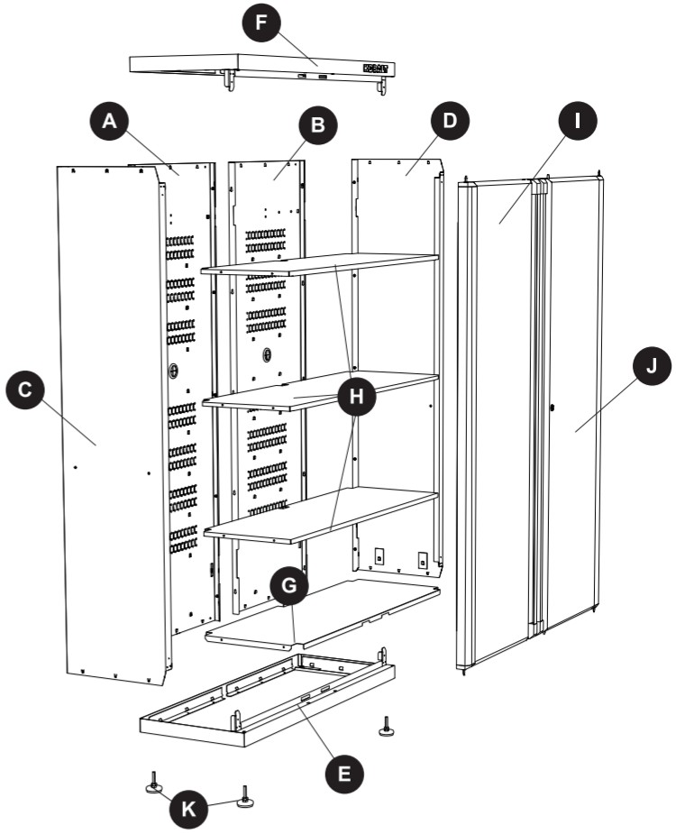
PACKAGE CONTENTS
| PART | DESCRIPTION | QUANTITY |
| A | Left-back panel | 1 |
| B | Right-back panel | 1 |
| C | Left side panel | 1 |
| D | Right side panel | 1 |
| E | Base panel | 1 |
| F | Top panel | 1 |
| G | Bottom shelf | 1 |
| H | Adjustable shelf | 3 |
| I | Left door | 1 |
| J | Right door | 1 |
| K | Leg leveler assembly | 4 |
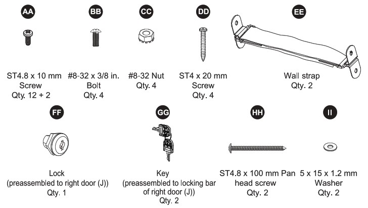
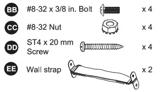
HARDWARE CONTENTS (shown actual size)
 SAFETY INFORMATION
Please read and understand this entire manual before attempting to assemble or operate this product. Failure to follow may result in serious injury. Save all warnings and instructions for future reference.![]() WARNING
WARNING
- Do not stand on, step on, or alter this unit for anything outside the designed function of storage.
- Use care when handling and assembling metal plates.
- The metal may have sharp edges or corners. The use of protective gloves is recommended.
- Close and lock the doors before moving this product.
- It is always recommended to secure this product to the wall with the hardware provided.
- Always remember to use proper lifting techniques when moving the boxed or assembled unit.
SAFETY INFORMATION
CAUTION
- Do not exceed maximum load capacities listed in Product Specifications on Page 2.
- When storing articles, equally distribute loads. Always balance the loads to avoid tipping.
- Place more than half the total load weight on the bottom cabinet when possible.
- Keep the product on level surfaces. The product may become unstable and it may tip over if stored or moved on an uneven surface, which may cause personal injury or product damage.
- Do not store flammable liquids in the unit unless they are secured in an approved container.
- Do not store gasoline in the unit under any circumstances.
- Do not leave children unattended near this product. Cabinet may tip over if improperly opened.
- Always use common sense and be cautious when using this product.
PREPARATION
Before beginning the assembly of the product, make sure all parts are present. Compare parts with package contents list and hardware contents above. If any part is missing or damaged, do not attempt to assemble the product. Contact customer service for replacement parts. It is recommended that this product be assembled on a clean, soft surface, such as a piece of cardboard.Estimated Assembly Time: 30 minutes (does not include unpacking time)Tools Required for Assembly (not included): Drill, PH2 screwdriver, Rubber mallet, Adjustable wrench
ASSEMBLY INSTRUCTIONS
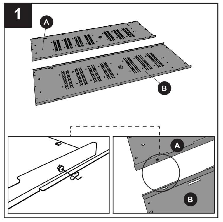
- Slide preassembled screws in left-back panel (A) into key slots of right back panel (B) to connect the two back panels together. Tighten the screws.Note: Be sure to keep the back panels on a soft surface, such as carpeting or a piece of cardboard, to protect them from scratches.
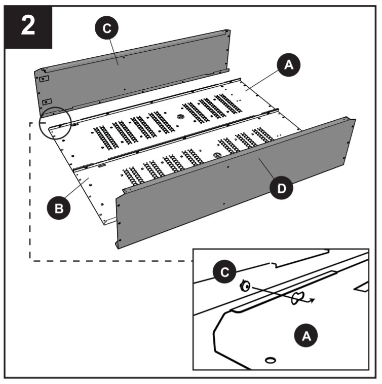
- Slide preassembled screws into key slots of the assembled unit from Step 1 to connect the left side panel (C) and right-side panel (D) to the assembled unit. Tighten the screws.
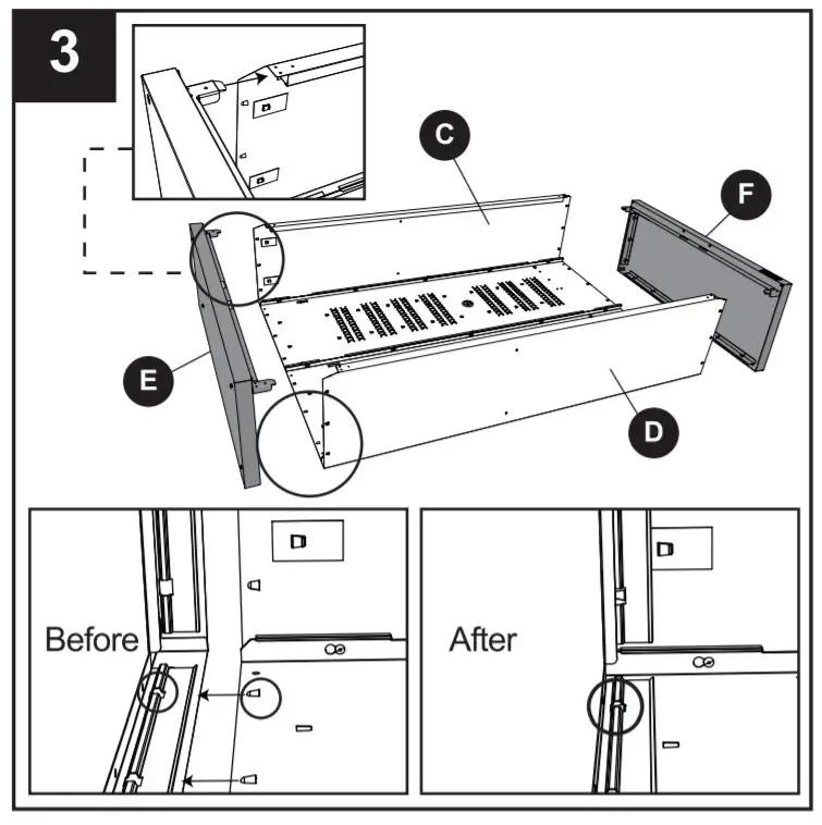
- Align the base panel (E) with the assembled unit from Step 2 carefully. Tap the base panel (E) into the unit until the clips are secured tightly. Repeat this step to attach the top panel (F) to the assembled unit.Note: Recommended to use a rubber mallet to tap the components together.
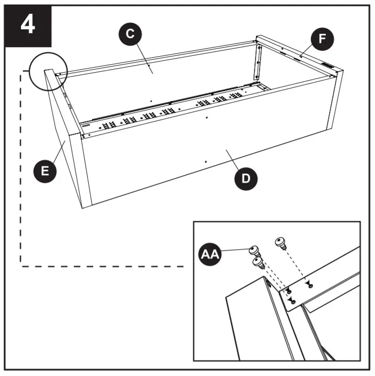
- Check and verify the holes in the front edge of the base panel (E) and top panel (F) are aligned with the holes in the left side panel (C) and right-side panel (D). If not, check and make sure the base panel (E) and top panel (F) are located in the right place. Tighten the ST4.8 x 10 mm screws (AA) to the holes to make the unit securely fixed.Hardware Used
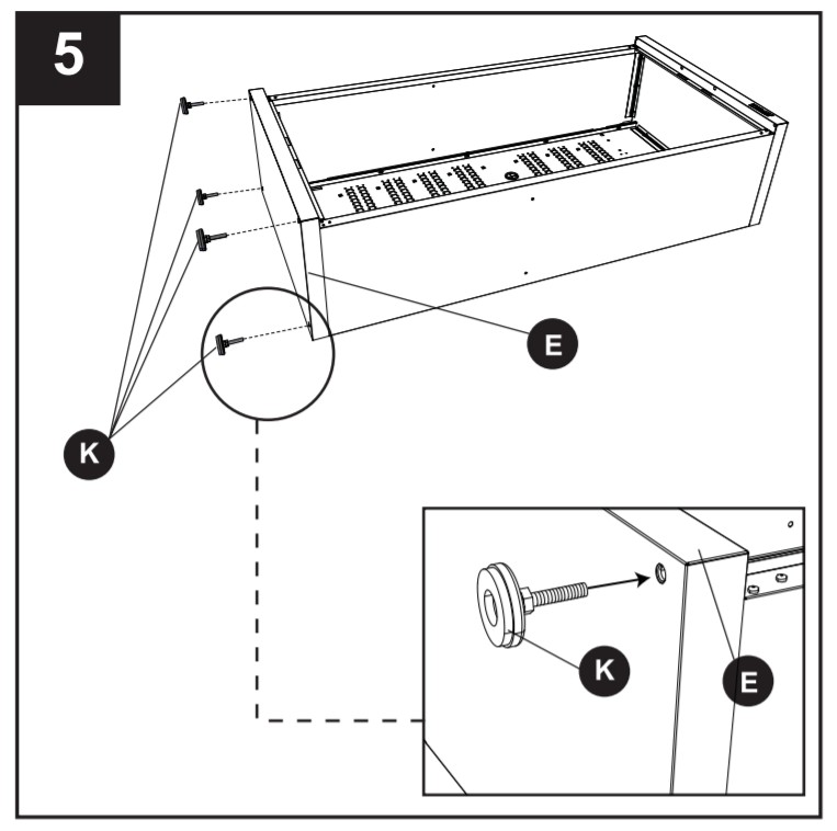
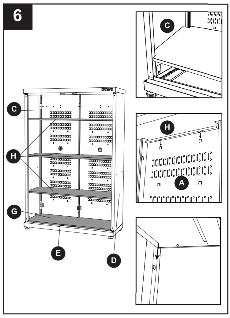
- Screw leg leveler assemblies (K) to base panel (E) until tight. Place the cabinet upright.
- Install the bottom shelf (G) by tipping it to the side and inserting it into the cabinet. With the bottom shelf (G) at an angle, align the cut-outs on the bottom shelf (G) with the back seams caused by side panels (C and D) and back panels (A and B). Carefully lower the bottom shelf (G), ensuring the front of the bottom shelf (G) goes over the front flange of the base panel (E).Determine the location for the other 3 adjustable shelves (H). Hold the adjustable shelves (H) at an angle to make them easier to install. Repeat the above method to install. Please make sure adjustable shelf (H) snaps into the hooks on the unit.Note: If the hooks are flatted during assembly, use a slotted screwdriver (not included) to recover them.
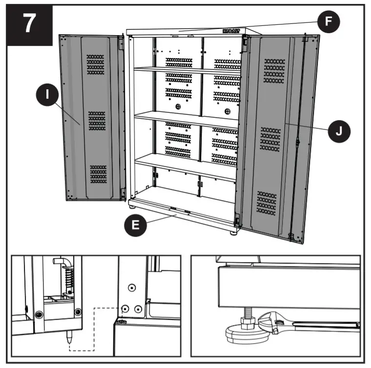
- Lift and pull the L-shaped pivot pin on the edge of the left door (I), aligning the assembling holes of the base panel (E) and top panel (F), then release. Repeat for the right door (J).Note: Check and see if the top panel (F) is level. If not level due to uneven floor, the two doors will probably not be properly aligned. In this case, use an adjustable wrench (not included) to adjust the hex nut until the top panel (F) is level.
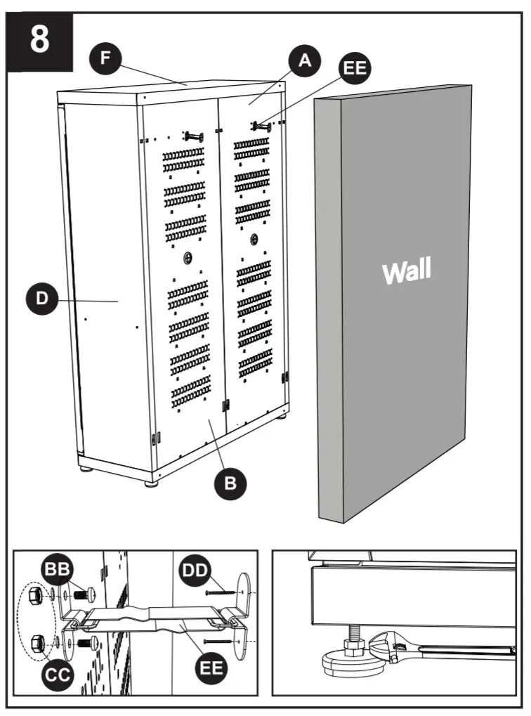
- Screw one end of wall strap (EE) to the right-back panel (B) with #8-32 x 3/8 in. bolts (BB) and #8-32 nuts (CC). Secure the other end to the wall with ST4 x 20 mm screws (DD). Repeat for another wall strap (EE).Note: This cabinet should be anchored to the wall using the wall strap (EE) to avoid any potential danger from the cabinet falling. Check and see if the top panel (F) is level. If not level due to uneven floor, the two doors will probably not be properly aligned. In this case, use an adjustable wrench (not included) to adjust the hex nut until the top panel (F) is level.Hardware Used
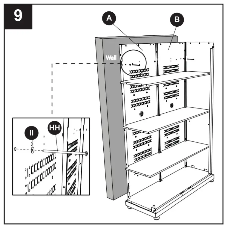
- Move the unit to the wall, making sure the back of the unit is flush with the wall. Feed the ST4.8 x 100 mm pan head screws (HH) through the 5 x 15 x 1.2 mm washers (I) and back panels (A and B). Screw the ST4.8 x 100 mm pan head screws into wall studs, and tighten securely.

 Move the unit to the wall, making sure the back of the unit is flush with the wall. Feed the ST4.8 x 100 mm pan head screws (HH) through the 5 x 15 x 1.2 mm washers (I) and back panels (A and B). Screw the ST4.8 x 100 mm pan head screws into wall studs, and tighten securely.
Note: Screws must be placed into the wall studs. The unit will not be secured if screwed into drywall. If there is a gap between the unit and the wall due to molding on the garage floor, please make the unit press against the molding and be parallel to the wall.Hardware Used
 TROUBLESHOOTING
| PROBLEM | POSSIBLE CAUSE |
CORRECTIVE ACTION |
| Screw(s) will not align into the hole(s).
|
1. Natural properties of sheet metal cause slight changes in pre-drilled hole location. | 1. Place screws into all aligned holes and hand tighten, Push a 3/8 in. hole-punch through both holes to force the alignment. With the hole punch in place, tighten all other screws. When the hole punch is removed, the screw(s) should easily fit into the remaining hole(s). |
| Doors are not probably aligned.
|
1. Uneven floor.
|
1. Adjust the hex nut in the leg leveler assembly until the doors are aligned. |
LIFETIME HASSLE-FREE GUARANTEE. This product carries a lifetime warranty. If the product is found to be defective, please call 1-888-3KOBALT, 8 a.m. -8 p.m., EST, Monday – Sunday, or return the item to the place of purchase with a copy of the original sales receipt. The distributor will, at its option, repair or replace the product. This warranty gives you specific legal rights, and you may have other rights that vary from state to state.
REPLACEMENT PARTS LIST
For replacement pas, call our customer service at -866-9KOBALT, 8 am -® pm. EST, Monday-Sunday
| PART | DESCRIPTION | PART # |
| A | Left-back panel | 2368778-A |
| B | Right-back panel | 2368778-B |
| C | Left side panel | 2368778-C |
| 13 | Right side panel | 2368778-13 |
| E | Base panel | 2368778-E |
| F | Top panel | 2368778-F |
| G | Bottom shell | 2368778-G |
| H | Adjustable shelf | 2368778-H |
| I | Left door | 2368778-I |
| J | Right door | 2368778-J |
| K | Leg leveler assembly | 106453-K |
| R | Door magnet | 106453-R |
| S | Door L shape pivot pin & spring | 106453-PS |
| T | Rubber grommet | 106453-RG |
| AA | ST4.8 x 10 mm Screw | 2368778-H0M |
| BB | #8-32 x 3/8 in. Bolt | 2368776HOWR |
| CC | #8-32 Nut | 236877611DWR |
| DD | ST4 x 20 mm Saw | 23687761MR |
| EE | Wall strap | 106453-WS |
| FF | Lock | 106453-LK |
| GG | Key | 106453-LK |
| HH | ST4.8 x 100 mm Pan’s head screw | 2368776KM |
| II | 5x 15 x 1.2 mm Washer | 23138778HOWE |
Printed in Cambodia
KOBAIS and logo designs are trademarks or registered trademarks of LC. LLC. All rights reserved.
[xyz-ips snippet=”download-snippet”]