
MAGNETIC FLYWHEEL UPRIGHT EXERCISE BIKE(EXR-500)FSM FEXR500AUSER GUIDE
SAFETY & WARNINGS
- Read all of the instructions in this guide before using this product. Retain this guide for future reference. Do not skip, substitute or modify any steps or procedures in this guide, as doing so could result in personal injury or product damage.
- Before starting any exercise program, consult your physician to determine if you have any medical or physical conditions that could put your health and safety at risk or prevent you from using the equipment properly. Your physician’s advice is essential if you are taking any medication that may affect your heart rate, blood pressure, or cholesterol level.
- Incorrect or excessive exercise can damage your health. Stop exercising if you experience any of the following symptoms: pain, tightness in your chest, irregular heartbeat, shortness of breath, lightheadedness, dizziness, or feelings of nausea. If you experience any of these conditions, you should consult your physician before continuing with your exercise program.
- This equipment is intended for adult use only. Keep children and pets away from the machine. DO NOT leave children unattended in the same room with the equipment.
- This appliance is designed for consumer use. Follow directions and use only as described.
- Once fully assembled, inspect to ensure all hardware parts such as bolts, nuts, and washers are positioned correctly and tightly secured.
- Always inspect the safety chain guard that protects the moving parts of the bike to be in safe and good order.
- Always inspect the seat, seat slider, and grips to make sure they are in a safe and stable position before using the bike.
- It is recommended to lubricate all moving parts on a monthly basis.
- Do not wear loose clothing while riding.
- Dry after each use to remove moisture. Wipe regularly with a mild, non-abrasive cleaner and water solution. To avoid damaging the finish, never use a petroleum based solvent.
- Use the equipment on a solid, flat-level surface with a protective cover for your floor or carpet. To ensure safety, the equipment should have at least 2 feet (approximately 60 cm) of free space on each side.
- Prior to assembly, ensure you have all the components and tools listed. Some components are pre-assembled to help with the assembly process.
- Always use the equipment as intended. If you find any defective components while assembling or checking the equipment, or if you hear any unusual noises coming from the equipment during exercise, cease use immediately and contact help.kogan.com for assistance. Do not use until resolved.
- Do not place fingers or any other objects into moving parts of the exercise equipment.
- Do not exceed the maximum user weight of 120 KG.
- Be careful when lifting and moving the equipment. Always use proper lifting techniques and seek assistance if necessary.
- Your equipment is intended for use in cool, dry conditions. You should avoid storage in extreme cold, hot or damp areas as this may lead to corrosion and other related problems.
- Operating temperature: 0-40 °C
- Storage temperature: -10- 60°C
- This appliance contains no user-serviceable parts. If it suffers any failure or damage, cease use immediately and contacthelp.kogan.com
- This equipment is designed and intended for indoor use only.
OVERVIEW
Part List
| Part | Description | Qty. | Part | Description | Qty. |
| 1 | Main Frame | 1 | 26 | Sensor Wire L=450mm | 1 |
| 2 | Handlebar | 1 | 27 | Seat Cushion | 1 |
| 3 | Handlebar Post | 1 | 28 | End Cap for Front Stabilizer | 2 |
| 4 | Rear Stabilizer .60×1.5 | 1 | 29 | End Cop for Rear Stabilizer | 2 |
| 5 | Magnetic Wheel | 1 | 30 | Belt Pulley | |
| 6 | Front Stabilizer o60x1.5 | 1 | 31 | Magnetic Wheel Axle | 1 |
| 7 | Tension Control Knob | 1 | 32 | Arc Washer oexol6x1.5 | 2 |
| 8 | Seat Height Adjustment Knob M16 | 1 | 33 | Cross Pan Head Screw M5x10 | 2 |
| 9 | Belt 380/J6 | 1 | 34 | Cap Nut M8 | 4 |
| 10 | Display | 1 | 35 | Bolt M8x65 | 4 |
| 11 | Spring ol5x55x83.0 | 1 | 36 | Arc Washer 08xo20x1.5 | 8 |
| 12 | Seat Post Plastic Bushing | 1 | 37 | Flat Washer m8xml6x1.5 | 4 |
| 13 | Left Chain Cover | 1 | 38 | Crank 6″ | 1 |
| 14 | Rat Washer oexolexl.0 | 1 | 39 | Right Chain Cover | 1 |
| 15 | Ring 017 | 2 | 40 | Cross Pon Head Tapping Screw ST4.2×25 | 8 |
| 16 | Bearing 6003Z | 2 | 41 | Hexagon Bolt MG | 2 |
| 17 | Hexagon Bolt M6x18 | 4 | 42 | Nylon Nut M8 | 4 |
| 18 | Spring Washer to | 2 | 43 | Flange Nut M10x1.0 | 2 |
| 19 | Crank Cover 1 | 2 | 44 | Pressure Plate | 1 |
| 20 | Left Foot Pedal (1/21 | 1 | 45 | Pressure Roller e43xo34x24 | 1 |
| 21 | Right Foot Pedal (1/21 | 1 | 46 | Arc Washer o5 | 1 |
| 22 | U-Shape Bracket | 2 | 47 | Spring Washer 06 | 1 |
| 23 | Eyebolt M6x36 | 2 | 48 | Nylon Nut M6 | 4 |
| 24 | Hexagon Bolt M8x15 | 6 | 49 | End Cap for Handlebar | 2 |
| 25 | Seat Post | 1 | 50 | Handlebar Foam Grip o21xm38x510 | 2 |
| 51 | Cross Pan Head Tapping Screw ST4.2×20 | 4 | 60 | Crank Cover | 2 |
| 52 | Cross Pan Head Screw M6x10 | 1 | 61 | Flat Washer .10xo25x2.0 | 1 |
| 53 | Hand Pulse Sensor Wire | 2 | 62 | Knob M10 | |
| 54 | Tension Cable | 1 | 63 | Square End Cop 38×38 | 2 |
| 55 | Hexagon Bolt M8x20 | 1 | 64 | Adjusting Pin | 2 |
| 56 | Cross Pan Head Self-Drilling Screw ST4.2×25 | 4 | 65 | Seat Slid Slider | 1 |
| 57 | Cross Pan Head Bolt M5x45 | 1 | 66 | Flange Nut M10x1.25 | 2 |
| 58 | Cross Pan Head Tapping Screw ST4.2×16 | 1 | 67 | Left Crank | 1 |
| 59 | Extension Sensor Wire L=900mm | 1 | 68 | Right Crank | 1 |
Hardware & Tools
 |
Spanner with Phillips Screwdriver S13-S14-S151PC |
|
Allen Wrench S6 1PC |
|
(35) Bolt M865 4PCS(36) Arc Washer 08×0201.5 4PCS(34) Cap Nut M8 4PCS |
ASSEMBLY
Step 1: Front and Rear Stabilizers Installation
- Attach the Front Stabilizer (6) onto the front curve of the Main Frame (1) with x2 M865 Bolts (35), 2 08x 0201.5 Arc Washers (36), and x2 M8 Cap Nuts (34).Tighten cap nuts using the Spanner with Phillips Screwdriver provided.
- Attach the Rear Stabilizer (4) onto the front curve of the Main Frame (1) with x2 M865 Bolts (35), 2 08x020x1.5 Arc Washers (36) and x2 M8 Cap Nuts (34).Tighten cap nuts using the Spanner with Phillips Screwdriver provided.
Step 2: Left and Right Foot Pedals Installation
- The Cranks, Pedal Shafts, and Foot Pedals are marked “R” for Right and “L” for Left.Insert the pedal shaft of the Left Foot Pedal (20) into a threaded hole in the left crank. Turn the pedal shaft by hand in a counter-clockwise direction until snug.
Note:DO NOT turn the pedal shaft in the clockwise direction, doing so will strip the threads.
- Tighten the pedal shaft of the Left Foot Pedal (20) using the Spanner with Phillips Screwdriver provided.
- Insert the pedal shaft of the Right Foot Pedal (21) into a threaded hole in the right crank. Turn the pedal shaft by hand in a clockwise direction until snug. Tighten the pedal shaft of the Right Foot Pedal (21) using the Spanner with Phillips Screwdriver provided.
Tool:
|
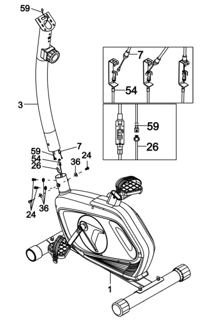
Meter Post Installation
- Remove x4 M815 Hexagon Bolts (24) and x4 08x020x1.5 Arc Washers (36) from the tube of Main Frame (1). Remove bolts using the S6 Allen Wrench provided.
- Connect the Sensor Wire (26) from the Main Frame (1) to the Extension Sensor Wire (59) from the Handlebar Post (3).
- Put the Cable end of the resistance cable of the Tension Control Knob (7) into the cable lock ofTension Cable (54). Pull the resistance cable tension Control Knob (7) up and force it into the slot of a metal bracket of the Tension Cable (54). Insert the metal fitting on the resistance cable of Tension Control Knob (7) into the hole at the end of the slot in the metal bracket of Tenison Cable (54).
- Connect the resistance cable of Tension Control Knob (7) to Tension Cable (54) complete.
- Insert the Handlebar Post (3) onto the tube of Main Frame (1) and secure with x4 M8x15 Hexagon Bolts (24) and x4 08x020x1.5 Arc Washers (36) that were removed.Tighten bolts using S6 Allen Wrench provided.
Tool:
|
Step 4: Handlebar Installation
- Remove x2 M8x15 Hexagon Bolts (24) and 2 08x016x1.5 Arc Washers (32) from the Handlebar Post (3).
- Attach the Handlebar (2) onto the Handlebar Post (3) with x2 M8x15 Hexagon Bolts (24) and x2 08x016x1.5 Arc Washers (32) that were removed. Tighten bolts using the Allen Wrench S6 provided.
Step 5: Display Installation
- Remove x2 M5x10 Cross Pan Head Screws (33) from the Display (10).
- Connect the Extension Sensor Wire (59) and Hand Pulse Sensor Wires (53) with the wires that come from the Display (10). Tuck wires into the hole of Handlebar Post (3), then attach the Display (10) onto the top end of Handlebar Post (3) with x2 M5x10 Cross Pan Head Screws (33) that were removed. Tighten screws using the Spanner with Phillips Screwdriver provided.
Tool:
|
|
Step 6: Seat Cushion, Seat Post-installation
- Remove x3 M6 Hexagon Bolts (42) and x3 co8xco16x1.5 Flat Washers (37) from the seat cushion (27).
- Attach the seat cushion (27) onto the Seat Slider (65) and secure using x3 M6 Hexagon Bolt (42) and x3 co8xco16x1.5 Flat Washers (37).
- Attach the Seat Slider (65) onto the Seat Post (25) using the M10 Knob (62) and 010x025x2.0 Flat Washer (61).
- Attach the Seat Post (25) onto Main Frame (1) using the M16 Seat Height Adjustment Knob (8).
Note:When adjusting the height of the seat post, ensure the seat post plastic bushing does not exceed the marked line on the seat post.
|

OPERATION
BUTTONSMode: Press this button to change over the display or choose the window that needs to be set.Set: In setting status, press this button to increase the setting value in the relevant flashing window for TIME, DIST, and CAL.Reset:
- In setting status, press this button to reset the value in the relevant flashing window for TIME, DIST and CAL, PULSE.
- In monitor status, hold this button for 3 seconds to reset all values to zero.
FUNCTIONAL AND OPERATIONSScan: Press the MODE button until “SCAN” appears, the Display will rotate through all 5 functions: Time, Speed, Distance, Calorie, and pulse. Each display will be held for 5 seconds.Time:
- Count the total time from exercise start to the end and the range is O – 99 minutes
- Exercise time can be set in advance, when it approaches the preset time, the monitor will alarm 4 seconds. The maximum pre-set time is 99 minutes.
Speed: Display instantaneous speed and the range is 0.0-9999km/h.
Distance:
- Count the total distance from the exercise start to the end and the range is 0.0 999.9km.
- Exercise distance can be set in advance, when it approaches the preset distance, the monitor will alarm 4 seconds. The maximum pre-set distance is 999.0km.Speed: Display instantaneous speed and the range is 0.0-999.9km/h.
Calories:
- Count the total calories consumed from exercise start to the end and the range is 0.0-999.9 KCAL.
- The calorie value can be set in advance, when it approaches the preset calorie, the monitor will alarm 4 seconds. The maximum pre-set calories are 999.0KCAL.
ODO: Display the total accumulated distance traveled.Pulse: By placing the palms of your hands on both of the contact pads the monitor will display your pulse rate in beats per minute during your workout.Note: The measurement value cannot be regarded as the basis of medical treatment.AUTO START/STOP
- Without any signal of exercise or operation for 4 minutes, the power will turn off automatically.
- Once receive exercise or operation signal, the display will turn on automatically
WARM UP & COOL DOWN ROUTINE
The warm-up is an important part of any workout. The purpose of warming up is to prepare your body for exercise and to minimize injuries. Warm-up for 2-5 minutes before commencing exercise.The purpose of cooling down is to return the body to its resting state at the end of each exercise session. A proper cool-down slowly lowers your heart rate and allows blood to return to the heart.To cool down at the end of your workout, repeat these exercises to reduce soreness in tired muscles.
|
Head RollsRotate your head to the right for one count; you should feel a stretching sensation up the left side of your neck. Then rotate your head back for one count, stretching your chin to the ceiling and letting your mouth open. Rotate your head to the left for one count and then drop yourhead to your chest for one count. |
|
Shoulder LiftsLift your right shoulder toward your ear for one count.Then lift your left shoulder up for one count as you lower your right shoulder. |
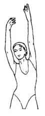 |
Side StretchesOpen your arms to the side and lift them until they are over your head. Reach your right arm as far toward the ceiling as you can for one count. Repeat this action with your left arm. |
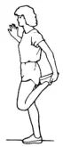 |
Quadriceps StretchWith one hand against a wall for balance, reach behind you and pull your right foot up. Bring your heel as close to your buttocks as possible. Hold for 15 counts and repeat with the left foot. |
 |
Inner Thigh StretchSit with the soles of your feet together and your knees pointing outward. Pull your feet as close to your groin as possible. Gently push your knees toward the floor. Hold for 15 counts. |
 |
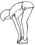
Toe TouchesSlowly bend forward from your waist, letting your back and shoulders relax as you stretch toward your toes.Reach as far as you can and hold for 15 counts. |
|
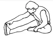
Hamstring StretchesExtend your right leg. Rest the sole of your left foot against your right inner thigh. Stretch toward your toe as far as possible. Hold for 15 counts. Relax and then repeat with the left leg. |
|
Calf/Achilles StretchLean against a wall with your left leg in front of the right and your arms forward. Keep your right leg straight and the left foot on the floor; then bend the left leg and lean forward by moving your hips toward the wall. Hold, then repeat on the other side for 15 counts. |
Need more information?We hope that this user guide has given you the assistance needed for a simple setup.For the most up-to-date guide for your product, as well as any additional assistance you may require, head online to help.kogan.com.
 report this ad
[xyz-ips snippet=”download-snippet”]